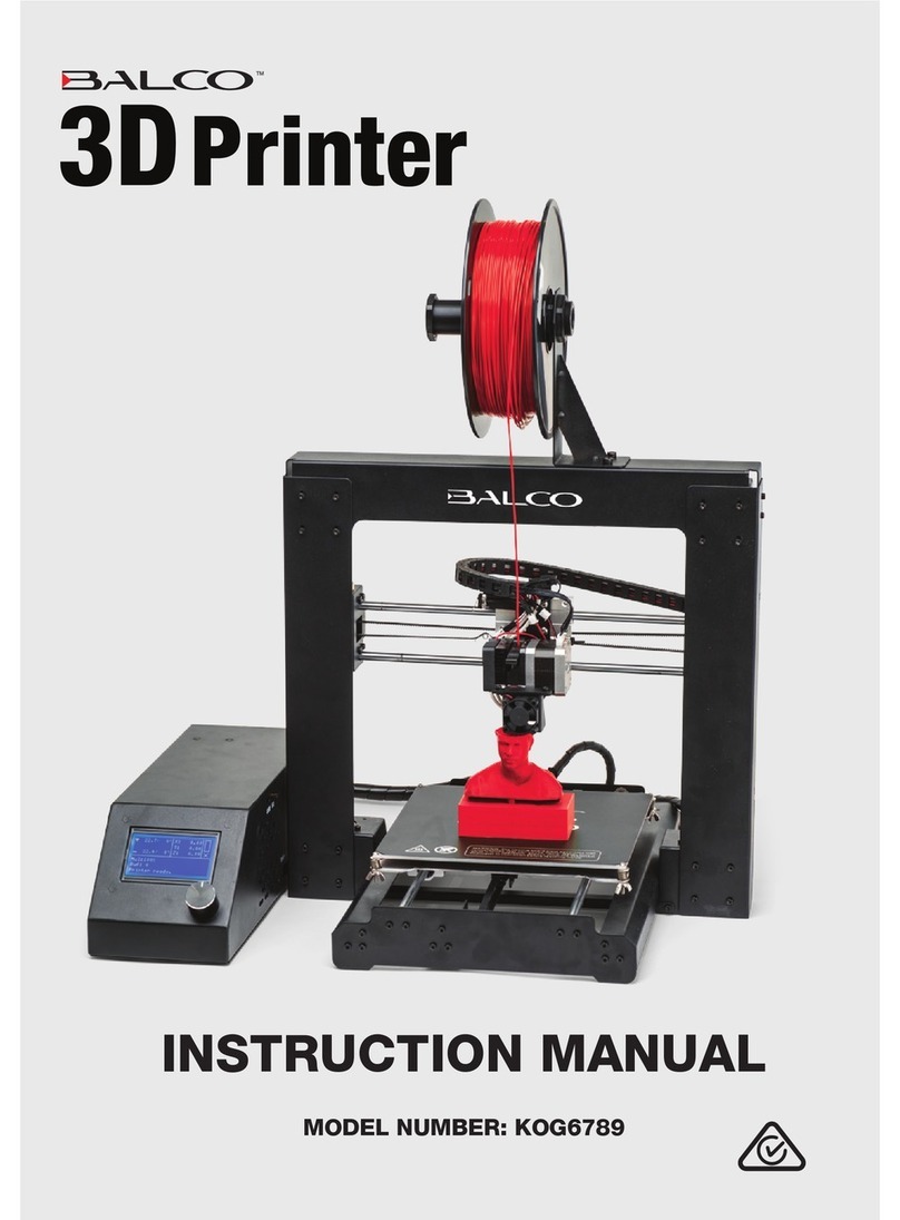
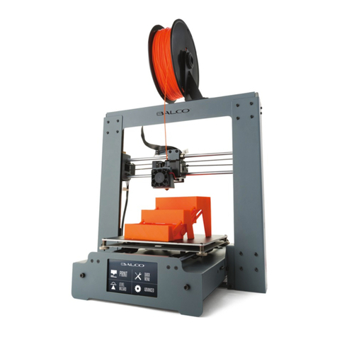
BALCO PrintMaker User manual

INSTRUCTION MANUAL
VERSION 1.0

2

3
Contents
Introduction 4
Safety 5
Glossary of Terms 6
Parts List 7
1.1 Accessories 7
Product Overview 8
2.1 Front & Back View 8
Technical Specications 9
Setup Instructions 10
3.1 Unboxing & Setup 10
3.2 Navigating the Menus 10
3.2.1 Build 10
3.2.2 Tools 11
3.3 Filament 12
3.3.1 Filament Types 12
3.3.2 Loading the Filament 13
3.3.3 Changing / Removing Filament 13
Additional Settings 14
4.1 Network 14
4.1.1 Wi-Fi 14
4.1.2 Ethernet Connection 14
4.1.3 Cloud Connection 14
4.2 Preheat Settings 15
4.3 Settings 15
4.4 About 16
Operation and Printing 17
5.1 Printing a File 17
5.1.1 Internal Memory 17
5.1.2 USB Stick 17
5.1.3 Wi-Fi Connection using Flash Print PC Software 17
5.1.4 Flash Cloud Print 19
5.1.5 Polar Cloud 20
5.2 During Printing 21
5.3 Removing 3D Objects from the Print Bed 21
5.4 Using the Camera 22

4
Introduction
Congratulations on the purchase of your new Balco PrintMaker 3D Printer!
3D Printing is a process whereby a real object is created from a 3D Design. Fused Filament
Fabrication (FFF) is one of the most common technologies used by 3D Printers to achieve this.
FFF works on an ‘additive’ principle by laying down material, such as PLA or ABS lament, in layers
to create a 3D object.
With hours of fun awaiting you, we’re sure you are excited to start printing, however, please read
this manual thoroughly before rst use and keep it in a safe place for future reference, along with
the warranty card and purchase receipt.

5
Safety
Before you get started, please read these important safety instructions
CAUTION: The Balco PrintMaker generates high temperatures and includes moving parts that can
cause injury. Never reach inside of the Balco PrintMaker while it is in operation, and allow time for the
printer to cool down after operation.
• Vapours/fumes may be irritating at operating temperatures. Always use the Balco PrintMaker
in an open, well ventilated area
• Do not leave the Balco PrintMaker unattended during operation
• Contact with extruded material may cause burns. Wait for printed objects to cool before
removing them from the build platform.
• Always take care when using the scraper. Never direct the scraper towards your ngers.
• Only use the PrintMaker in a clear working area
1. The printer must not be exposed to water or rain, or damage will occur.
2. The printer is designed to be used with ambient temperature ranging 15°C - 30°C (59°F -
86°F), and humidity ranging 20% - 50%. Operating outside these limits may result in low
quality models.
3. In case of emergency, turn o the PrintMaker at the power outlet.
4. The device must be placed in a dry and ventilated environment. The distances of the left, right
and back side space should be at least 20cm (7.8in), and the distance of the front side space
should be at least 35cm (13.7in). Device storage temperature: RT 0-40°C (32°F - 104°F)
5. It is recommended that you use eye protection when cleaning/sanding printed models to
avoid small particles contacting eyes.
6. Please read and understand the contents of this installation and user manual carefully. Failure
to read the manual may lead to personal injury, inferior results, or damage to the PrintMaker.
Always make sure that anyone who uses the 3D printer knows and understand the contents
of the manual and makes the most out of the PrintMaker.
7. PrintMaker is not intended for use by persons with reduced physical and/or mental
capabilities, or lack of experience and knowledge, unless they have been given supervision
or instruction concerning the use of the appliance by a person responsible for their safety.
Children should be under constant supervision when using the printer.
8. Before installation, you should make sure that the PrintMaker is unplugged from the power
supply. Only using furniture that can safely support PrintMaker.
9. The socket-outlet shall be installed near the equipment and shall be easily accessible

6
Glossary of Terms
Build Tape: The black tape that covers the PrintMaker’s print bed so that the object can stick to
the print bed well
Build Volume: The three dimensional amount of space that an object will use once it is
completed. The largest build volume is 150*150*150mm
Cooling Fan: Cools the outer assembly of the extruder and gear motor
Extruder: The integral extruder device installed on the X-Axis. The extruder draws the lament
from the spool, melts it and pushes it through the nozzle onto the print bed
Filament Compartment: Internal storage area located at the right of printer to store Balco
Filament
Filament Bowden Tube: A white plastic tube that guides the lament from the lament storage
compartment to the lament intake
Filament Intake: An opening located at the top of the extruder
Nozzle: Also called“print head”, located at the bottom of the extruder where heated lament is
pushed out
Print Bed: The surface on which the PrintMaker builds an object

7
Parts List
1. 3D printer
2. Filament
3. Unclogging pin tool
4. Allen wrench
5. Power cable
6. Screwdriver
7. Grease*
* Not pictured
21
5
3 4
6
1.1 Accessories

8
Product Overview
1. Bowden tube
2. Bowden quick coupler
3. Extruder base
4. Cooling Fan
5. Removable nozzle
6. Extruder cables
7. Clip
8. Led light
9. Turbo Fan Bae
10. Front door
11. Y-Axis sliding slot
12. Print base
13. Removable print bed
14. Touch-screen
15. USB stick input
16. Power switch
17. Power input
18. Spool holder
19. Filament cover
20. Filament cover handle
21. Motor
22. Filament intake
23. Filament feeding wheel
24. Top cover
25. Air outlet
26. Ethernet input
2.1 Front & Back View
24
26
25
16
7
8
9
12
13
14 15
16
17
18
19
20
21
22
23
2
3
4
5
10
11

9
Technical Specications
Name PrintMaker
Number of Extruder Single Removable Extruder
Print Technology Fused Filament Fabrication (FFF)
Screen Size 2.8” color IPS Touch Screen
Build Volume 150×150×150mm (5.9 x 5.9 x 5.9in)
Layer Resolution 0.1-0.4mm
Build Accuracy ±0.2mm
Positioning Accuracy Z axis 0.0025mm; XY axis 0.011mm
Filament Diameter 1.75mm (±0.07mm)
Nozzle Diameter 0.4mm
Build Speed 10~100 mm/s
Software FlashPrint
Support Formats Input: 3mf/stl/obj/fpp/bmp/png/jpg/jpeg File
Output: gx/g File
Memory Size 8G
OS Windows (XP and up), Mac OS, Linux
AC Input 150W (24V, 6.25A)
Connectivity USB stick, Wi-Fi, Ethernet
Device Size 388×340×405mm (15.27 x 13.38 x 15.94in)
Net Weight 9 kg (19.8lb)
Maximum radio-frequency
power transmitted: Less than 20dBm

10
Setup Instructions
3.1 Unboxing & Setup
1. Carefully remove your PrintMaker 3D Printer from the box, along with any additional
packaging around the printer
2. Plug the power cable into the side of the printer and press the power switch to ON to operate
the 3D Printer
3. To remove the protective cardboard inside the printer, go to Tools Settings Move on
the Touch Screen then long press the up arrow on the Z axis until the extruder is high enough
to remove the packaging
X
YZ
X:
20.00
Y:
45.00
Z:
36.00
<
2/3
<
Led
CameraMove
Filament Check
3.2 Navigating the Menus
This section provides a brief description of each menu function
and its associated sub-menu. Further details of each menu are
explained throughout the manual.
3.2.1 Build
Use the build menu to select and print les. Files can be loaded
to the PrintMaker 3D Printer via PC, USB, Wi-Fi or Cloud. Further
information on this menu under section 5.1 Printing a File on
page 17.
The following sections explain the settings available within the
Build menu, when loading les and during print.

11
Setup Instructions
File Interface
1. File details: Including picture of le, time needed,
lament needed
2. Build: Begin printing the le
3. Copy: Copy the les to the internal memory card from
the USB stick
4. Delete: Delete the print le
Print Screen Interface
1. Cancel: Cancel the print job
2. Pause/Resume: Suspend or resume the print job
3. More: Check additional settings during printing
Replace: Change lament during printing
Led Light: Turn ON/OFF the led light
Detail: Check additional printing details:
Extruder temperature
Print bed temperature
Used time
Printing progress
Filament needed
3.2.2 Tools
Network: Connect printer to the internet via Wi-Fi, cloud
or ethernet
Preheat: Preheat the extruder and print bed
Setting: Contains printer and operating functions
About: Information about the printer

12
3.3 Filament
This setting allows you to add, change and remove lament. The Balco PrintMaker uses high
quality PLA and ABS laments. We highly recommend using quality Balco laments as using
generic laments may cause damage to your PrintMaker 3D Printer or aect the print quality.
For beginners, we recommend using PLA materials as they are easy to print and do not produce
toxic fumes when printing. Before using other types of laments, ensure you understand the
advantages and disadvantages of other laments and their proper usage.
3.3.1 Filament Types
Filament Type PLA ABS PVA HIPS PETG
Extruder Temp 215ºC (419°F) 240ºC (464°F) 175ºC (347°F) 240ºC (464°F) 220ºC (428°F)
Heat Bed Temp 60ºC (140°F) 90ºC (194°F) 50ºC (122°F) 60ºC (140°F) 70ºC (158°F)
Ocial Name Polyactic Acid Acrylonitrile
Butadiene
Styrene
Polyvinylv
Alcohol
High Impact
Polystyrene
Polyethylene
Terephthalate
Printing Level Basic Advanced Advanced Advanced Intermediate
Advantages • Bioplastic
• Non-Toxic
• Less warping
issues
• Hard or
soft/ exible
variants
• High print
speed
• High
strength
• Scratch
resistant
• Smooth
nish
• Ideal for
mechanical
parts
• Water soluble
• Non-Toxic
• Lightweight
• Cost eective
• Dissolvable
in Limonene
• Good for
support
materials
• Very durable
• More exible
than PLA &
ABS
• Stronger
than most
laments
• Odorless
when
printing
Disadvantages • Low heat
resistance
• Easier to
break than
ABS
• Requires
thicker walls
than ABS
• Petro-
leum-based
• Non-biode-
gradable
• Heated print
bed required
• Fumes when
printing
• Sunlight de-
terioration
• Sensitive to
high heat.
• Risk of fumes
• Do not heat
over 190C
• Fumes when
printing
• Layer
separation
can occur
• Heated
chamber is
ideal
• Heated print
bed required
• Stickier
lament
when
printing
• Prone to
stringing
aect
• Can cause
drips if left in
hot extruder
when not
printing
• Heated print
bed required
Finishing • Sanding
possible
• Limited
gluing
• Easy sanding
• Easily soluble
in acetone
Gluing only Gluing only • Sanding
possible
• Limited
gluing
Setup Instructions

13
Setup Instructions
3.3.2 Loading the Filament
1. Open the lament cover located on the right-hand side of the printer. Insert the lament into
the lament intake (see the sticker arrow located on the printer for its location) and push the
lament into the feeding wheel until some resistance is felt
2. Once the lament is loaded, place the spool inside the lament cavity holder
Note:
• Ensure the lament has been pushed into the feeding wheel
• The loading direction of the lament wheel must be clockwise
3. On the touch screen, select Filament Load. The printer will heat the extruder to the
required temperature and will automatically feed the lament through the printer’s bowden
tube Please note this will take some time
4. Following the prompts on screen, tap OK once you see the lament extruding from the nozzle
5. Your lament is now loaded. Place the lament cover back onto the printer and close properly
6. Remove the extruded lament from the print bed area
3.3.3 Changing / Removing Filament
1. Remove the lament cover located on the right-hand side of the printer
2. On the touch screen select Filament Change, the extruder will start preheating
automatically. Once the desired temperature is reached, the printer will push the lament out
of the bowden tube and past the feeding wheel
3. Once the lament reaches the feeding wheel, remove the lament spool from the printer
4. To load a dierent lament type, following instructions under section 3.3.2 Loading the
Filament on page 13, otherwise place the lament cover back onto the printer

14
Additional Settings
The following section provides further information about the Tools main menu which includes
Network, Preheat Settings, General Settings and About sub-menus.
4.1 Network
4.1.1 Wi-Fi
1. Connect to wi- by selecting the ON/OFF button
2. Choose a network from the list and input the password
3. When connected, the wi- symbol will display on the top of the main menu
4.1.2 Ethernet Connection
1. Simply follow the prompts on screen by connecting the ethernet cable attached to your
modem into the back of the 3D printer
2. Once connected, a tick will appear on screen
4.1.3 Cloud Connection
To connect to either Polar Cloud or Flash Cloud, you must have a working internet connect via Wi-
Fi or ethernet. Secondly, you will need to register an account – to do this, visit one of the following
websites and follow the prompts to register an account:
• Polar Cloud – polar3D.com
• Flash Cloud – https://cloud.sz3dp.com/
Further instructions are provided under section Operation and Printing on page 17

15
Additional Settings
4.2 Preheat Settings
This menu allows you to adjust the temperature of the extruder and/or print bed. To do this:
1. Turn ON/OFF of the area you would like to preheat i.e. extruder and/or print bed
2. Using the plus / minus buttons, adjust the temperature accordingly and press the start button
once complete
3. A screen will appear showing the heating progress of each area
4. If you need to cancel the pre-heating, simply press the abort button
5. Hit the start button and your printer will commence changing the temperature of the
required area
Please note:
• Maximum extruder preheat temperature: 240°C (464°F)
• Maximum preheat temperature: 100°C (212°F)
4.3 Settings
1. Status: Displays the real-time coordinates of X-axis, Y-axis, Z-axis and the real-time
temperature of the extruder and platform
2. Language: Choose the required language
3. Calibration: Calibrate the initial distance between extruder and platform. After homing
completed, slide the piece of paper continuously back and forth between the nozzle and the
print bed. And simultaneously manually tap up and down arrow to adjust the distance until
the paper causes a slight friction. Tap [OK] to complete the calibration
4. Homing: Move the X, Y and Z axes back to the mechanical zero point
5. Move: Manually adjust the positions of extruder and print bed
6. Camera: Allows you to watch your print live. This setting can be turned ON/OFF
a. Auto Mode: During printing, camera will be on, USB o. When in idle/not printing,
camera will be o, USB on
b. Manual Mode: Users to manually choose when camera is turned on
Note: The USB and camera cannot be on at the same time
7. Filament Check: A notication which tells you when lament is used up or unable to
extrude. This notication can be turned on/o
8. Led: To turn on/o the light located inside the printer
9. Buzzer: Turns on/o buzzer which sounds when certain functions are made
10. Factory Reset: Deletes all internal memory and returns printer to original factory settings
11. Update: Update printer rmware

16
4.4 About
Shows the basic information about the printer
Additional Settings

17
5.1 Printing a File
Having a 3D design le is the rst step to creating a 3D object. The Balco PrintMaker accepts
multiple print les (see section Technical Specications on page 9). Print les can be
accessed by the PrintMaker via USB, Wi-Fi (via PC Software), Cloud connection and internal
memory. We highly recommend that you print your rst object using the les supplied in the
printer’s internal memory prior to attempting to use 3D designs from other sources.
5.1.1 Internal Memory
1. From the main menu select Build then select the rst icon at the top of the list which is
internal memory
2. From the list provided, select the le you would like to print. Details of the le including a
picture, print time and lament length required, will appear on screen
3. Select the print button icon as shown
4. The printer will commence heating the print bed as well as the nozzle extruder. This will take
some time before the printer will start to print the le
5. To pause or cancel a print simply follow the prompts on screen as outlined on section 3.2.1
Build on page 10 and 11
5.1.2 USB Stick
1. Insert a USB stick into the USB port located the front of the printer
2. From the main menu select Build then select the second icon at the top of the list which is
USB
3. From the list provided, select the le you would like to print. Details of the le including a
picture, print time and lament length required, will appear on screen
4. Select the print button icon as shown
5. The printer will commence heating the print bed as well as the nozzle extruder. This will take
some time before the printer will start to print the le
6. To pause or cancel a print simply follow the prompts on screen as outlined on section 3.2.1
Build on page 10 and 11
5.1.3 Wi-Fi Connection using Flash Print PC Software
1. Ensure you have a working internet connection – see section 4.1 Network on page 14
2. Download the FlashPrint PC software by visiting www.ashforge.com/download-center
then select Software Download and choose the option best suited to your computer
Operation and Printing

18
Operation and Printing
3. Once installed, open the program and add the PrintMaker printer by selecting the Print
menu Connect Machine
• Choose machine type FlashForge Adventurer 3
4. Change the connection mode to Wi-Fi and input your printers IP address (port). This can be
found by going to main menu on your printer, select Tools About, toggle to the second
page to nd IP-address. Enter this information into the Flash Print PC software and select
connect
5. Now that the printer is connected to the FlashPrint PC software, load your le by clicking on
the load button at the top of the screen or by going to File menu Load File
6. Once your le is loaded you can make adjustments to the size of the print, placement,
supports and various other settings. Once
you are happy with the le, select the print
button at the top of the screen
7. A window will appear requesting further
information. Adjust these settings
accordingly and press ok. Your le will then
be sliced to the correct le type
8. Once the le has been sliced correctly,
your printer will start to warm up and
prepare for printing. The PC software
screen will also change to show you the
progress of printing

19
5.1.4 Flash Cloud Print
1. Ensure you have a working internet connection and that you have registered a Flash Cloud
account as outlined on section 4.1 Network on page 14
2. Once registered, login to your account. Select My Printer Add Printer
3. Enter the printer’s name and register code. These details can be found on the printer Tools
Network Cloud Flash Cloud menu. After entering the details, also turn ON Flash Cloud
on your printer. Your printer should come up on screen and show as “idle”in the state column
4. To load a le, go to ‘My Model’ on the left hand panel, select Upload Model to select a le.
Once found, hit the upload button to return to the My Model screen, click on the uploaded
object and then click Print
5. Your le will appear on screen along with settings such as position and scale that can be
adjusted. Adjust accordingly and then select Print
6. A print screen will appear. Select start to commence warm up and printing. The Flash Cloud
screen will also change to show you the progress of printing
7. To turn on the camera during print, simply go to the My Printer screen, select your printer
and then click on the camera icon in the top right hand corner of the printer’s working area
(as illustrated below)
8. To pause or cancel a print, simply follow the prompts on screen or on your printer
Operation and Printing

20
Operation and Printing
5.1.5 Polar Cloud
1. Ensure you have a working internet connection and that you have registered a Polar Cloud
account as outlined on section 4.1 Network on page 14
2. To setup your printer login to the Polar Cloud website and click the icon on the top right
corner to go to Settings
3. Scroll to the bottom of the settings page to nd a‘PIN Code’which will be four digits
4. Connect your 3D printer to the Polar Cloud by going to the main menu and select Tools
Network Cloud Polar Cloud
5. Enter your account (email) and pin code details from the Polar Cloud settings menu as noted
in point 3, turn the Polar Cloud ON and hit save
6. After the connection is completed, you can see the printer’s information on the Polar Cloud
home page. Click on the printer
7. Click on Build Plate to load a le. Select your required le and upload to the print bed.
Adjust any placement and/or print settings then select print
8. Your print will appear in the bottom left corner of the screen and will start to slice your le.
Once sliced, a note saying “slicing completed” will appear on the print le
9. Finally select the start button on screen and your printer will commence printing
10. To pause or cancel a print, simply follow the prompts on screen or on your printer
Note:
• If you turn on the camera function, you can see the real time picture on the page
• When selecting a le, there are restrictions on le types that can be uploaded. These are noted
in the upload menu
Table of contents
Other BALCO 3D Printer manuals