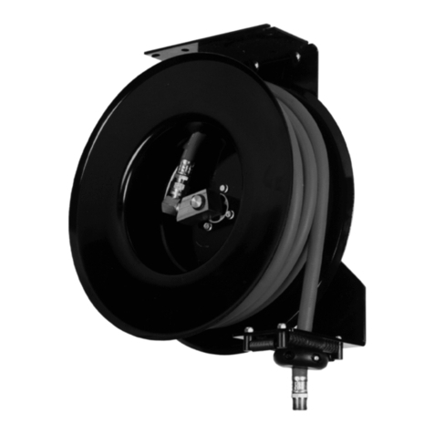
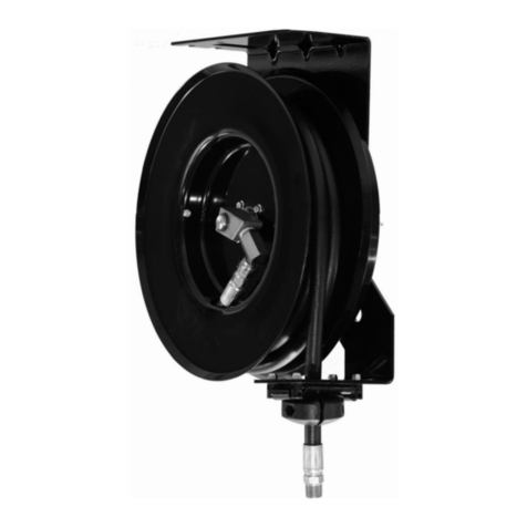
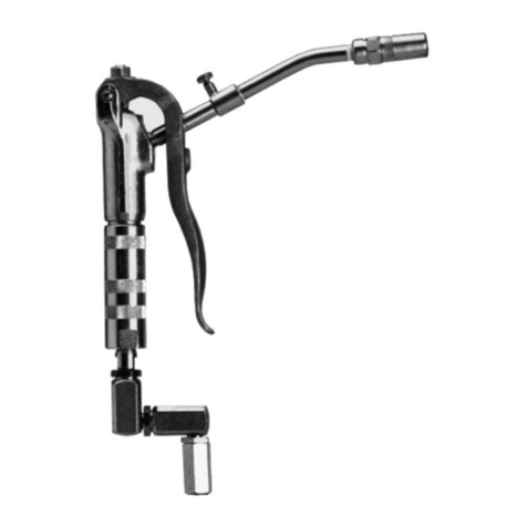
Balcrank Premium EV Series Instruction Manual

SERVICE BULLETIN SB2019
Rev A 04/09
Thoroughly read and understand this manual before
installing, operating or servicing this equipment.
OPERATION, INSTALLATION,
MAINTENANCE AND REPAIR GUIDE
Models: 2310-014
PREMIUM™DIESEL REELS
EV SERIES
EXTRA VOLUME TRANSFER
®
2310-015
2310-016
2310-017 (Bare Reel)
See pages 1 and 3 for
Technical Data.

2
General Safety
Thoroughly read and understand this manual before installing, operating or servicing this
equipment.
Because this Hose Reel can be
incorporated into a pressurized
systems, the following safety precautions should be
observed.
Check equipment regularly and repair or replace
worn and damaged parts.
Never alter or modify any parts of this hose reel,
doing so may cause damage to hose reel and/or
personal injury.
Under no circumstances should the dispensing
valve be aimed at any person at any time. Personal
injury may result.
Release pressures built up in the system before any
service or repair is begun. See the pressure relief
procedure below.
Do not operate bare air/water or lube reels above
3000 psi (206.9 bar). Do not operate bare grease
reel above 5000 psi (620.6 bar).
NOTE: If reel is equipped with hose, reel maximum
pressure will be determined by the lowest working
pressure rating of the hose, bare reel, or dispense
valve.
Always read and follow the uid manufacturer’s
recommendations regarding the use of protective
eyewear, clothing and respirators.
IMPORTANT
!
Pressure Relief Procedure:
Follow this procedure before maintaining and/
or repairing your Premium Hose Reel and/or
any part of system.
1) Disconnect the air to the pump.
2) Point dispensing valve away from
yourself and others.
3) Open dispensing valve until
pressure is relieved.
WARNING
!
The spring is ALWAYS under great tension and
could be propelled from the case with enough
force to cause serious bodily injury.
CAUTION
USE EXTREME CARE WHEN
HANDLING THE POWER SPRING!
!
Be sure the mounting
surface is strong enough to
support the reels, the
weight of the uids and the
stress caused by hard pulls on the service
hoses. See page 3 for dry weights of the hose
reel assemblies.
WARNING
!
WARNING
!
The MAXIMUM WORKING
PRESSURE of a hose reel is determined by the
lowest rated component in the assembly. The
hose reel Technical Data chart on page 3 give
the maximum working pressure of bare reels
and reels assembled at the factory with hose.
The maximum working pressure of a hose reel
is indicated on the hose reel identication plate
located near the base of the reel.
If adding a service hose and dispensing valve to
a bare reel, BE SURE you know the maximum
working pressure of ALL components!
WARNING
!
DANGER: Not for use with uids that
have a ash point below100°F (38°C).
Examples: gasoline, alcohol. Sparking
could result in an explosion which could
result in death.
CAUTION
!
Be aware of possible uid thermal expansion! A
pressure relief valve should be properly installed in
any system where this product is used. Should this
product fail as a result of thermal expansion and
no pressure relief valve was installed, the product
warranty will be voided.
FOR DIESEL FUEL ONLY. DO NOT exceed
50 psig (3.4 bar) pressure.
CAUTION
!

Table of Contents
General Safety Information............................ 2 Installation .................................................. 5-8
Model Numbers & Notes ............................... 3 Maintenance............................................. 9-12
Product Descriptions ..................................... 4 Troubleshooting Guide .................................12
Technical Data ............................................... 4 Parts Listings.......................................... 13-14
Dimensions and Mounting Diagram .............. 4 Notes ............................................................15
Warranty .......................................................16
Model Numbers
Type of Service Model
No.
Hose
Size
Maximum
Working
Pressure
Outlet
Hose
Inlet
Hose
Bare
Reel Wetted Parts
Diesel Fuel 2310-014 50’ x 3/4” 50 psi 8466-050 8466-002 2310-001 Steel (plated),
Buna-N, Bronze
2310-015 60’ x 3/4” 50 psi 8466-060 8466-002 2310-001
2310-016 50’ x 1” 50 psi 8481-050 8481-002 2310-001
Bare Reel
Model
No.
Bare Reel
W.P. (psi)
Thread Size Reel Dimensions Shipping Weight
Inlet Outlet L. W. H.
2310-017 3000 psi 1” 1” 19” 14” 24.5” 82 lbs.
Notes
3

Maximum Fluid Working Pressure:
Diesel Fuel Reels (Bare) ..............3000 psi
Material Inlet:
...................................................... 3/4” nptf
......................................................... 1” nptf
Material Outlet:
...................................................... 3/4” nptf
......................................................... 1” nptf
Wetted Parts:
Diesel Fuel.............Steel (plated), Buna-N,
........................................................Bronze
Hose Working Pressure Ratings:
................................................3/4” – 50 psi
1” – 50 psi
Shipping Weight Bare Reels:
Lrg. Frame ....................................... 82 lbs.
Figure 3
Hose Reel Dimensions
3/4” & 1” npt
Diesel Reel inlet
Product Description
The Heavy Duty Premium EV SeriesTM
diesel hose reel is designed for service
where longer capacities and larger volumes
of deliveries are required. The swivel is
balanced with equalized pressure on both
internal sides of the seals to eliminate
undue unbalanced friction. The roller outlet
is quickly adjustable to any of the three
mounting positions (i.e. wall, ceiling, or
table).
4

Fittings:
Item Qty Description
1 2 Male Connector 3/8 tubing x 3/8 npt
2 1 Pipe Nipple 3/8 npt x 6” long
3 2 Bushing 3/4 npt x 3/8 npt
4 2 Male Branch Tee 3/8 tubing x 1/4 npt
5 1 Union 3/8 tubing x 3/8 tubing
6 1 Male Elbow 3/8 tubing x 1/4 npt
7 4 90 Deg. Female Elbow 5/8 tubing x 1/2 npt
8 2 Union 5/8 tubing x 5/8 tubing
9 - 3/8 OD x .083 wall, soft copper tubing
10 - 5/8 OD x .083 wall, dead soft
Note: Due to random length of tubing additional
unions (8) may be required.
7A * Female Connector 5/8 tubing x 1/2 npt, two
required, replacing 2 units (7) for alternate
piping at pumps.
5

Note:
A pressure relief kit is recommended on
all Balcrank supply systems. The lack
of installing this kit will void all product
warranties if system fails because of
thermal expansion.
Installation
Table/Wall Mounting:
The hose reel has been shipped ready for use
when mounting to wall/table or mobile appli-
cations unless specied otherwise. If a Bare
reel has been ordered, see installation of hose
instructions and power spring adjustmen on
the following pages.
1. Select the mounting location. Be sure the
structure is secure and will not tip when reel is
in operation. Tables should be bolted to oor
and wall should be part of building structure.
2. Locate the mounting holes for drilling,
using measurements on previous page.
3. Fasten the base using bolts of a sufcient
strength to prevent the reel from “shearing
bolts” during operation when hose is pulled.
4. Connect supply line to the inlet of hose
reel. (see gure 5).
5. Install the hose stop and dispensing valve.
Position the hose stop so the hose extends far
enough for all operations.
Ceiling Mounting:
The hose reel has been shipped ready for use
when mounting to wall/table or mobile applica-
tions unless specied otherwise. The outlet
arm will need to be adjusted for ceiling mount-
ing. (see gure 8) The power spring tension
will ned to be adjusted for the ceiling height of
the building. If If a Bare reel has been ordered,
see installation of hose instructions and power
spring adjustmen on the following pages.
1. Select the mounting location. If the ceil-
ing is very high, suspend a suitable support
structure for the reels, so the soses will be long
enough to reach service area.
2. Locate the mounting holes for drilling, using
measurements on previous page.
3. Adjust the outlet arm position. Before
removing the roller ooutlet assembly and
the top tie bracket, the power spring tension
should be released and the uprights should
be secured to prevent accidental separation.
Once the outlet arm is positioned correctly
retighten bolts 80 to 90 inch pounds. (Refer
to illustrations on page 9 for further details on
changing the outlet arm position).
4. Fasten the base using bolts of a sufcient
strength to prevent the reel from “shearing
bolts” during operation when hose is pulled.
5. Connect supply line to the inlet of hose reel.
(see gure 5).
6. Install the hose stop and dispensing valve.
Position the hose stop so the hose extends far
enough for all operations.
Be sure the mounting surface is strong enough
to support the reels, the weight of the lubiricants,
and the stress caused by hard pulls on the ser-
vice hoses. See page 4 for dry weights of the
hose reel assemblies.
CAUTION
!
6

Installation
Installing a Service Hose on a Bare Reel:
WARNING
The MAXIMUM WORKING PRESSURE
of a hose reel is determined by the lowest
rated component in the assembly. The
maximum working pressure of a hose reel
is indicated on the hose reel identication
plate located near the base of the reel.
If adding a service hose and dispensing
valve to a bare reel, BE SURE you know
the maximum working pressure of ALL
components!
1. Locate or measure the length and size of
your hose in the charts below. Note:
how many times you must turn the spool
of the reel to properly adjust the spring
tension.
Low/Med. Press.
Hose Description
No. of Turns
3/4” I.D. X 50 F.T. 17
3/4” I.D. X 60 F.T. 18
1” I.D. X 50 F.T. 18
2. Place a piece of tape on the side of the
spool to help when counting the number
of turns made.
WARNING
Wear Heavy Leather Gloves when replac-
ing service hose and/or replacing power
spring to protect your hands from possibly
being cut.
3. Wearing Heavy Leather Gloves, rmly
grasp the outside edge of the spool with
both hands. Wind the reel to the proper
number of turns, rotating it in a clockwise
direction, stopping only at latching loca
tions. Stop the reel where the hose
swivel is accessible and where the stop
pawl is securely latched.
!
!
4. Before installing the hose, secure spool
from accidental rotation by placing a
clamp on the spool. See gure 7 for
proper placement of clamp. This will
keep the spool from rotating while install-
ing the hose.
WARNING
Never allow the reel to spin freely. Doing
so will cause the hose to spin out of con-
trol, which could cause serious bodily
injury if hit by the hose.
5. Uncoil the hose and attach bumper stop.
Attach the hose to the reel then remove
clamp carefully.
6. Firmly grasp the hose and pull it to release
the stop pawl. Slowly retract the hose. NOTE:
Check the power spring tension. The hose must
pull out fully and retract fully. To adjust, add or
remove ONE loop from the spool, extend the
hose and latch it. Do this as many times as
necessary until the power spring has the desired
tension.
7. Position the bumper stop so the hose
extends far enough for all operators to reach it.
CAUTION
Do Not put so many loops on to the reel
that the power spring winds tightly before
the hose is fully extended. A power spring
that has been wound too tight stops rotat-
ing before the hose is fully extended. This
condition will wear the hose and power
spring prematurely. To decrease tension,
remove one to two loops of hose from the
reel.
!
!
7

Installation
Increasing Power Spring Tension:
1. Pull the hose out fully and engage the
stop pawl.
2. Be sure the system pressure has been
relieved, follow the pressure relief pro
cedures below.
3. Remove the bumper stop and dispensing
valve.
4. Pull the hose back through the roller
outlet and wrap one loop of hose around
the spool.
5. Pull the hose back through the roller
outlet assembly and check the spring ten
sion; the hose must pull out fully and
retract fully. Continue to wrap more
loops, one at a time until the power
spring has the desired tension.
Adjusting the Outlet Arm Position:
Tank/Mobile Mounting Position:
1. Pull the hose out fully and engage the
stop pawl. Place C-clamp on spool to
prevent possible bodily injury
(see gure 8).
2. Remove screws (11) from the roller outlet
assembly and remove screws (11 & 12)
which hold the top tie bracket and outlet
arm assembly to the uprights. Reverse
the position of the roller outlet assembly
as shown in gure 10 and replace screws
(see gure 11).
Do Not put so many loops onto the reel that the
power spring winds tightly before the hose is fully
extended. A power spring that has been wound
too tight stops rotating before the hose is fully
extended. This condition will wear the hose and
power spring prematurely. To decrease tensioin,
remove one to two loops of hose from the reel.
CAUTION
!
Before removal of the roller outlet assembly and
the top tie bracket, the power spring tension
should be removed and the uprights should be
secured against accidental separation.
CAUTION
!
Pressure Relief Procedure:
Follow this procedure before maintaining and/
or repairing your Premium Hose Reel and/or any
part of the system.
1) Disconnect the air to the pump.
2) Point dispensing valve away from yourself and
others
3) Open dispensing valve until pressure is
relieved.
WARNING
!
8

Maintenance
Replacing Service Hose:
1. Be sure the pressure supply has been
relieved when replacing the service hose.
Follow the pressure relief procedures
below.
2. Fully extend the service hose, stop the
reel where the hose swivel union is
accessible and where the stop pawl is
securely latched.
3. Secure spool from accidental rotation
by placing a C-clamp onto the spool.
See gure 12 for proper placement of
C-clamp. This will keep the spool from
rotating while installing the new service
hose.
4. Disconnect and remove service hose.
5. Uncoil the new hose and assemble the
bumper stop, attach the new hose to the
reel. and remove the C-clamp carefully.
6. Firmly grasp the hose and pull it, to
release the stop pawl. Then Slowly
retract the hose.
NOTE: Check the power spring tension.
The hose must pull out and retract fully.
Wrap ONE more loop onto or off the spool,
extend the hose, and latch it. Do this as
many times as necessary until power spring
has the desired tension.
Never allow the reel to spin freely. Doing so
will cause the hose to spin out of control, which
could cause serious injury if hit by the hose.
WARNING
!
Replacing the Swivel:
1. Be sure the pressure supply has been
relieved when replacing the swivel.
Follow the pressure relief procedures
below.
2. Disconnect the inlet hose.
3. Remove the old swivel assembly and
replace it iwth the new assembly. NOTE:
the new assembly may look different from
the old assembly, the important item to be
sure of is thread size and pressure style (ex:
L.P., M.P. or H.P.) used on your reel.
(Refer to parts listing on page 1 for proper
swivel repair or replacement kit.)
NOTE: A spring wound too tightly stops
rotating before the hose is fully extended.
This condition will place excessive strain
on the hose and power spring that could
damage and/or shorten the life of the reel.
Pressure Relief Procedure:
Follow this procedure before maintaining and/or repairing
your Premium Hose Reel and/or any part of the system.
1) Disconnect the air to the pump.
2) Point dispensing valve away from yourself and others
3) Open dispensing valve until pressure is relieved.
WARNING
!
9

Pressure Relief Procedure:
Follow this procedure before maintaining and/
or repairing your Premium Hose Reel and/or any
part of the system.
1) Disconnect the air to the pump.
2) Point dispensing valve away from yourself and
others
3) Open dispensing valve until pressure is
relieved.
WARNING
!
USE EXTREME CAUTION WHEN HANDLING
THE POWER SPRING! The spring is ALWAYS
under great tension and could be propelled from
the case with enough force to cause serious
bodily injury. To reduce the risk of serious bodily
injury, use extreme caution when removing the
top cover (20). Be sure the spring case is lying
at, and then carefully lift up the cover to expose
the power spring.
WARNING
!
Maintenance
Replacing Power Spring:
1. Be sure the pressure supply has been
relieved. Follow the pressure relief
procedures below.
2. Disconnect inlet hose. Remove the reel
to work bench and clamp reel base
securely.
3. Remove hose stop and control dispens
ing valve, retract the hose and remove
nesessary wraps until all power spring
tension has been removed.
4. Remove screws (11, 12 & 16) from base
(40), hub (29) and top tie bar (19).
5. Unclamp the reel form the workbench
and lay it on a at work surface so the
spring case (21) is facing up.
6. Twist the complete spring case assembly
to the left or right and once the upright
(15) is clear of the base (40) and the top
tie bar (19) lift to remove the assembly.
NOTE: Be sure that both bolts (24) and
safety cotter pins (20) are still in place on
each side of the case before lifting. (see
gure 12 for placement of cotter pins).
7. Be sure case is lying at on the work
surface, now remove bolts (24). Next
using extreme caution, remove both
safety cotter pins from sides of case
and lift up on the spring case cover (22)
to expose the power spring.
8. Carefully inspect the Power Spring; If
either end of the power spring is worn
or damaged and will not engage the
center plates (26) properly, replace the
power spring. If the power spring has
become uncoiled inside the spring case,
the “keeper” has failed. It is strongly
advised that you replace the complete
spring case assembly. The “keeper”
is a metal band that is placed around the
power spring to keep it from uncoiling
when removed from the case. If you
attempt to remove the power spring
when this condition has occurred the
spring will uncoil quickly and can cause
serious bodily injury. (see gure 10)
9. Apply a light coat of grease inside the
spring case and cover.
10. Install the new power spring, making
sure that it is laid into the spring case
counter clockwise and that the outside
end loop is around spring case bolt (24)
and spacer (10).
11. Replace spring case cover (23) and
insert cotter pins (20) through sides of
spring case and cover. Tighten case
and cover to upright (15).
(continued on next page)
10

47
Replacing Power Spring “continued”:
12. Twist the complete spring case assem
bly to the left or right, making sure
that the power spring is centered and
has engaged the spring center plates
(26).
13. Align upright assembly (15) with base
(40) and top tie bar (19). Place bolts
(11 & 12) back through the base and
top tie bar and tighten to 100 - 110 inch
pounds. Inspect complete reel for
proper function and adjust power spring
as needed by adding one to two loops
of hose at a time to increase power
spring tension.
11

Maintenance
Stop Pawl Replacement:
1. Allow the hose to retract as far as the
hose stop to remove tension from the
power spring and to be sure that the stop
pawl is not engaged with the ratchet.
2. With the stop pawl assembly free to be
moved by hand, remove the cotter pin
(38), spring (37) and snap ring (39).
Once this has been done the complete
assembly can be removed.
3. Item (36) bronze bearing will need to be
knocked out of the upright (41), using a
punch and hammer.
4. With the stop pawl kit in hand replace
the bronze bearing by pressing the new
bearing into the upright (41).
5. Apply a light coat of grease to the stop
pawl stud (35), reassemble by placing
the stop pawl stud (35) back through the
bronze bearing (36) and insert the snap
ring (39) into the groove on the shaft of
the stop pawl stud (35).
6. Replace the spring (37) and cotter pin
(38) with the new ones provided in the
kit.
7. Check the stop pawl assembly by hand
for free movement. The stop pawl
assembly should not stick or drag and it
should return to its central position each
time it is moved off center.
NOTE: Number with “*” is a component of the
stop pawl repair kit # 811128.
Figure 8
Stop Pawl Replacement
NOTE: If the assembly does not appear to
be returning back to its neutral position, the
spring tension may need to increased. You
can increase the spring tension by bending
the cotter pin closer to the stop pawl shaft
which will stretch the spring slightly.
Troubleshooting Guide
Trouble Probable Cause Remedy
No spring tension Power spring broken (item 22) Replace power spring (see pg 10)
Low or high tension on hose Lost wraps or too many wraps of
hose on reel
Add of take off wraps of hose by pull-
ing hose on reel down just enough
to allow stop pawl to engage ratchet.
Now wraps can be added or taken off
as needed. (see pg 8)
Hose will not retract Stop pawl lock-up CAUTION: Wearing heavy leather
gloves, rmly grasp the outside edge
of the spool with both hands. Release
the tension on the stop pawl by hand
for one or two revolutions.
Stop pawl will not engage Spring broken or unhooked Replace or repair (item 39)
Swivel leaking Worn o-rings or block Replace swivel (item 35)
Never alter or modify any parts of this reel.
Doing so may cause damage to reel and/or
personal injury. Always use genuine Balcrank
replacement parts.
CAUTION
!
12

35
35
48
48
88
51
13

NOTE: (*) Component of
“Roller Outlet
Assembly #X820025
(**) Component of
“Stop Pawl Assembly
#811128
Parts Listing for Premium
EV Diesel Reels
2310-017
2310-014
2310-015
2310-016
ITEM PART # DESCRIPTION QTY
1805818 10-24 x 1/2” Rd. Hd Screw 4 x x x x
2807171 Outlet Frame (*) 2 x x x x
3807172 Outlet Roller (*) 6 x x x x
4807173 Outlet Pin (*) 6 x x x x
5820165 (1) Slider Frame (*) 1 x x x x
6814247 10-24 Hex Nut (*) 4 x x x x
7820003 Slide Rod (*) 2 x x x x
8 820166 (1) End Support (*) 2 x x x x
9819066 1/4-20 x 1/2” Hx. Hd Bolt (*) 8 x x x x
10 831730 Spacer (after 1/04) see pg. 11 1 x x x x
11 805823 1/4-20 x 3/4” Hx. Hd Bolt 26 x x x x
12 805784 1/4” Lock Washer 6 x x x x
13 808984 (1) Roller Outlet Brace 2 x x x x
14 813561 1/4-20 Elastic (Nylok) Nut 22 x x x x
15 X810638 (1) Right Hand Upright Assy 1 x x x x
16 805795 3/8-16 x 1/2” Hx. Hd Bolt 1 x x x x
17 813738 3/8” Star Lock Washer 1 x x x x
18 806186 3/8” Flat Washer 1 x x x x
19 809267 (1) Top Tie Bar 1 x x x x
20 808719 3/32 x 1-1/4” Cotter Pin 2 x x x x
21 824459 Spring Case 1 x x x x
22 813014 Power Spring 1 x x x x
23 832319 Spring Case Cover 1 x x x x
24 825720 1/4-20 Rd. Hd Screw 2 x x x x
25 808764 7/32 x 1-5/8” Roll Pin 2 x x x x
26 813779 Spring Center Plate 2 x x x x
Parts Listing for Premium
EV Diesel Reels
2310-xxx
2310-014
2310-015
2310-016
ITEM PART # DESCRIPTION QTY
27 808967 Spacer-Spring Center Plate 1 x x x x
28 809311 Support Plate 1 x x x x
29 808793 (1) Hose Reel Disc 2 x x x x
30 809266 Disc & Ratchet Spacer 11 x x x x
31 829236 Low/Med Pressure Hub 1 x x x x
32 829240 Ratchet 1 x x x x
33 826829 Outlet Adapter 1 x x x x
34 809258 60 Deg. Elbow 1 x x x x
35 829258 Low/Med Pressure Swivel 1 x x x x
36 X810639 Left Upright Assy (1) 1 x x x x
37 809860 Stop Pawl & Stud (**) 1 x x x x
38 826395 Stop Pawl Bearing (**) 1 x x x x
39 807727 Stop Pawl Spring (**) 1 x x x x
40 805743 3/32 x 3/4” Cotter Pin (**) 1 x x x x
41 826396 Snap Ring (**) 1 x x x x
42 808315 10-24 x 1” Rd. Hd Screw 1 x x x x
43 809269 Base Plate (1) 1 x x x x
44 N/A Spool Assembly 1 x x x x
45 820499 1/4-20 x 1” Bolt 4 x x x x
46 805835 10-24 Hexnut 2 x x x x
47 831729 Spacer w/Shoulder (after 1/04 see pg. 11) 1 x x x x
48 824480 1/4-20 x 1/2 whiz lock screw 16 x x x x
49 826398 Hose Stop 3/4” (not shown) 1 x x
826399 Hose Stop 1” (not shown) 1 x
50 820230 Bushing, 1” to 3/4” (not shown) 1 x x
51 831489 Ring, Terminal grounding (green) x x x
(1) When ordering these components please
specify green paint for Diesel reels.
CAUTION
Never alter or modify
any parts of this reel.
Doing so may cause
damage to reel and/or
personal injury. Always
use geniune Balcrank®
replacement parts.
!
PARTS LISTING
PREMIUM EV DIESEL REELS
14

NOTES
15

Balcrank®Corporation
Weaverville, NC 28787
800-747-5300
800-763-0840 Fax
www.balcrank.com
SERVICE BULLETIN SB2019
Rev A 04/09
832419
16
Balcrank Lubrication Equipment Warranty Statement
All Balcrank equipment sold by authorized Balcrank distributors is warranted to their original customer to be free from defects in materials and workmanship
for a period of one year from the date of sale to that customer. Selected Balcrank equipment carries warranty terms for a more extended period as dened in
the Balcrank Lubrication Equipment & Accessories User Price List, wherein a “lifetime” warranty represents a warranty period of thirty years. Within the initial
one-year warranty period, Balcrank will repair or replace all Balcrank equipment determined by Balcrank to have defective materials or workmanship. For
equipment carrying more extended warranties, Balcrank will repair or replace the product including parts and labor during the rst full year and will provide
parts only for the remainder of the warranty period.
This warranty applies only to equipment installed and operated according to applicable Balcrank Service Bulletins and Installation Instructions.
Any equipment claimed to be defective must be returned, freight prepaid, to an Authorized Balcrank Service Center (ASC). Upon receiving candidate warranty
equipment from a customer, ASC will: 1) diagnose to determine the warrantable condition of the equipment, 2) submit, prior to repair or replacement, a
request to Balcrank for warranty authorization, then 3) in cooperation with Balcrank, proceed with repair locally or forward the equipment to Balcrank and
obtain replacement. If the part(s) or equipment items are found defective upon inspection by Balcrank, they will be repaired or replaced, and then will be
returned to the ASC. If Balcrank nds the claimed part(s) or equipment not to be defective, the ASC will receive written authorization from the original
customer, and then repair them for a reasonable charge to the customer, which will include all applicable parts, labor, and return transportation costs.
Optionally, the customer may submit certain eligible products directly to Balcrank for warranty return by using Balcrank Lubrication Equipment Direct Service
Warranty Procedure. Eligible products are dened in the Balcrank Lubrication Equipment & Accessories User Price List. Refer to the Balcrank web site www.
balcrank.com for a copy.
Any equipment returned to Balcrank must have the Warranty Service Claim number (WSC#) clearly marked on the outside of the carton. Balcrank’s sole
responsibility is for defects in material and workmanship, and Buyer’s sole and exclusive remedy hereunder, shall be limited to repair or replacement of the
defective part or equipment.
This warranty does not cover, nor shall Balcrank be liable for repair or replacement of parts or equipment resulting from general wear and tear through use,
or damage or failure caused by improper installation, abuse, misapplication, abrasion, corrosion, insufcient or improper maintenance, negligence, accident,
alteration, or substitution of non-Balcrank parts.
Furthermore, the Warranty for Lubrication Equipment and Accessories does not cover the following specic conditions:
• Failure or damage to equipment caused by dirt or debris in compressed air lines and uid lines. This includes, but is not limited to, clogged inlet lters,
strainers, or regulators; uid meters; control handles; uid tips; and valves.
• Failure of normal wear parts including but not limited to: o-rings, packings, seals and valves unless originally improperly installed by the factory.
• Products placed in applications for which their use was not intended. Examples include but are not limited to Lubricant pump being used
to pump solvents, or placing equipment intended strictly for indoor use outdoors
• Damage to equipment resulting from operation above and beyond Balcrank’s recommendations.
• Leaks at air and uid ttings and connections.
• Damage caused by thermal expansion whenever adequate pressure relief was not included in the system.
• Loose suction tubes on pumps.
• Incorrect hose reel spring tension, requiring adjustment.
THERE ARE NO OTHER WARRANTIES, EXPRESSED OR IMPLIED, INCLUDING WARRANTIES OF MERCHANTABILITY OR FITNESS FOR A
PARTICULAR PURPOSE. IN NO EVENT SHALL BALCRANK BE LIABLE FOR ANY SPECIAL, CONSEQUENTIAL, OR OTHER DAMAGES OF SIMILAR
NATURE, INCLUDING BUT NOT LIMITED TO LOST PROFITS, LOST PRODUCTION, PROPERTY DAMAGE, PERSONAL INJURY, WHETHER SUFFERED
BY BUYER OR ANY THIRD PARTY, IRRESPECTIVE OF WHETHER CLAIMS OR ACTIONS, LEGAL OR EQUITABLE, FOR SUCH DAMAGES ARE BASED
UPON CONTRACTS, WARRANTY, NEGLIGENCE, STRICT LIABILITY, OR OTHERWISE. ANY CLAIM OR ACTION FOR BREACH OF WARRANTY MUST
BE BROUGHT WITHIN TWO (2) YEARS FROM THE DATE OF SALE TO THE ORIGINAL CUSTOMER.
Revision Log:
New Release 11/07
Rev A - 04/09 Updated warranty statement
Other manuals for Premium EV Series
1
This manual suits for next models
4
Table of contents
Other Balcrank Tools manuals

Balcrank
Balcrank Premium Series Reference manual

Balcrank
Balcrank Premium EV Series Instruction Manual

Balcrank
Balcrank Premium Series Instruction Manual

Balcrank
Balcrank 2510-010 Instruction Manual

Balcrank
Balcrank Signature DEF Series Instruction Manual

Balcrank
Balcrank Signature Series Instruction Manual

Balcrank
Balcrank PREMIUM 2110 Series Instruction Manual

Balcrank
Balcrank 3310-030 Instruction Manual