General Safety
Thoroughly read and understand this
manual before installing, operating or
servicing this equipment.
Because this Hose Reel can be
incorporated into a pressurized
systems, the following safety
precautions should be observed.
Check equipment regularly and repair or
replace worn and damaged parts.
Never alter or modify any parts of this hose
reel, doing so may cause damage to hose reel
and/or personal injury.
Under no circumstances should the dispensing
valve be aimed at any person at any time.
Personal injury may result.
Release pressures built up in the system
before any service or repair is begun. See the
pressure relief procedure below.
Do not operate bare air/water or lube reels
above 3000 psi (206.9 bar). Do not operate
bare grease reel above 5000 psi (620.6 bar).
NOTE: If reel is equipped with hose, reel
maximum pressure will be determined by the
lowest working pressure rating of the hose,
bare reel, or dispense valve.
Always read and follow the uid manufacturer’s
recommendations regarding the use of
protective eyewear, clothing and respirators.
IMPORTANT
!
Pressure Relief Procedure:
Follow this procedure before maintaining
and/or repairing your Premium Hose Reel
and/or any part of system.
1) Disconnect the air to the pump.
2) Point dispensing valve away from
yourself and others.
3) Open dispensing valve until
pressure is relieved.
WARNING
!
The spring is ALWAYS under great tension and
could be propelled from the case with enough
force to cause serious bodily injury.
CAUTION
USE EXTREME CARE WHEN
HANDLING THE POWER SPRING!
!
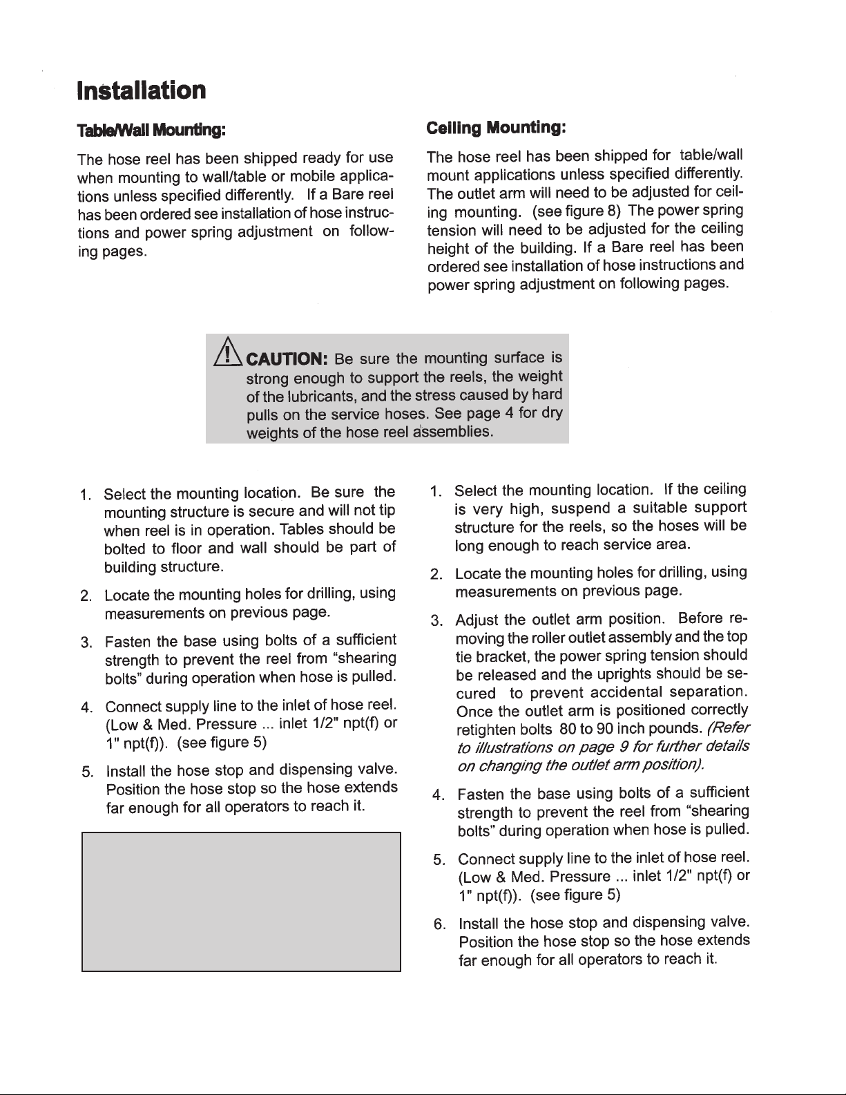
Be sure the mounting surface
is strong enough to support
the reels, the weight of the
uids and the stress caused
by hard pulls on the service hoses. See
page 3 for dry weights of the hose reel
assemblies.
WARNING
!
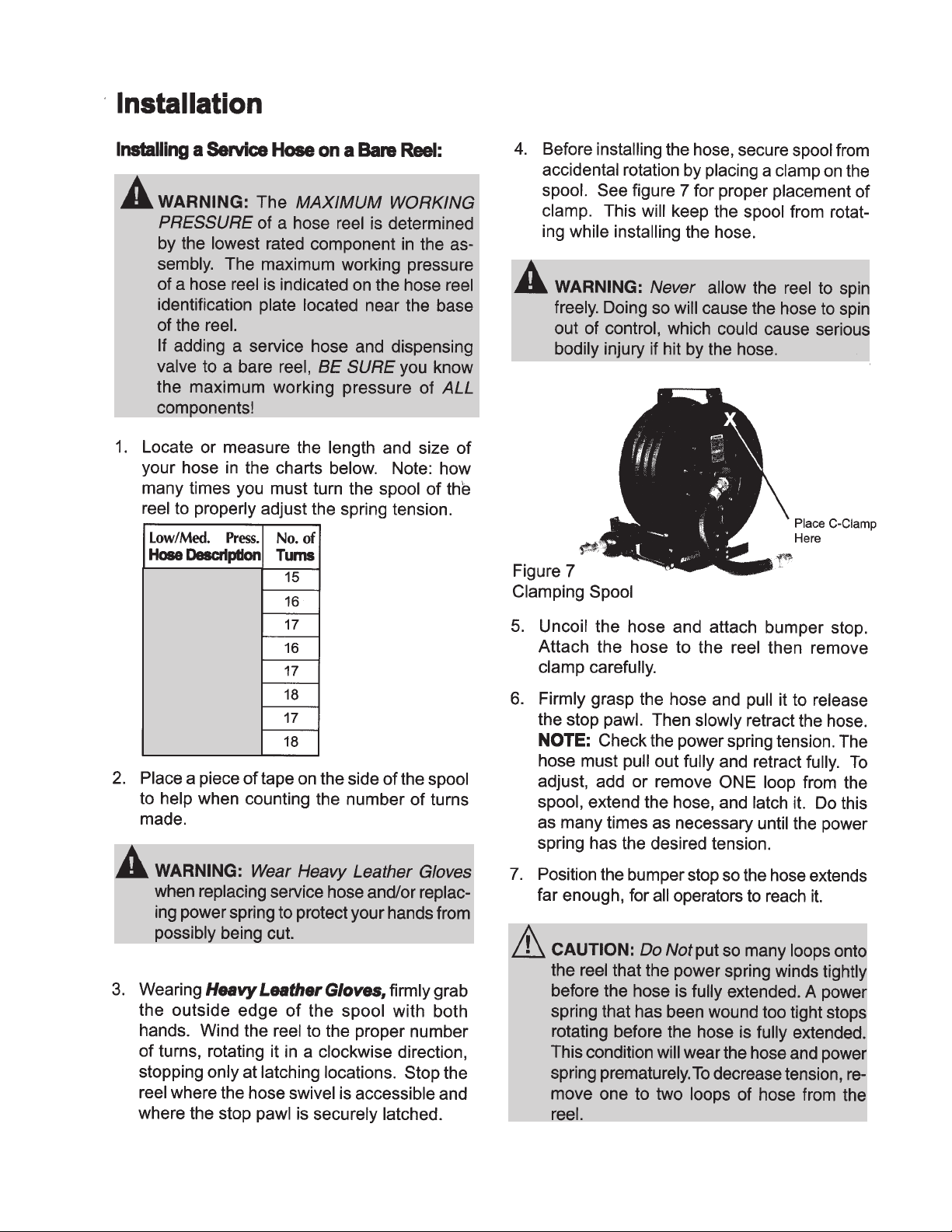
WARNING
!
The MAXIMUM WORKING
PRESSURE of a hose reel is
determined by the lowest rated component
in the assembly. The hose reel Technical
Data chart on page 3 give the maximum
working pressure of bare reels and reels
assembled at the factory with hose. The
maximum working pressure of a hose reel
is indicated on the hose reel identication
plate located near the base of the reel.
If adding a service hose and dispensing
valve to a bare reel, BE SURE you know
the maximum working pressure of ALL
components!
WARNING
!
DANGER: Not for use with
uids that have a ash point
below 100°F (38°C). Examples:
gasoline, alcohol. Sparking could
result in an explosion which could result in
death.