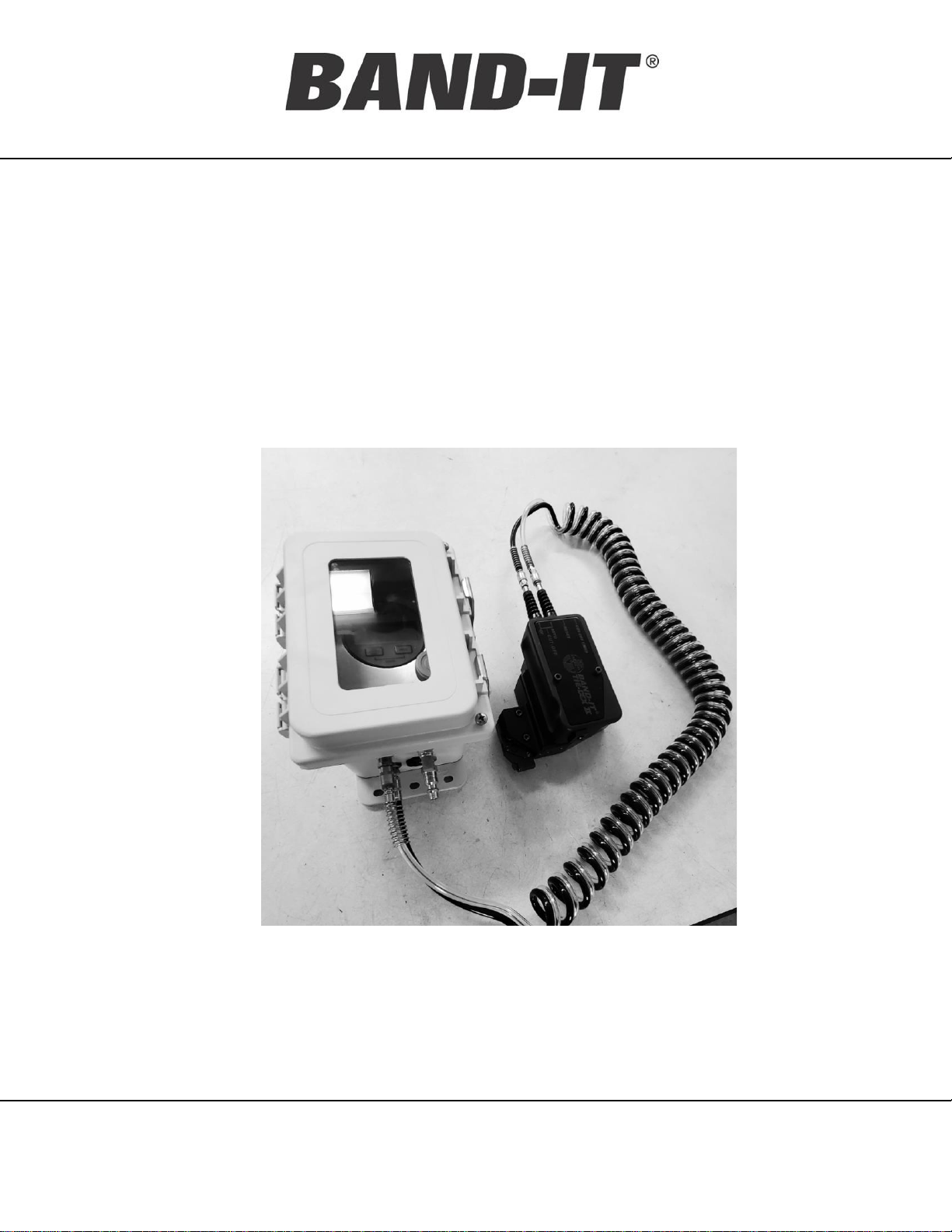
Band-it A35199 User manual

A351, A355
PNEUMATIC TOOL
www.BAND-IT-IDEX.com Document # P35087 Rev. I
© Copyright
BAND-IT-IDEX, Inc. 2021
All rights reserved
Page 1 of 19
BAND-IT-IDEX, Inc.
A Unit of IDEX Corporation
4799 Dahlia Street
Denver, CO 80216-3070 USA
P: 1-800-525-0758
F: 1-800-624-3925
Operating
Manual
A35199, A35599
Pneumatic tool
Operation Instructions
Original document
(not a translation) U.S. Patent No.
11034472

A351, A355
PNEUMATIC TOOL
www.BAND-IT-IDEX.com Document # P35087 Rev. I
© Copyright
BAND-IT-IDEX, Inc. 2021
All rights reserved
Page 2 of 19
BAND-IT-IDEX, Inc.
A Unit of IDEX Corporation
4799 Dahlia Street
Denver, CO 80216-3070 USA
P: 1-800-525-0758
F: 1-800-624-3925
Operating
Manual
Page Description Page #
Safety Guidelines 3
Overview (Air Regulator & Tool Body) 4-6
Air Requirement 7
Initial Tool Set-up 8
Operation Instruction & Band Inspection 9-11
Maintenance 12-14
Replacement Parts 15
Tool Calibration Instructions 16-17
Foot Control/Bench Mount (Optional) 18
Tool Balancer Installation 19
Table of Contents

A351, A355
PNEUMATIC TOOL
www.BAND-IT-IDEX.com Document # P35087 Rev. I
© Copyright
BAND-IT-IDEX, Inc. 2021
All rights reserved
Page 3 of 19
BAND-IT-IDEX, Inc.
A Unit of IDEX Corporation
4799 Dahlia Street
Denver, CO 80216-3070 USA
P: 1-800-525-0758
F: 1-800-624-3925
Operating
Manual
DANGER—Misuse of this tool may result in injury to personnel.
•Only use the equipment for its intended purpose, as described in this manual
▪Please read this entire manual before unpacking, setting up or operating this device.
Pay attention to all danger and caution statements. Failure to do so could result in serious injury
to the operator or other personnel, or damage to the equipment.
CAUTION
▪Protective eyewear should be worn when connecting and disconnecting the tool to compressed
air sources and during operation.
▪Wear appropriate gloves for handling steel while operating this tool, applying stainless steel
clamps and removing scrap clamp tail.
▪Clamp tensioning can be immediately stopped by releasing the tool trigger system.
▪When applying clamps, care should be taken to ensure fingers and loose clothing are not in the
way of the clamp being applied.
▪Never attempt to clamp objects which have a potential to burst, shatter or otherwise cause
bodily harm.
▪Disconnect air supply prior to maintenance and disassembly of tool components.
▪Liquids or lubricants should never be put into the air lines.
▪Risk of pinch point:
Located at tool head and interface during tension cycle
It is the task of the employer to warn his or her staff of risks, to train them on prevention of
accidents, and to provide necessary safety equipment and devices for the operator’s safety.
Before starting to work with the device, the operator should check the features of the device
and learn all details of the device’s operation. The device should only be operated by staff
members who have read and understand the contents of this manual.
Safety Guidelines

A351, A355
PNEUMATIC TOOL
www.BAND-IT-IDEX.com Document # P35087 Rev. I
© Copyright
BAND-IT-IDEX, Inc. 2021
All rights reserved
Page 4 of 19
BAND-IT-IDEX, Inc.
A Unit of IDEX Corporation
4799 Dahlia Street
Denver, CO 80216-3070 USA
P: 1-800-525-0758
F: 1-800-624-3925
Operating
Manual
Precision Regulator
Inside Under Clear
Cover
Overview: Air Regulator
Air Supply Inlet
Mounting Bracket
Air Pressure
Regulator
Factory set
Do not adjust
Digital Pressure Gage
Inside Under Clear
Cover
Fig. 1a
Air Filter
Fig. 1b
Quick Connector
For Flexible Cord
to Tool

A351, A355
PNEUMATIC TOOL
www.BAND-IT-IDEX.com Document # P35087 Rev. I
© Copyright
BAND-IT-IDEX, Inc. 2021
All rights reserved
Page 5 of 19
BAND-IT-IDEX, Inc.
A Unit of IDEX Corporation
4799 Dahlia Street
Denver, CO 80216-3070 USA
P: 1-800-525-0758
F: 1-800-624-3925
Operating
Manual
Overview: Bench Top Mounting Hole Pattern
(for Air Regulator Box backet)
Air Regulator Box Mounting
In a permanent installation, air regulator box should be bolted to a flat surface
to allow flexible cord to be stretched without dragging air regulator box.
Keep filter vertical to maximize the water and contaminant capability.
Fig. 2

A351, A355
PNEUMATIC TOOL
www.BAND-IT-IDEX.com Document # P35087 Rev. I
© Copyright
BAND-IT-IDEX, Inc. 2021
All rights reserved
Page 6 of 19
BAND-IT-IDEX, Inc.
A Unit of IDEX Corporation
4799 Dahlia Street
Denver, CO 80216-3070 USA
P: 1-800-525-0758
F: 1-800-624-3925
Operating
Manual
Important: Before disassembling tool, be sure
to shut-off air supply on the Air Regulator
Module.
Overview: Tool Body
Actuator
Button
Red Reset
Button
(Tension release)
Cut-off Timing
Adjust (factory set)
Auto Cut-off
Switch
Air Cylinder
Mounting holes for
Bench Mount or Tool
Balancer (page 19)
Blade
Knife
Connector For Optional Foot
Control (Page 18)
Foot control Sold separately
Alternative Mounting
Holes for Tool
Balancer
Fig. 3a
Fig. 3c
Fig. 3b

A351, A355
PNEUMATIC TOOL
www.BAND-IT-IDEX.com Document # P35087 Rev. I
© Copyright
BAND-IT-IDEX, Inc. 2021
All rights reserved
Page 7 of 19
BAND-IT-IDEX, Inc.
A Unit of IDEX Corporation
4799 Dahlia Street
Denver, CO 80216-3070 USA
P: 1-800-525-0758
F: 1-800-624-3925
Operating
Manual
Table. 1
Air Requirement
The A35199 and A35599 are pneumatic tools that need a clean and dry air supply.
The BAND-IT Air Regulator Module includes a filter to meet these requirements. For
proper tool performance, the air requirements at the inlet to the BAND-IT Air
Regulator Module must be:
Item Min Max
Inlet Supply Pressure (PSI) 100 140
Inlet SupplyAir Flow (SCFM) 1.5
Particle Size In Air Supply (microns) 5
Air Moisture Content 20% RH
Air Filter Environment:
Standard Filters/Regulators incorporate
polycarbonate bowls and/or observation
windows. DO NOT use in an environment that
will expose the above mentioned components
to synthetic fluids, organic solvents, chemicals,
cutting lubricants, thread lock solutions or
similar materials.

A351, A355
PNEUMATIC TOOL
www.BAND-IT-IDEX.com Document # P35087 Rev. I
© Copyright
BAND-IT-IDEX, Inc. 2021
All rights reserved
Page 8 of 19
BAND-IT-IDEX, Inc.
A Unit of IDEX Corporation
4799 Dahlia Street
Denver, CO 80216-3070 USA
P: 1-800-525-0758
F: 1-800-624-3925
Operating
Manual
1. Connect tool and air regulator using coil hose.
2. All tools are factory set for nominal clamping conditions.
3. If required, adjust pressure by opening cover, loosen the 5/16 hex nut slightly under the
adjustment knob.
4. Touch ON/OFF button on the digital gage to turn on readout. Readout will auto shutoff after 20
minutes
5. Adjust the regulator while reading the digital pressure gage to achieve the correct psi, Turn
Clockwise to increase pressure, counterclockwise to reduce air pressure.
(The following set-up is for reference only)
• Micro 1/8 inch band, 23 psi, 80 pound pull.
• Standard ¼ inch band, 44 psi, 150 pound pull.
6. The digital gauge on the top of the controller box MUST indicate the proper pressure for the type
of tool and band used.
7. Lock the adjustment shaft by tightening the 5/16 nut under the adjustment knob.
CAUTION:
1. DO NOT ADJUST THE REGULATOR IN THE REGULATOR BOX TO MORE THAN 100 PSI,
IT WILL DAMAGE THE TOOL.
2. Do not over tighten the 5/16 hex locking collar for the regulator shaft, damage may
occur.
3. Under tensioned clamps result in loose assemblies. Excessive tension may damage
clamp or object cause injuries or property damage.
Initial Tool Set-up
Hex nut to
lock/unlock the
knob
Knob to adjust air
pressure/Tool tension
Fig. 4

A351, A355
PNEUMATIC TOOL
www.BAND-IT-IDEX.com Document # P35087 Rev. I
© Copyright
BAND-IT-IDEX, Inc. 2021
All rights reserved
Page 9 of 19
BAND-IT-IDEX, Inc.
A Unit of IDEX Corporation
4799 Dahlia Street
Denver, CO 80216-3070 USA
P: 1-800-525-0758
F: 1-800-624-3925
Operating
Manual
Operation Instruction
1. Insert band tail through the tool nose opening, making sure that clamp circle
is directed away from the tool body as shown.
2. To tension the band, press and hold down actuator button. Always install bands
perpendicular to the axis of the object to be clamped. Do not force tool sideways
or in any other direction when band tail is under tension or during cut-off. Doing
so, may damage clamp and/or tool.
3. The Pneumatic tool will automatically cut the band once the desired tension has
been reached. If no cut-off occurs, check to make sure the automatic cut-off
switch has been turned “on” (the silver switch on the back side of the handle
should point toward the red reset button). If the switch is pointing in the wrong
direction, flip it to the “auto” position and the tool will cut off the band. If cut-off
stalls, turn switch off and immediately on again while holding down actuator
button. This may have to be done only once with the first band, after tool has been
pressurized.
4. Immediately after cut-off, release actuator button and remove the excess band.
Fig. 5

A351, A355
PNEUMATIC TOOL
www.BAND-IT-IDEX.com Document # P35087 Rev. I
© Copyright
BAND-IT-IDEX, Inc. 2021
All rights reserved
Page 10 of 19
BAND-IT-IDEX, Inc.
A Unit of IDEX Corporation
4799 Dahlia Street
Denver, CO 80216-3070 USA
P: 1-800-525-0758
F: 1-800-624-3925
Operating
Manual
A35199 Standard Pneumatic Tool
1. Be sure to read tool instructions(Page 4 to 9) and safety guides (page 3) before using
tool.
2. Tool is factory calibrated to 150 ±5 lbs tension. (REF. ~ 44 psi on air pressure gage).
For accurate tension setting, calibration device must be used (part number: E1000).
For calibration procedure see Page 16& 17. Calibration with device will ensure proper
tension setting.
3. A35199 pneumatic tool used only on 0.240” wide BAND-IT Tie-Dex Standard Bands.
Note: 0.250” wide bands can not be inserted into tool.
4. Condition of locking lip should be visually inspected on completed clamps. If lip
appears partially torn, damaged or not present at all, check tool tension and condition
of blade and knife. Make necessary adjustments and repairs. Be sure to remove and
replace faulty clamps.
Warning:
For A35199 tool, adjusting tension above 160 lbf may damage tool or tie (or both).
Fig. 6
Refer to website for warranty information:
http://www.band-it-idex.com/warranty.html
US Patent Number: 11034472

A351, A355
PNEUMATIC TOOL
www.BAND-IT-IDEX.com Document # P35087 Rev. I
© Copyright
BAND-IT-IDEX, Inc. 2021
All rights reserved
Page 11 of 19
BAND-IT-IDEX, Inc.
A Unit of IDEX Corporation
4799 Dahlia Street
Denver, CO 80216-3070 USA
P: 1-800-525-0758
F: 1-800-624-3925
Operating
Manual
A35599 Micro Pneumatic Tool
1. Be sure to read tool instructions(Page 4 to 9) and safety guides (page 3) before using
tool.
2. Tool is factory calibrated to 80 ±5 lbs tension. (REF. ~ 23 psi on air pressure gage).
For accurate tension setting, calibration device must be used (part number: E1000).
For calibration procedure see Page 16& 17. Calibration with device will ensure proper
tension setting.
3. A35599 pneumatic tool used only on 0.120” wide BAND-IT Tie-Dex Micro Bands.
4. Condition of locking lip should be visually inspected on completed clamps. If lip
appears partially torn, damaged or not present at all, check tool tension and condition
of blade and knife. Make necessary adjustments and repairs. Be sure to remove and
replace faulty clamps.
Warning:
For A35599 tool, adjusting tension above 90 lbf may damage tool or tie (or both).
Fig. 7
Refer to website for warranty information:
http://www.band-it-idex.com/warranty.html
US Patent Number: 11034472

A351, A355
PNEUMATIC TOOL
www.BAND-IT-IDEX.com Document # P35087 Rev. I
© Copyright
BAND-IT-IDEX, Inc. 2021
All rights reserved
Page 12 of 19
BAND-IT-IDEX, Inc.
A Unit of IDEX Corporation
4799 Dahlia Street
Denver, CO 80216-3070 USA
P: 1-800-525-0758
F: 1-800-624-3925
Operating
Manual
Release water accumulated in filter on air regulator box:
1. Disconnect air pressure.
2. Place a small cup under the filter.
3. Push in the valve at the base of the filter.
Clean/replace filter element:
1. Disconnect air supply
2. Rotate filter up and unscrew clear plastic housing.
3. Unscrew filter element and clean/replace gold colored element.
4. Replacement (if necessary) must be a 5 micron filtering element,
available from BAND-IT (Part# A39987)
Air Filter
Maintenance
Water Release
Valve
Fig. 8

A351, A355
PNEUMATIC TOOL
www.BAND-IT-IDEX.com Document # P35087 Rev. I
© Copyright
BAND-IT-IDEX, Inc. 2021
All rights reserved
Page 13 of 19
BAND-IT-IDEX, Inc.
A Unit of IDEX Corporation
4799 Dahlia Street
Denver, CO 80216-3070 USA
P: 1-800-525-0758
F: 1-800-624-3925
Operating
Manual
Adjust Cut-off Timer:
1. Do not alter factory setting, unless necessary.
2. A small copper screw found on the back of the tool handle (above the reset
button) adjusts the cut-off timing. (Fig. 8)
3. Using a small, standard screwdriver, turn the screw clockwise to increase
the cut-off delay, and counter-clockwise to decrease the cut-off delay.
Adjusting cut-off delay timing too short will result in premature cut-off, and a
loose clamp. The moment cut-off is actuated, the pressure gauge shows the
correct tension setting
Maintenance
Fig. 9

A351, A355
PNEUMATIC TOOL
www.BAND-IT-IDEX.com Document # P35087 Rev. I
© Copyright
BAND-IT-IDEX, Inc. 2021
All rights reserved
Page 14 of 19
BAND-IT-IDEX, Inc.
A Unit of IDEX Corporation
4799 Dahlia Street
Denver, CO 80216-3070 USA
P: 1-800-525-0758
F: 1-800-624-3925
Operating
Manual
Replace worn/damaged blade and knife
To replace blade:
Remove four screws and two threaded pins. Slide blade out.Assemble
new blade with the two threaded pins and screws.
To replace knife:
Remove blade as described above. Remove knife pin, remove knife, and
replace with new knife. Reinstall all parts in reverse order.Actuate cut-off
handle to verify correct installation of components.
Blade
Knife
Knife Pin
Screw x 4
Threaded pin x 2
Maintenance
Fig. 10

A351, A355
PNEUMATIC TOOL
www.BAND-IT-IDEX.com Document # P35087 Rev. I
© Copyright
BAND-IT-IDEX, Inc. 2021
All rights reserved
Page 15 of 19
BAND-IT-IDEX, Inc.
A Unit of IDEX Corporation
4799 Dahlia Street
Denver, CO 80216-3070 USA
P: 1-800-525-0758
F: 1-800-624-3925
Operating
Manual
Production tools will experience wear of specific parts. Preventive maintenance,
including regular cleaning and lubrication, will reduce the replacement frequency of
these parts.
To maximize life, use synthetic gel lubricant containing Teflon, apply sparingly.
Replacement Parts
Tool Model
Blade and
Knife Kit Part#
Blade
Part#
Knife
Part#
A35199
Standard
601-330 603-001 603-402
A35599
Micro
601-329 603-201 603-202
Refer to website for warranty information:
http://www.band-it-idex.com/warranty.html
Table. 2
For all other parts replacement, or repair issues,
please contact your sales representative for more information

A351, A355
PNEUMATIC TOOL
www.BAND-IT-IDEX.com Document # P35087 Rev. I
© Copyright
BAND-IT-IDEX, Inc. 2021
All rights reserved
Page 16 of 19
BAND-IT-IDEX, Inc.
A Unit of IDEX Corporation
4799 Dahlia Street
Denver, CO 80216-3070 USA
P: 1-800-525-0758
F: 1-800-624-3925
Operating
Manual
Tool Calibration Operation Instructions:
1. Do not adjust tools outside their tension range.
2. Cut-off switch must be turned off prior to calibration.
3. Attach proper tool adapter (Table 3) to Calibration Device (E1000) using screws
and hex key provided as shown below.
4. Insert Test Band into Calibration Device through the adapter slot while pull the
Hold Down Lever on the Calibration Device forward, (Fig. 10a) until it stops.
5. Insert free end of test band into tool. Be sure to keep tool and calibration device
aligned straight. Tool head must be inserted into adapter properly.
Fig. 11a
Fig. 11b

A351, A355
PNEUMATIC TOOL
www.BAND-IT-IDEX.com Document # P35087 Rev. I
© Copyright
BAND-IT-IDEX, Inc. 2021
All rights reserved
Page 17 of 19
BAND-IT-IDEX, Inc.
A Unit of IDEX Corporation
4799 Dahlia Street
Denver, CO 80216-3070 USA
P: 1-800-525-0758
F: 1-800-624-3925
Operating
Manual
Tool Calibration Operation Instructions:
Tool #
Test Band P/N
Adapter P/N
Tool Tension
(+/
- 5 lbf)
A35199
Standard
A50599
E514
150
A35599
Micro
A50699
E531
80
Table 3
6. Press and hold Actuator Button down to apply tension to test band. Meter
will display the tool tension in pounds. Adjust the tool tension by adjusting
the air pressure via. the Air Regulator Adjust Knob. (See Page 8 for air
pressure adjustment)
7. To release tool from calibration device, press red reset button on back of
tool handle.
8. Use a new test band, for each tension test.
Please Contact Your Sales Representative for more information

A351, A355
PNEUMATIC TOOL
www.BAND-IT-IDEX.com Document # P35087 Rev. I
© Copyright
BAND-IT-IDEX, Inc. 2021
All rights reserved
Page 18 of 19
BAND-IT-IDEX, Inc.
A Unit of IDEX Corporation
4799 Dahlia Street
Denver, CO 80216-3070 USA
P: 1-800-525-0758
F: 1-800-624-3925
Operating
Manual
1. Disconnect tool from air supply
2. Mount bracket to tool as shown
3. Remove air block from handle and store using second set of mounting holes.
4. Attach foot control connector using button head screw.
5. Mount bracket to top surface of tool using 2 socket head screws. Use smaller
holes in bracket.
6. Mount other leg of bracket to bench using larger holes.
7. Adjust angle of tool to desired position and tighten bolt between
Foot Control/ Bench Mount Kit (A37099, Optional)
Please Contact Your Sales Representative for more information
Fig. 12b
Fig. 12a

A351, A355
PNEUMATIC TOOL
www.BAND-IT-IDEX.com Document # P35087 Rev. I
© Copyright
BAND-IT-IDEX, Inc. 2021
All rights reserved
Page 19 of 19
BAND-IT-IDEX, Inc.
A Unit of IDEX Corporation
4799 Dahlia Street
Denver, CO 80216-3070 USA
P: 1-800-525-0758
F: 1-800-624-3925
Operating
Manual
1. If the use of a tool balancer is desired, install tool balancer hook (included with the
tool) set balancer to approximately 2.5 lbs balance weight
2. Balancer hook can be used with tool locator installed. Choose the most convenient
accessory mounting hole located on tool body.
3. Be sure that lock nut is no more than .20” Away from tip of thread to prevent
interference with internal components
Tool Balancer Hook Installation
Fig. 13
This manual suits for next models
1
Table of contents
Other Band-it Power Tools manuals
Popular Power Tools manuals by other brands

stayer
stayer VAC L 18 operating instructions

AME Intl.
AME Intl. 67125 Instruction manual & parts breakdown

Holzstar
Holzstar FKS 250-1300 Operation instructions

NetterVibration
NetterVibration NEA Series Installation and operating instructions

pcl
pcl A10 Quick start manual

Mega
Mega 60072 instruction manual