BAND-IT-IDEX, Inc.
A Unit of IDEX Corporation
4799 Dahlia Street
Denver, CO 80216-0307 USA
Ph: 1-800-525-0758
Fax: 1-800-624-3925
Document # P44987 Rev. N
© Copyright
BAND-IT-IDEX, Inc. 2011
All rights reserved
www.BAND-IT-IDEX.com
Page 6 of 14
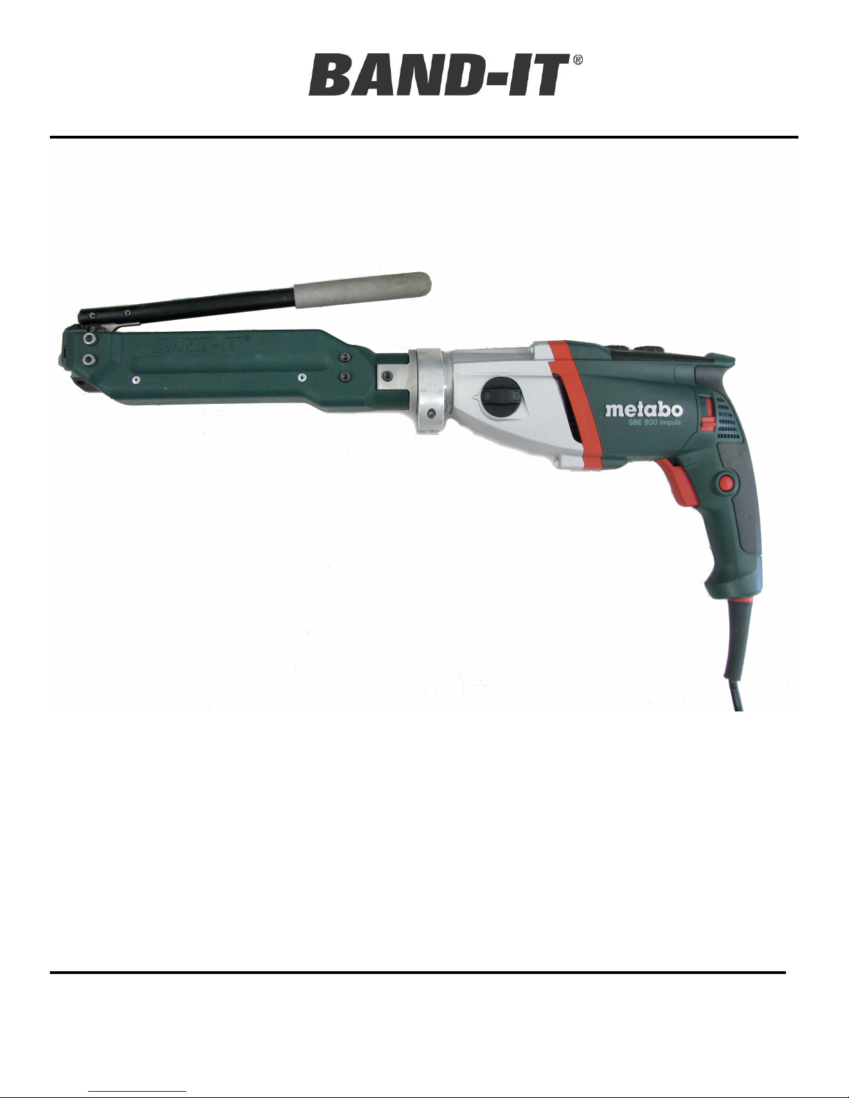
UL9010
Ultra-Lok
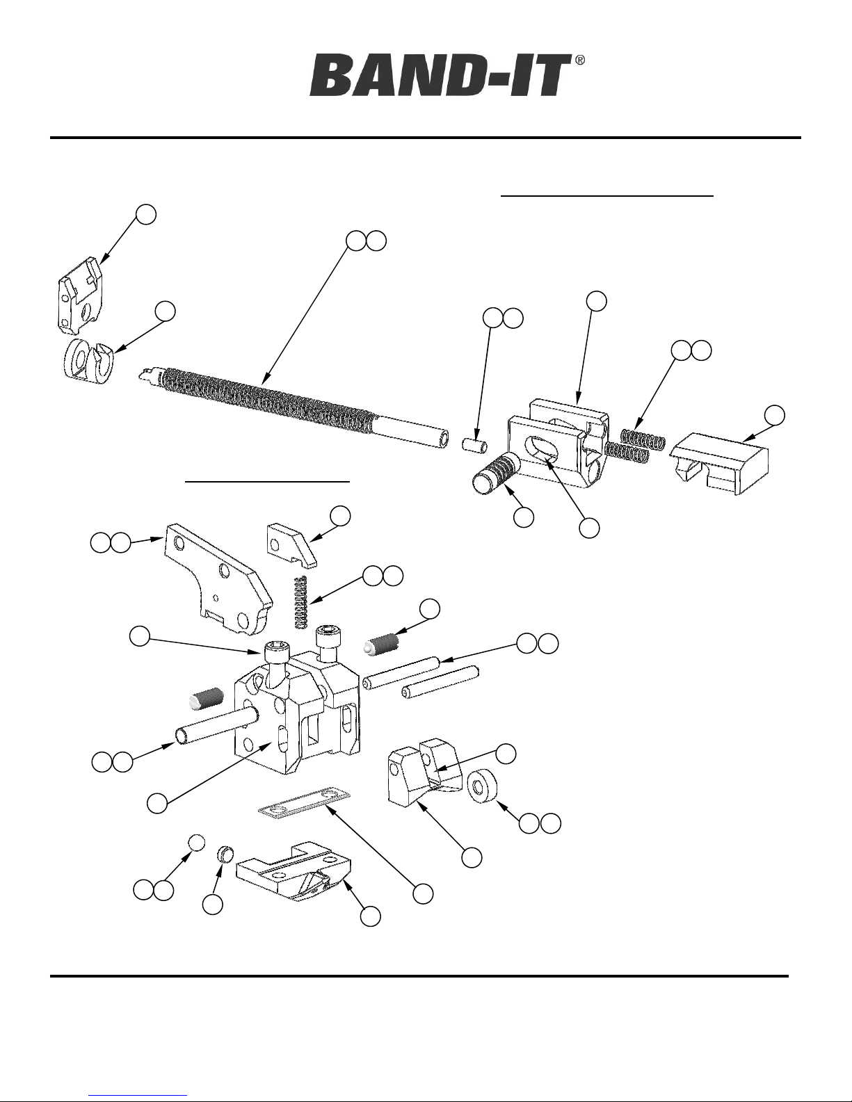
Tool
Parts List
Notes:
Apply Item 31 (Grease) to:
Item 4 (Cut off cam)
Item 3 (Cutter knife) at contact point with item 1 (Tool head)
Item 26 (Spring) before installation
Apply Item 32 (Grease) to:
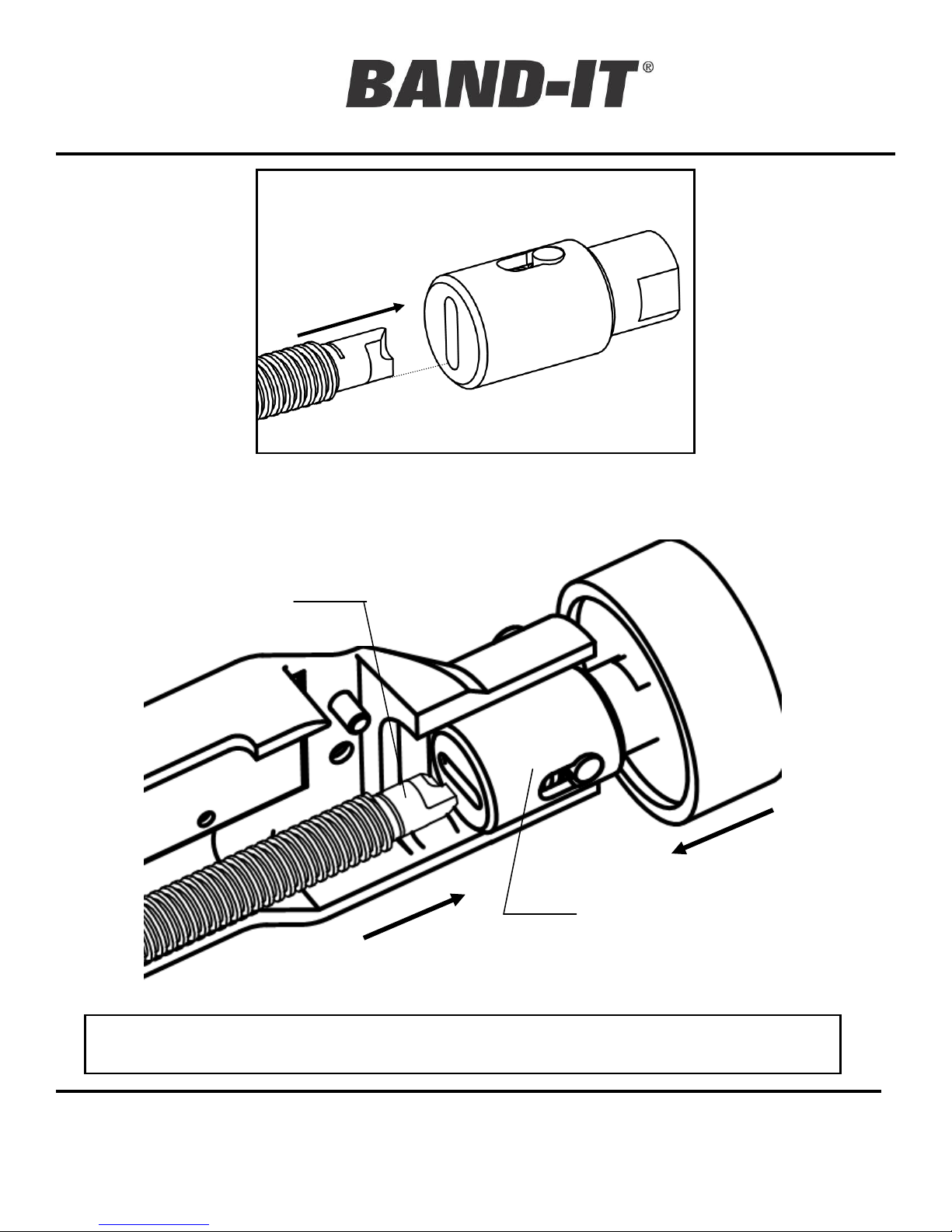
Item 7 (Tension screw) threads and grooved end
Item 2 (Cutter blade) counter-bore only, after item 14 (bearing tip) has been installed.
Tighten the following:
Item 23 (#10-32 Screws)
to 60 – 70 in-lbs.
Item 22 (1/4-28 Screws)
to 90 – 110 in-lbs.
Adjust Item 24 (Plunger) for
positive detent action when
item 6 (Handle) is actuated.
Part M09887, Shear Plate has
two cutting edges. This part
can be rotated to use the second
edge prior to replacement.
NOTE:
Part M09387, (Optional)
½” Shear Plate -
Required replacement for # 33
M09887 shear plate in order to
install ½” wide Ultra-Lok
Clamps
Item Part Number Quantity Description
1 M00587 1 Tool Head, Fin. UL
2 M09787 1 Cutter Blade, UL
3 M08687 1 Cutter Knife, UL
4 M08987 1 Cam, Cut-off, UL
5 M09087 1 Tension Block, Mach., UL
6 UL1219 1 Handle Assembly: Includes Handle, Handle
Grip, and Pins
7 M00987 1 Tension Screw, Fin.
8 M08887 1 Gripper, UL
9 M01787 1 Plate, Back, Cast/Fin.
10 M09187 1 Gripper Guide, UL
11 M02387 1 Plate, Release, cast/fin.
12 M00287 1 Roller, Cut-off, Fin.
13 M01388 1 Pin, .187 Dia X 1.50 Long, Fin.
14 M05387 1 Bearing Tip, Fin.
15 M06587 1 Ball, ¼” Diameter
16 M02287 1 Tip, Load Bearing, Fin.
17 M04387 1 Tripper Bracket, Cast/Fin.
18 M07387 1 Body, Left, Finished, UL
19 M07487 1 Body, Right, Finished, UL
20 M07587 2 Wear Plate, Fin.
21 M05787 2 Screw, Socket Head Cap, ¼ X 1”
22 J67287 4 Screw, Socket Head Cap, ¼ X ½”
23 M06187 4 Screw, Socket Head Cap, #10-32 X 3/8”
24 M02487 2 Screw, Spring Plunger, ¼-20
25 A33887 1 Spring, Compression, .180 X .813 Long
26 A53587 2 Spring, Compression, .300 X 1.00 Long
27 M01487 1 Pin, Dowel, ¼ Dia X 1.50 Long
28 M08187 4 Washer, .128 ID X .238 OD
29 M08087 4 Rivet, Blind, .125 X .328 Long
30 M07987 2 Threaded Insert, #10-32
31 I16387 - Lubricant, Super Lube w/ Teflon
32 C23199 - Lubricant, Moly, Syringe
33 M09887 1 Shear Plate, ¾”, UL
34 M09387 1 Shear Plate, ½”, UL (Optional)
35 M07687 1 Tool Adapter #1
36 M08288 1 Adapter Clamp