manuals.online logo
Brands
  1. Home
  2. •
  3. Brands
  4. •
  5. Banner
  6. •
  7. Accessories
  8. •
  9. Banner SLU4 User manual

Banner SLU4 User manual

Quick Start Guide
Ultrasonic Label Sensors for Detection of Clear Labels
This guide is designed to help you set up and install the SLU4 Slot Sensor. For complete information on programming, performance,
troubleshooting, dimensions, and accessories, please refer to the Instruction Manual at www.bannerengineering.com. Search for p/n 230091 to view
the Instruction Manual. Use of this document assumes familiarity with pertinent industry standards and practices.
WARNING:
•Do not use this device for personnel protection
• Using this device for personnel protection could result in serious injury or death.
• This device does not include the self-checking redundant circuitry necessary to allow its use in personnel safety
applications. A device failure or malfunction can cause either an energized (on) or de-energized (off) output condition.
Models
Model Supply Voltage Output Type Connection
SLU4-PN-2M
12 V DC to 30 V DC Bipolar NPN/PNP
1.8 m (6 ft) unterminated 5-wire PVC cable
SLU4-PN-Q8 Integral 5-pin M12 male quick-disconnect connector
SLU4-PN-Q7 Integral 4-pin M8 male quick-disconnect connector
SLU4-BM-Q7 Selectable NPN or PNP
Features and Indicators
134
25
1. Output indicator
2. Display
3. (GAP/2PT/DYN)(+)
4. (TEACH)(SELECT)
5. (MODE)(-)
Output Indicator
• Amber LED illuminates when outputs are ON
• Flashes when short circuit or overload detected
Display
Use the display to view menu options and other information.
Figure 1. Display in Run Mode
1
2
3
4
5
6
1. Signal strength
2. Contrast indicator (0 to 9)
3. Threshold number
4. Output in gap or on label
5. Button lock or unlock
6. Auto adjust on/off (AUTO)
Buttons
Use the sensor buttons to program the sensor.
(GAP/2PT/DYN)(+)
• Press and hold for 2 seconds to access and select
different TEACH methods
• Press to increase the contrast threshold value
• Scroll through settings in the menu
• Manually adjust the threshold number while in Run
mode
(TEACH)(SELECT)
• Press and hold for 2 seconds to initiate the TEACH
process
• Select settings in MENU options
(MODE)(-)
• Press and hold for 2 seconds to access the menu
• Scroll through settings in the menu
• Manually adjust the threshold number while in Run
mode
SLU4 Slot Sensor
Original Document
225944 Rev. B | 070-0702 9 September 2022
225944
Installation
Mount the Sensor
Mount the SLU4 directly and securely using the clearance holes on the side of the sensor (bolts not included).
To lessen the effects of web flutter, position the bottom fork of the sensor slightly above the path of the web so that the web can glide over the
bottom of the fork with slight tension.
Wiring
Figure 2. M8 Models—bimodal with remote input
bk (4)
bn (1)
bu (3)
wh (2)
12–30 V DC
CH1
+
–
Load
Remote Teach
The black wire is selectable NPN or PNP via the
menu. This selection causes the remote input to
be active low or active high.
Figure 3. M8 model, bipolar
bu (3)
bn (1)
wh (2)
bk (4)
12-30V DC
Load
Load
+
–
Figure 4. M8 Male Connector
3
2
1
4
1. Brown
2. White
3. Black
4. Blue
Figure 5. M12 and cabled models—bipolar with remote input
Remote TEACH
bu (3)
bn (1)
wh (2)
bk (4)
gy (5)
12-30V DC
Load
Load
+
–
Figure 6. M12 Male Connector
1
4
5
3
2
1. Brown
2. White
3. Blue
4. Black
5. Gray
Sensor Setup
Use the following images and instructions to program the sensor for use.
The default TEACH mode is Gap TEACH.
Gap TEACH
The sensor sets a threshold based on the gap between two labels.
1. Place the label web so that it is centered on the arrow.
Figure 7. Align Label to Arrow
Optical Path
Alignment Mark
2. Position the gap between the labels in the center of the sensor using the alignment line as shown.
When viewing from the top of the sensor, use the output LED to center the gap between the labels.
Figure 8. Align Gap to Line
Optical Path
Alignment Mark
SLU4 Slot Sensor
2 www.bannerengineering.com - Tel: + 1 888 373 6767 P/N 225944 Rev. B | 070-0702
Note: For a simpler TEACH, remove one label to create a larger gap.
3. Place label webbing so that it slides along the bottom of the sensor gap plate.
This ensures a more consistent setup and performance.
4. Press and hold the TEACH button for 2 seconds.
The display shows "Gap Set", then returns to Run mode.
The + and - buttons can be used to manually fine tune the sensor to the application.
Sensor Menu
Access the menu from run mode by pressing and holding MODE for 2 seconds.
Use +and –buttons to navigate through the menu. Press SELECT to select a menu option and access the submenus. Use +and –to navigate
through the submenus. Press SELECT to select a submenu option and return to the top menu or press and hold SELECT for longer than 2 seconds
to select a submenu option and return immediately to run mode.
To exit Setup mode and return to Run mode, navigate to End and press SELECT.
The following are menu options:
Adaptive Tracking
Evaluates signal levels and makes automatic adjustments to keep the sensor in optimum response levels.
Output Mode
Change from GAP ( ) to LABEL ( ). GAP means the output will be on when the label is not present under the transducer. LABEL
means the output will be on when the label is under the transducer.
= Outputs on the Label
= Outputs in the Gap
Display Orientation
Toggles the orientation of the display.
Timer Mode
Selects the output timing delay to be set:
Off Delay—Outputs stay on for set time after duration of input.
On Delay—Outputs turn on when input exceeds set time.
One Shot—Outputs turn on for set time when triggered by input.
Debounce—Output changes immediately when a change in detect state occurs. Then, a timer prevents the output from switching
again until the timer expires. This behavior occurs on both the leading and trailing edges of the object.
Figure 9. Output Timing Delays
Output
OFF Delay
ON Delay
Time
1-Shot
ON
OFF
D
D
D
D
Debounce
Timer
Timer
Start
Timer
Expired
D D
(D = 1ms - 90.0s)
Timer
Start
Timer
Expired
Timer
Start
Timer
Expired
Timer
Start
Timer
Expired
Timer Value
Sets the delay timer. This menu item is available only if a Timer Mode has been selected. The range is 1 ms to 9999 ms.
Button Lockout
Locks the sensor for tamper-free operation.
The sensor can be taught if it is locked. To unlock the sensor, toggle from Lock ( ) to Unlock (no symbol).
Scope
Allows the operator to visually inspect the current setup for repeatability. The sensor scope also reveals any nominal setup issues or
sensitivities to label or gap thickness changes. To shorten the time between signals, press +. To lengthen the time between signals, press
–.
Input Active (SLU4-PN-2M and SLU4-PN-Q8 models only)
Sets the remote input to either Active High or Active Low to dictate the type of signal needed to program the sensor remotely. For more
details, see Remote Input on page 4.
Input/Output (SLU4-BM-Q7 model only)
Sets the output to either NPN or PNP. Also sets the remote input to either Active High or Active Low to dictate the type of signal needed to
program the sensor remotely. For more details, see Remote Input on page 4.
End
Returns to run mode.
SLU4 Slot Sensor
P/N 225944 Rev. B | 070-0702 www.bannerengineering.com - Tel: + 1 888 373 6767 3
Factory Reset
Resets the sensor to factory defaults.
Remote Input
Use the remote input to program the sensor remotely.
The remote input provides limited programming options. The remote input is either Active High (PNP) or Active Low (NPN) depending on the Input
Active setting. For Active High (PNP), connect the white wire to 24 V DC with a remote switch connected between the wire and 24 V DC. For Active
Low, connect the white wire to ground (0 V DC) with a remote switch connected between the wire and ground. Pulse the remote input according to
the diagram and the instructions provided in this manual.
The length of the individual programming pulses is equal to the value T: 0.04 seconds ≤ T ≤ 0.4 seconds.
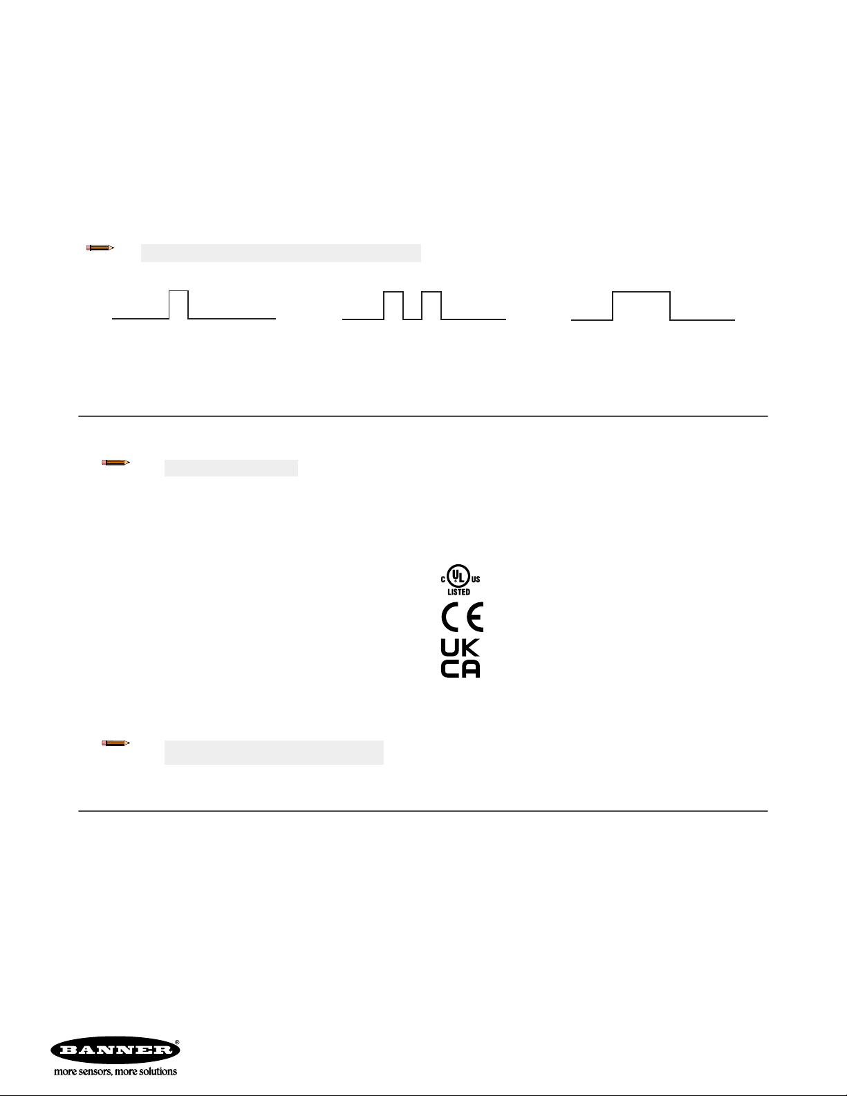
Remote Input Signals
Note: Waveforms shown correspond to PNP input mode.
Figure 10. Gap Set
Pulse once, 40 ms to 400 ms.
Figure 11. Label Set
Pulse twice, 40 ms to 400 ms, with 40 ms to
400 ms idle time between pulses.
Figure 12. Dynamic Set
Hold the remote input on for more than 750 ms,
while pulling the labels and gaps through the
sensor, then release the remote input line. The
sensor returns to Run mode.
Specifications
Supply Voltage and Current
12 V DC to 30 V DC
Polarity Protected
Note: For use in Class 2 circuits
95 mA at 12 V DC, 45 mA at 30 V DC
Digital Outputs
(1) NPN and (1) PNP open collector output 150mA maximum; <2 V residual voltage
On SLU4-BM-Q7, NPN & PNP are user-selectable
Protected against output short-circuit
Remote TEACH Input
Momentary sinking or sourcing input;1.2 mA maximum; software selectable
Hysteresis
Dynamic, adjusted by TEACH
Response Time
200 μs
Repeatability
125 μs
Threshold Set
1-Point, 2-Point, or Dynamic TEACH; manually or remotely
Threshold Adjust
Manual or AUTO adjust
Output Timers
On Delay, Off Delay, One Shot, or Debounce
Slot Width
4 mm
Indicators
Display: Includes contrast indicator, numerical display, set point and trigger point, and
all sensor options and modes
Amber LED output indicator: Illuminates when the sensor’s output transistors are ON
Note: Note: If output LED flashes on power up, a short
circuit condition exists.
Construction
Chemical resistant, high impact aluminum housing
Conforms to heavy industry grade CE requirements
Connection
Integral 5-pin M12 male quick-disconnect connector, Integral 4-pin M8 male quick-
disconnect connector, or 1.8 m (6 ft) unterminated 5-wire PVC cable, depending on
model
Environmental Rating
NEMA 4X, NEMA 6P, and IP65
Ambient Temperature
+4 °C to +50 °C (+39 °F to +122 °F)
Certifications
RoHS compliant
Banner Engineering Europe Park
Lane, Culliganlaan 2F bus 3, 1831
Diegem, BELGIUM
Turck Banner LTD Blenheim House,
Blenheim Court, Wickford, Essex
SS11 8YT, Great Britain
Banner Engineering Corp. Limited Warranty
Banner Engineering Corp. warrants its products to be free from defects in material and workmanship for one year following the date of shipment. Banner Engineering Corp. will repair or replace, free of charge,
any product of its manufacture which, at the time it is returned to the factory, is found to have been defective during the warranty period. This warranty does not cover damage or liability for misuse, abuse, or the
improper application or installation of the Banner product.
THIS LIMITED WARRANTY IS EXCLUSIVE AND IN LIEU OF ALL OTHER WARRANTIES WHETHER EXPRESS OR IMPLIED (INCLUDING, WITHOUT LIMITATION, ANY WARRANTY OF MERCHANTABILITY OR
FITNESS FOR A PARTICULAR PURPOSE), AND WHETHER ARISING UNDER COURSE OF PERFORMANCE, COURSE OF DEALING OR TRADE USAGE.
This Warranty is exclusive and limited to repair or, at the discretion of Banner Engineering Corp., replacement. IN NO EVENT SHALL BANNER ENGINEERING CORP. BE LIABLE TO BUYER OR ANY OTHER
PERSON OR ENTITY FOR ANY EXTRA COSTS, EXPENSES, LOSSES, LOSS OF PROFITS, OR ANY INCIDENTAL, CONSEQUENTIAL OR SPECIAL DAMAGES RESULTING FROM ANY PRODUCT DEFECT OR
FROM THE USE OR INABILITY TO USE THE PRODUCT, WHETHER ARISING IN CONTRACT OR WARRANTY, STATUTE, TORT, STRICT LIABILITY, NEGLIGENCE, OR OTHERWISE.
Banner Engineering Corp. reserves the right to change, modify or improve the design of the product without assuming any obligations or liabilities relating to any product previously manufactured by Banner
Engineering Corp. Any misuse, abuse, or improper application or installation of this product or use of the product for personal protection applications when the product is identified as not intended for such
purposes will void the product warranty. Any modifications to this product without prior express approval by Banner Engineering Corp will void the product warranties. All specifications published in this
document are subject to change; Banner reserves the right to modify product specifications or update documentation at any time. Specifications and product information in English supersede that which is
provided in any other language. For the most recent version of any documentation, refer to: www.bannerengineering.com.
For patent information, see www.bannerengineering.com/patents.
SLU4 Slot Sensor
©Banner Engineering Corp. All rights reserved

This manual suits for next models

4

Other Banner Accessories manuals

Banner WORLD-BEAM QS18 Expert Series User manual

Banner

Banner WORLD-BEAM QS18 Expert Series User manual

Banner D10 Expert Series User manual

Banner

Banner D10 Expert Series User manual

Banner Q5X User manual

Banner

Banner Q5X User manual

Banner Q4X Series User manual

Banner

Banner Q4X Series User manual

Banner PresencePLUS P1B65Q User manual

Banner

Banner PresencePLUS P1B65Q User manual

Banner World-Beam QS30 User manual

Banner

Banner World-Beam QS30 User manual

Banner Q5X User manual

Banner

Banner Q5X User manual

Banner iVu PLUS TG User manual

Banner

Banner iVu PLUS TG User manual

Banner Q3X User manual

Banner

Banner Q3X User manual

Banner iVu Plus User manual

Banner

Banner iVu Plus User manual

Banner L-GAGE LE250 IO-Link User manual

Banner

Banner L-GAGE LE250 IO-Link User manual

Banner R-Gage Q130RA-AF User manual

Banner

Banner R-Gage Q130RA-AF User manual

Banner R-GAGE Q240RA-AF2 User manual

Banner

Banner R-GAGE Q240RA-AF2 User manual

Banner L-GAGE LE250 IO-Link User manual

Banner

Banner L-GAGE LE250 IO-Link User manual

Banner T30RW User manual

Banner

Banner T30RW User manual

Banner Q5X User manual

Banner

Banner Q5X User manual

Banner U-Gage Ultrasonic Sensor User manual

Banner

Banner U-Gage Ultrasonic Sensor User manual

Banner TCNM-ACM-OM110 User manual

Banner

Banner TCNM-ACM-OM110 User manual

Banner M12 User manual

Banner

Banner M12 User manual

Banner DF-G1 Expert User manual

Banner

Banner DF-G1 Expert User manual

Banner Q25 User manual

Banner

Banner Q25 User manual

Banner ZMX Series User manual

Banner

Banner ZMX Series User manual

Banner iVu Plus BCR User manual

Banner

Banner iVu Plus BCR User manual

Banner L-GAGE LE250 IO-Link User manual

Banner

Banner L-GAGE LE250 IO-Link User manual

Popular Accessories manuals by other brands

Leviton Decora ODS06 Product data

Leviton

Leviton Decora ODS06 Product data

Smeg 3761 Gebrauchsanweisung

Smeg

Smeg 3761 Gebrauchsanweisung

Lanaform Noumea Instructions for use

Lanaform

Lanaform Noumea Instructions for use

logika WL-ZSPDBPW-MT-02 product manual

logika

logika WL-ZSPDBPW-MT-02 product manual

Velux MIE installation instructions

Velux

Velux MIE installation instructions

Philips Norelco 7100 series user manual

Philips

Philips Norelco 7100 series user manual

Omron E3Z series manual

Omron

Omron E3Z series manual

Konyks Pluviose Easy EU quick start

Konyks

Konyks Pluviose Easy EU quick start

arpal GULF SUPERNOVA SN35 PRODUCT GUIDANCE SHEET

arpal GULF

arpal GULF SUPERNOVA SN35 PRODUCT GUIDANCE SHEET

Omron E2K-L quick start guide

Omron

Omron E2K-L quick start guide

Leviton Lumina LURPC-00W manual

Leviton

Leviton Lumina LURPC-00W manual

Pentel Otenznero quick start guide

Pentel

Pentel Otenznero quick start guide

SCENTED INTERIORS BY DESIGN MINI 150 user guide

SCENTED INTERIORS BY DESIGN

SCENTED INTERIORS BY DESIGN MINI 150 user guide

Chauvin Arnoux MN93 user manual

Chauvin Arnoux

Chauvin Arnoux MN93 user manual

netvox R718PA2 user manual

netvox

netvox R718PA2 user manual

Orno OR-DB-LT-126 Operating and instalation instructions

Orno

Orno OR-DB-LT-126 Operating and instalation instructions

NATURE & DECOUVERTES 15225550 manual

NATURE & DECOUVERTES

NATURE & DECOUVERTES 15225550 manual

Canyon PB-202 quick guide

Canyon

Canyon PB-202 quick guide

manuals.online logo
manuals.online logoBrands
  • About & Mission
  • Contact us
  • Privacy Policy
  • Terms and Conditions

Copyright 2025 Manuals.Online. All Rights Reserved.