Banner DXM700 User manual

Pick-to-Light Solutions Guide
Instruction Manual
Original Instructions
214046 Rev. A
14 November 2019
©Banner Engineering Corp. All rights reserved
214046

Contents
1 Product Overview ............................................................................................................................................................ 3
1.1 Definition of PICK-IQ™................................................................................................................................................................... 3
1.2 Understanding the Application Control ........................................................................................................................................... 3
1.3 Features ........................................................................................................................................................................................... 4
1.4 Solution Components ...................................................................................................................................................................... 4
1.4.1 DXM700 ...................................................................................................................................................................................4
2 Compatible Hardware .....................................................................................................................................................6
2.1 PTL110 .............................................................................................................................................................................................6
3 Configuration Instructions .............................................................................................................................................. 7
3.1 Initialization Modes ......................................................................................................................................................................... 7
3.1.1 Assign a Single Device ID .........................................................................................................................................................8
3.1.2 Assign Multiple Device IDs .......................................................................................................................................................8
3.1.3 Connectivity Test Mode ........................................................................................................................................................... 8
3.1.4 Clear Mode ...............................................................................................................................................................................8
3.2 Using the Read/Write Registers Operation ......................................................................................................................................8
3.2.1 Examples .................................................................................................................................................................................9
4 Operating Modes ...........................................................................................................................................................10
4.1 Teach Mode ..................................................................................................................................................................................11
4.2 Sequence Pick Mode .....................................................................................................................................................................11
4.3 Batch Pick Mode .......................................................................................................................................................................... 11
4.4 Host Load List ................................................................................................................................................................................11
4.5 Compact List ................................................................................................................................................................................ 12
4.6 File SbFile1.dat ............................................................................................................................................................................. 12
5 Accessories ................................................................................................................................................................... 13
5.1 Cordsets ........................................................................................................................................................................................ 13
6 Product Support and Maintenance .............................................................................................................................. 15
6.1 Recommended Resources ............................................................................................................................................................ 15
6.2 Contact Us .....................................................................................................................................................................................15
6.3 Banner Engineering Corp. Limited Warranty ................................................................................................................................ 15
6.4 Banner Engineering Corp. Software Copyright Notice ..................................................................................................................15
6.5 FCC Part 15 and CAN ICES-3 (B)/NMB-3(B) .................................................................................................................................16
Pick-to-Light Solutions Guide

1 Product Overview
The Pick-to-Light Solutions Guide uses a ScriptBasic program and application specific XML developed by Banner to
quickly integrate a system without the need to have an advanced understanding of programming methods.
1.1 Definition of PICK-IQ™
The Pick-to-Light Solutions Guide allows users to interface with PICK-IQ ™products. PICK-IQ™is a modified usage of the
Modbus RTU protocol that allows for quick responses in large serial networks. Each Pick-to-Light device is assigned a
common ID and a unique Device ID. This allows a unique device to be written with specific information, but a controller to
only monitor a single ID point for the speed of a two-node network.
1.2 Understanding the Application Control
Pick-to-Light, also known as light-directed or light-guided picking, refers to the use of colored LED indicators to guide
assemblers and operators to the correct part or product location. Pick-to-Light solutions can also be used to indicate the
number of parts to pick and proper pick order.
These solutions make manual picking processes faster and more accurate in a wide variety of applications including
assembly, kitting, and order fulfillment.
The four main states of a pick device are:
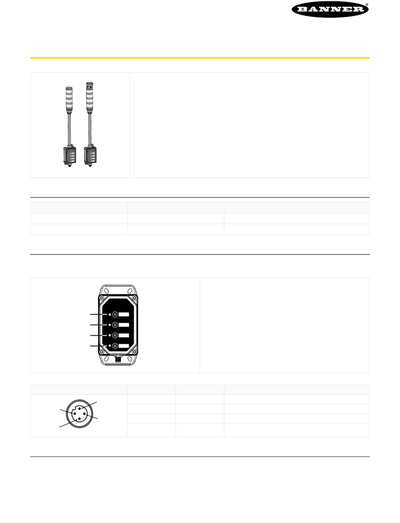
Figure 1. PTL110 Pick-to-Light Sensor
Wait State
The device is either inactive or the bin is not selected in the
current pick group (default = color and animation off).
Mispick State
While in Wait State, when the primary or secondary sensor
becomes active, the state changes to Mispick after the on-delay
is met, and stays on for the duration of the sensor actuation.
Mispick on-delay is used to filter unintended activations (default
= red flash).
Job State
When the Job Status is not zero, the individual device goes into
the Job State, indicating that it is in the current pick routine.
Animation, color, intensity, speed, pattern, and direction are
controlled for maximum efficiency (default = green steady).
Acknowledge State
The Acknowledge State is activated when either of the sensors
are actuated in the Job State. A secondary Acknowledge State
(2) is included to distinguish between touch and optical sensor
interaction (default = yellow steady).
Primary Output Logic Tables
Job Input Logic Touch or Sensor Not Activated Touch or Sensor Activated
Not Active Wait State Mispick State
Active Job State Acknowledge State
Pick-to-Light Solutions Guide
www.bannerengineering.com - Tel: + 1 888 373 6767 3

Pick-to-Light
Sequence Initiated
Is the device on the
active pick list?
Job State
Device
Actuated
Acknowledge
State
YES NO Wait State Device
Actuated
Mispick State
Figure 2. Pick-to-Light Flowchart
1.3 Features
• Operator tasks are integrated at the device level
• Multiple methods to access and control registers to allow
integrations across platforms
◦Modbus RTU
◦Ethernet TCP/IP
◦Ethernet/IP
◦Direct API connection
◦Cloud Interface
• All the device level logic is written and tested; user is
focused on higher level data aggregation out of the box
• Ability to store 256 recipes for a pick station or to configure
them spontaneously
• Allows for a sequential or batch picking mode
• Easily assign Device IDs with flexibility for moves, adds, and
changes
• Touch and optical sensor interactions can be uniquely
identified to provide dual functionality
1.4 Solution Components
1.4.1 DXM700
Figure 3. DXM700-B1-PTL
The DXM700 Controller with the ScriptBasic Solution
completes all of the low-level logic for a Pick-to-Light device
and provides access to supervisory systems. The internal
Modbus master controls the main Pick-to-Light network,
while the interface to the control system is either through an
ethernet port or a high-speed serial port.
Model Description
DXM700-B1-PTL Pre-Programmed DXM700 for Pick-to-Light Integration
Pick-to-Light Solutions Guide
4 www.bannerengineering.com - Tel: + 1 888 373 6767

B1 =
Radio Configuration
B1
Base
DXM700- R1
Modbus controller for data aggregation of
sensors and wireless networks
Power: 12−30 V dc
Comms: RS-485, Secondary RS-485
Outputs: Four PNP
Blank = None
R1 = 900 MHz, 1 W PE5 Performance Radio (North America)
R2 = 900 MHz, 1 W HE5 MultiHop Data Radio (North America)
R3 = 2.4 GHz, 65 mW PE5 Performance Radio (Worldwide)
R4 = 2.4 GHz, 65 mW HE5 MultiHop Data Radio (Worldwide)
R5 = 900 MHz, 65 mW HE5L MultiHop Data Radio (Used for M-GAGE networks)
PTL = Pre-Programmed DXM700 for Pick-to-Light Integration
Reference the following documents for further information about the DXM700:
DXM700-B1 Wireless Controller Datasheet Original document PN 207893
DXM700-Bx Wireless Controller Instruction Manual Original document PN 207894
Pick-to-Light Solutions Guide
www.bannerengineering.com - Tel: + 1 888 373 6767 5
Table of contents
Other Banner Lighting Equipment manuals

Banner
Banner EZ-STATUS WLS27 Series User manual

Banner
Banner LS Basic User manual

Banner
Banner TL50 Pro Series User manual

Banner
Banner EZ-SCREEN LP User manual

Banner
Banner PTL110S User manual

Banner
Banner TL70 User manual

Banner
Banner TL50 User manual

Banner
Banner A-GAGE MINI-ARRAY User manual

Banner
Banner EZ-STATUS WLS27 Series User manual

Banner
Banner K50RPLPGRYC3QPMA User manual