Banner TL50 Pro Series User manual

Datasheet
50 mm Programmable Multicolor RGB Tower Light
Standard Compact Beacon
Standard
Audible
Sealed
Audible
Omni-Directional
Sealed Audible
• Rugged, cost-effective, and easy-to-install multi-segment tower lights
• Programmable using Banner's Pro Editor software and Pro Converter Cable
• Illuminated segments provide easy-to-see operator guidance and indication of
equipment status
• Up to 7 segments available
• Available in black or light gray housing to match different machine styles
• Audible models available with standard, sealed, or omni-directional audible element
• Compact and beacon models are more intense in a smaller form factor compared to
standard models
• 10 V DC to 30 V DC operation
• Bimodal inputs (PNP/NPN), depending on source wiring
Models
TL50
Connector
Audible
Number of
Segments
StyleFamily
P = Pro 1 = 1 Segment
2 = 2 Segments
3 = 3 Segments
4 = 4 Segments
5 = 5 Segments
6 = 6 Segments
7 = 7 Segments *
Blank = None (IEC IP67)
A = Audible (IEC IP50)
ALS = Sealed Audible Continuous Tone
AOS = Omni-Directional Sealed Audible
Continuous Tone Q = 5-pin or 8-pin M12 QD
Housing
Color
Blank = Black
C = Cool Gray
AOSI = Omni-Directional Sealed Audible
Continuous Tone with Intensity Adjust
3AQ
QP = 150 mm cable with a 5-pin
or 8-pin M12 QD
P
Housing
Blank = Standard
C = Compact
BL = Beacon
C
* Not available with audible
Blank = 2 m integral cable
TL50 Pro models without audible have a 5-pin M12 quick disconnect for one through four segments and have an 8-pin M12 quick
disconnect for five to seven segments. Models with an audible segment have a 5-pin M12 quick disconnect for one through three
segments and have an 8-pin M12 quick disconnect for four through six segments.
Configuration Instructions
Pro Editor
Use Banner's Pro Editor software and Pro Converter Cable to create custom
configurations by selecting different colors, flash patterns, and animations.
For more information visit www.bannerengineering.com/proeditor.
TL50 Pro Tower Light
Original Document
209142 Rev. D
19 October 2021
209142

Full Preview Connection (Recommended)
The full preview connection must be used for the TL50 Pro Tower Light, the K90 Pro Indicator, and for Pro-series Strip Lights, and is
optional but recommended for other Pro-series enabled devices.
A
B
C
E
D
F
A = Pro Converter Cable (MQDC-506-USB)
B = Splitter (CSB-M1251FM1251M)
C = PC running Pro Editor software
D = Any Banner Pro Series-enabled device (K50 shown)
E = Power Supply (PSW-24-1 or PSD-24-4)
F = 8-Pin to 5-Pin Double-Ended Cordset (MQDC-801-5M-PRO),
required for 8-Pin models
Default Segment Colors
Number of Segments Colors (Bottom to Top)
1 Red
2 Green, Red
3 Green, Yellow, Red
4 Blue, Green, Yellow, Red
5 White, Blue, Green, Yellow, Red
6 Orange, White, Blue, Green, Yellow, Red
7 Magenta, Orange, White, Blue, Green, Yellow, Red
Wiring Diagrams
Note: All models are bimodal and can be wired as PNP or NPN devices.
5-pin/Wire Models
3
4
1
2
5
10–30 V dc
or
S4/A
S2
S3
S1
Audible
S1 = Segment 1
S2 = Segment 2
S3 = Segment 3
S4 = Segment 4
A = Audible
1
4
5
3
2
Pin Color Segment Mode Advanced Mode
3 blue Common Common (PNP) or 10–30 V DC (NPN)
4 black Segment 1 Reset Input
1 brown Segment 2 10–30 V DC (PNP) or Common (NPN)
2 white Segment 3 PWM, PFM, Counter, or Timer input
5 gray Segment 4/Audible N/A
TL50 Pro Tower Light
2 www.bannerengineering.com - Tel: + 1 888 373 6767 P/N 209142 Rev. D

8-pin/Wire Models
7
6
2
1
5
10–30 V dc
or
4
3
Audible
S2
S3
S1
S4
S5
8
S6
S7/A
S1 = Segment 1
S2 = Segment 2
S3 = Segment 3
S4 = Segment 4
S5 = Segment 5
S6 = Segment 6
S7 = Segment 7
A = Audible
5
6
7
1
8
2
3
4
Pin Color Segment Mode Advanced Mode
7 blue Common Common (PNP) or 10–30 V DC
(NPN)
6 pink Segment 1 Reset Input
2 brown Segment 2 10–30 V DC (PNP) or Common
(NPN)
1 white Segment 3 PWM, PFM, Counter, or Timer input
5 gray Segment 4 N/A
4 yellow Segment 5 N/A
8 red Segment 6 N/A
3 green Segment 7/Audible N/A
Pro Editor Configuration for the TL50 Pro
Banner's Pro Editor software offers an easy way to configure Pro Series-enabled touch and indicator devices, allowing users full
control of device states. The easy-to-use configuration software provides a variety of tools and capabilities to solve a wide range of
applications. Pro Editor includes a preview mode that allows users to verify device performance before writing a configuration to a
device. Configure any Pro Series-enabled device using the free Pro Editor software, available for download at
www.bannerengineering.com/proeditor.
Segment Mode—Use Segment Mode to activate each segment and to control the input wire, color, animation, intensity, and speed.
In Segment Mode, enable the Action Input to switch between Segment Mode and Run Mode (all segments) animations depending
on wiring. The combination of the Action Input and the Segment input controls all tower light segments at once.
Segment Mode
Animation
Description
Off Segment is off
Steady Color 1 is on at defined intensity
Flash Color 1 flashes at defined speed, color intensity, and pattern (normal, strobe, three pulse, SOS, or random)
Two Color Flash Color 1 and Color 2 flash alternately at defined speed, color intensities, and pattern (normal, strobe, three pulse, SOS, or random)
50/50 Color 1 is displayed on 50% of the segment and Color 2 is displayed on the other 50% of the segment at the defined color intensities
50/50 Rotate Color 1 is displayed on 50% of the segment and Color 2 is displayed on the other 50% of the segment while rotating at the defined speed,
color intensities, and rotational direction
Chase Color 1 is displayed as a single spot against the background of Color 2 while rotating at the defined speed, color intensities, and rotational
direction
Intensity Sweep Color 1 repeatedly increases and decreases intensity between 0% to 100% at defined speed and color intensity
Run Mode—Use the TL50 Pro's Run Mode to control the entire tower light and to control the input wire, color, animation, intensity,
and speed. Run Mode with a larger assigned run number overrides the lower assigned run numbers.
Run or Action Mode
Animation
Description
Off All tower light segments are off
Steady Color 1 is solid on for every tower light segment at defined intensity
Flash Color 1 flashes on every tower light segment at defined speed, color intensity, and pattern (normal, strobe, three pulse, SOS, or random)
Two Color Flash Color 1 and Color 2 flash alternately on every segment at defined speed, color intensities, and pattern (normal, strobe, three pulse, SOS, or
random)
TL50 Pro Tower Light
P/N 209142 Rev. D www.bannerengineering.com - Tel: + 1 888 373 6767 3

Run or Action Mode
Animation
Description
50/50 Color 1 is displayed on 50% of every segment and Color 2 is displayed on the other 50% of every segment at the defined color intensities
and segment shift
50/50 Rotate Color 1 is displayed on 50% of every segment and Color 2 is displayed on the other 50% of every segment while rotating at the defined
speed, color intensities, rotational direction, and segment shift
Chase Color 1 is displayed as a single spot against the background of Color 2 while rotating at the defined speed, color intensities, rotational
direction, and segment shift
Intensity Sweep Color 1 repeatedly increases and decreases intensity between 0% to 100% on every segment at defined speed and color intensity
Scroll Color 1 fills two segments and those segments move in one direction up or down against the background of Color 2 at the defined speed,
color intensities, and rotational direction
Bounce Color 1 fills two segments and those segments move up and down between the top and bottom of the tower against the background of Color
2 at the defined speed, color intensities, and rotational direction
Color Spectrum The tower light scrolls through the 14 predefined colors with a different color on each segment at the defined speed, Color 1 intensity, and
rotational direction
Advanced Mode—Use Advanced Mode to set the value range, thresholds, colors, intensities, flash speeds, and animation types for
PWM, PFM, Counter, and Timer control inputs.
Advanced Mode
Parameters Description
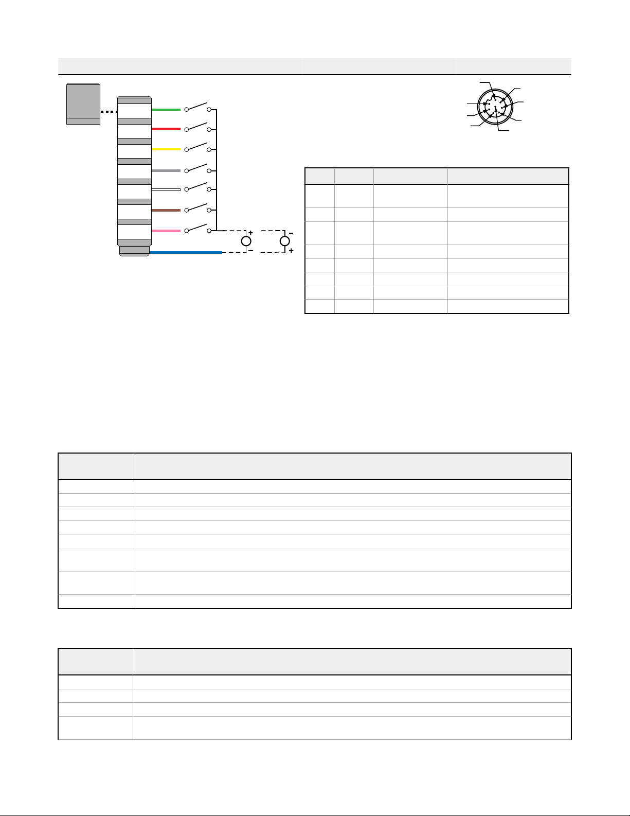
Control Type
PWM (Pulse Width Modulation): Apply a square wave signal to the PWM/PFM Input and vary the duty cycle from 0 to 100%
to set value. The signal must use a constant frequency between 100 to 10,000 Hz.
PFM (Pulse Frequency Modulation): Apply a square wave signal to the PWM/PFM Input and vary the frequency from 100 to
10,000 Hz to set the value. The signal must use a constant duty cycle from 10 to 90%.
Counter: Apply a single pulse to the Counter Input to change the value by 1. Apply a single pulse to the Reset Input to set the value to
the starting value, if enabled. The pulse signal must last a minimum of 16 ms; the value changes on the leading edge.
Timer: Apply constant power to the tower to change the value by 1 every 1 second. Use a constant on or off signal on the Timer Run
Input to start and pause the timer, respectively, if enabled. Apply a pulse to the Reset Input to set the value to the starting value, if
enabled. The pulse signal must last a minimum of 16 ms; the value changes on the leading edge.
Subsegment Style If the value is a partial percentage of a segment, select if segment will be on steady or analog dimmed to the partial percentage
Start From Top: The value decreases from the maximum value
Bottom: The value increases from the minimum value
Reset Input Apply a pulse signal to the Reset Input to set the value to the starting value, if enabled. The pulse signal must last a minimum of 16 ms.
Threshold Dominance Dominant: All segments display the active threshold color
Non-Dominant: Segments display their defined threshold color
Threshold Type:
Background A defined color and intensity is displayed on segments that are not active
Threshold Type: Base A defined animation state is displayed on segments that are not defined within a threshold
Threshold Type
≤: The animation state is displayed on the segments that are less than or equal to the defined threshold
≥: The animation state is displayed on the segments that are greater than or equal to the defined threshold
Disabled: The threshold is disabled
Global Parameters and
Advanced Settings Description
Orientation Standard: The tower base is down
Upside Down: The tower base is up
Background Color A defined color and intensity is displayed on segments that are not active
Animation Sync On: Segment animations align when any input state changes
Off: Segment animations will not be synchronized
Auto Restart On: The counter and timer will reset to the starting value after reaching the end value
Off: The counter and timer will stop at the ending value
Timer Run Input Use a constant on or off signal on the Timer Run Input to start and to pause the timer, respectively, if enabled
PFM/PWM Filter Level
Smooths the input signal by varying the sample size
Low: The sample size is short and changes to the input signal are more noticeable
High: The sample size is long and changes to the input signal are less noticeable
TL50 Pro Tower Light
4 www.bannerengineering.com - Tel: + 1 888 373 6767 P/N 209142 Rev. D

Global Parameters and
Advanced Settings Description
Hysteresis
Determines the signal value change needed to transition between thresholds and to prevent chatter
None: The value follows the input signal
High: A large value change is needed to transition between thresholds
Specifications
Supply Voltage and Current
10 V DC to 30 V DC
Maximum current per LED segment:
220 mA at 10 V DC
150 mA at 12 V DC
75 mA at 24 V DC
60 mA at 30 V DC
Maximum current for Standard Audible Alarm: 25 mA
Maximum current for Omni-Directional Sealed Audible: 45 mA
Maximum current for Sealed Audible Alarm: 35 mA
Supply Protection Circuitry
Protected against reverse polarity and transient voltages
Input Rating
Leakage Current Immunity: 400 uA
Indicator On/Off Response Time: 250 ms (maximum)
PWM Duty Cycle Range: 0 to 100%
PFM Frequency Range: 100 to 10000 Hz
Audible Adjustment
Standard Audible Alarm: Unscrew the cover (up to 1.5 turns maximum) to
adjust the audible intensity. (Do not exceed 1.5 turns or the cover may
detach during operation.) For maximum intensity, rotate the center plug 180°
counterclockwise to remove it.
Sealed Audible Alarm and Omni-Directional Sealed Audible Alarm with
Intensity Adjustment: Rotate the front cover until the desired intensity is
reached.
Omni-Directional Sealed Audible Alarm: No adjustment.
Audible Alarm
Standard Audible Alarm: 2.7 kHz ± 500 Hz oscillation frequency; maximum
intensity 92 dB at 1 m (3.3 ft) (typical)
Sealed Audible Alarm: 2.9 kHz ± 250 Hz oscillation frequency; maximum
intensity 94 dB at 1 m (3.3 ft) (typical)
Omni-Directional Sealed Audible Alarm: 2.1 kHz ± 250 Hz oscillation
frequency; maximum intensity 99 dB at 1 m (3.3 ft) (typical)
Omni-Directional Sealed Audible Alarm with Intensity Adjustment: 2.1
kHz ± 250 Hz oscillation frequency; maximum intensity 95 dB at 1 m (3.3 ft)
(typical)
Connections
5-pin or 8-pin integral M12 quick disconnect; 2 m (6.5 ft) integral PVC cable;
or a 150 mm (5.9 inch) PVC cable with a 5-pin or 8-pin M12 quick
disconnect, depending on model
Models with a quick disconnect require a mating cordset
Construction
Bases and Covers: ABS
Light Segment: Polycarbonate
Operating Conditions
Non-Audible: –40 °C to +50 °C (–40 °F to +122 °F)
Standard and Audible Sealed: –20 °C to +50 °C (–4 °F to +122 °F)
95% at +50 °C maximum relative humidity (non-condensing)
Environmental Rating
NEMA/UL Type 13
Non-Audible and Sealed Audible: IP67
Standard Audible: IP50
Vibration and Mechanical Shock
Vibration: 10 Hz to 55 Hz, 1.0 mm peak-to-peak amplitude per IEC
60068-2-6
Shock: 30G 11 ms duration, half sine wave per IEC 60068-2-27
Certifications
Advanced Capabilities
Required Overcurrent Protection
WARNING: Electrical connections must be
made by qualified personnel in accordance with
local and national electrical codes and
regulations.
Overcurrent protection is required to be provided by end product application
per the supplied table.
Overcurrent protection may be provided with external fusing or via Current
Limiting, Class 2 Power Supply.
Supply wiring leads < 24 AWG shall not be spliced.
For additional product support, go to www.bannerengineering.com.
Supply Wiring (AWG) Required Overcurrent Protection (Amps)
20 5.0
22 3.0
24 2.0
26 1.0
28 0.8
30 0.5
TL50 Pro Tower Light
P/N 209142 Rev. D www.bannerengineering.com - Tel: + 1 888 373 6767 5

Indicator Characteristics
Color Dominant Wavelength (nm) or
Color Temperature (CCT)
Color Coordinates 1Lumen Output Per Segment (Typical at 25 °C)
X Y Standard Compact Beacon
Red 620 0.689 0.309 7.2 6.3 9.8
Green 522 0.154 0.700 17.5 14.1 21.8
Yellow 576 0.477 0.493 23.8 18.9 29.2
Blue 466 0.140 0.054 3.4 2.5 4.1
Magenta – 0.379 0.172 10.4 8.3 12.6
Cyan 493 0.170 0.340 19.2 14.9 22.9
White 5700 K 0.328 0.337 24.8 19.5 29.9
Amber 589 0.556 0.420 15.3 12.3 19.2
Rose – 0.515 0.220 8.2 6.7 10.1
Lime Green 562 0.388 0.561 21.2 16.8 25.9
Orange 599 0.616 0.370 11.3 9.3 14.5
Sky Blue 486 0.155 0.247 20.1 15.6 24.0
Violet – 0.217 0.089 6.6 5.1 8.0
Spring Green 508 0.177 0.536 18.2 14.2 21.9
Dimensions
All measurements are listed in millimeters [inches], unless noted otherwise.
Figure 1. Standard Model Dimensions
M30 x 1.5
(mounting nut
included)
Internal Threads
1/2–14 NPSM
Max Torque 2.25 Nm
[20in–lbf]
50.0 [1.97"]
H
19.0 [0.75"]
8.3 [0.33"]
Table 1: Standard Models
# of Segments
Non-Audible Standard
Audible Sealed Audible
Omni-
Directional
Sealed Audible
1 61.2 (2.4) 92 (3.6) 115.1 (4.5) 129.1 (5.1)
2 101.9 (4) 132.7 (5.2) 155.8 (6.1) 169 (6.7)
3 142.6 (5.6) 173.4 (6.8) 196.5 (7.7) 210.5 (8.3)
4 183.3 (7.2) 214.1 (8.4) 237.2 (9.3) 251.2 (9.9)
5 224 (8.8) 254.8 (10) 277.9 (10.9) 291.9 (11.5)
6 264.7 (10.4) 295.5 (11.6) 318.6 (12.5) 332.6 (13.1)
7 305.4 (12) 336.2 (13.2) 359.3 (14.1) 373.3 (14.7)
1Refer to CIE 1931 chromaticity diagram or color chart to show equivalent color with indicated color coordinates
TL50 Pro Tower Light
6 www.bannerengineering.com - Tel: + 1 888 373 6767 P/N 209142 Rev. D

Figure 2. Compact and Beacon Model Dimensions
12
[0.47]
M30 x 1.5
M12 x 1
45
[1.77]
19
[0.75]
8.4
[0.33]
H
Table 2: Compact and Beacon Models
# of Segments
Non-Audible Standard
Audible Sealed Audible
Omni-
Directional
Sealed Audible
1 46.2 (1.9) 77.1 (3.1) 110.2 (4) 114.2 (4.5)
2 72 (2.9) 102.9 (4.1) 126 (5) 140 (5.5)
3 97.8 (123.6) 128.7 (5.1) 151.8 (6) 165.8 (6.5)
4 123.6 (4.9) 154.5 (6.1) 177.6 (7) 191.6 (7.5)
5 149.4 (5.9) 180.3 (7.1) 203.4 (8) 217.4 (8.5)
6 175.2 (6.9) 206.1 (8.1) 229.2 (9) 243.2 (9.5)
7 201 (7.9) 231.9 (9.1) 255 (10) 269 (10.5)
Accessories
Pro Editor Hardware
MQDC-506-USB
• Pro Converter Cable
• 1.83 m (6 ft) length 5-pin M12
quick disconnect to Device and
USB to PC
• Required for connection to Pro
Editor
CSB-M1251FM1251M
• 5-pin parallel Y splitter (Male-Male-
Female)
• For full Pro Editor preview
capability
• Requires external power supply,
sold separately
PSW-24-1
• 24 V DC, 1 A power supply
• 2 m (6.5 ft) PVC cable with M12
quick disconnect
• Provides external power with
splitter cable, sold separately
ACC-PRO-CABLE5
• Mating accessory for cabled and
terminal models
• 150 mm (6 inch) PVC cable with
M12 quick disconnect
• Lever wire nuts included (qty 5)
• Required to connect cabled
models and screw terminal models
to Pro Converter Cable, sold
separately
x5
MQDC-801-5M-PRO
• 8-pin to 5-pin double-ended
cordset
• 0.31 m (1 ft) PVC cable with M12
quick disconnects
• Required to connect 8-pin Pro
Series-enabled devices to Pro
Converter Cable (MQDC-506-
USB), sold separately
TL50 Pro Tower Light
P/N 209142 Rev. D www.bannerengineering.com - Tel: + 1 888 373 6767 7

Cordsets
5-Pin Threaded M12 Cordsets—Single Ended
Model Length Style Dimensions Pinout (Female)
MQDC1-501.5 0.5 m (1.5 ft)
Straight
44 Typ.
ø 14.5
M12 x 1
2
3
4
1
5
1 = Brown
2 = White
3 = Blue
4 = Black
5 = Gray
MQDC1-506 2 m (6.5 ft)
MQDC1-515 5 m (16.4 ft)
MQDC1-530 9 m (29.5 ft)
MQDC1-506RA 2 m (6.5 ft)
Right-Angle
32 Typ.
[1.26"]
30 Typ.
[1.18"]
ø 14.5 [0.57"]
M12 x 1
MQDC1-515RA 5 m (16.4 ft)
MQDC1-530RA 9 m (29.5 ft)
8-Pin Threaded M12 Cordsets with Open-Shield—Single Ended
Model Length Style Dimensions Pinout (Female)
MQDC2S-806 2.04 m (6.7 ft)
Straight
44 Typ.
ø 14.5
M12 x 1
5
4
3
2
8
1
7
6
1 = White
2 = Brown
3 = Green
4 = Yellow
5 = Gray
6 = Pink
7 = Blue
8 = Red
MQDC2S-815 5.04 m (16.54 ft)
MQDC2S-830 10.04 m (32.95 ft)
MQDC2S-850 16 m (52.49 ft)
MQDC2S-806RA 2 m (6.56 ft)
Right-Angle
32 Typ.
[1.26"]
30 Typ.
[1.18"]
ø 14.5 [0.57"]
M12 x 1
MQDC2S-815RA 5 m (16.4 ft)
MQDC2S-830RA 10 m (32.81 ft)
MQDC2S-850RA 16 m (52.49 ft)
TL50 Pro Tower Light
8 www.bannerengineering.com - Tel: + 1 888 373 6767 P/N 209142 Rev. D

Splitter Cables for Use with IO-Blocks
5-Pin Threaded M12 to 4-Pin Threaded M12 Combiner Cordset with Flat Junction
Model Branches (Male) Trunk (Female) Pinout
CSF-M12F51M12M41 4-pin Quick Disconnect, 2 × 0.31 m (1.02
ft) 5-pin Quick Disconnect, 0.31 m (1.02 ft) Female
2
3
4
1
5
Male
1
4
3
2
Trunk Branch 1 Branch 2
1 = Brown 1 = NC 1 = NC
2 = White 2 = Brown 2 = Gray
3 = Blue 3 = Blue 3 = Blue
4 = Black 4 = Black 4 = White
5 = Gray
44.0 Typ.
43.0
ø14.5
M12 x 1
ø14.5
49.0 Typ.
18.0
ø4.5
35.0
M12 x 1
8-Pin Threaded M12 to 4-Pin Threaded M12 Combiner Cordset with Flat Junction
Model Branches (Male) Trunk (Female) Pinout
CSF3A-M12F81M12M41 4-pin M12 Quick Disconnect, 3 × 0.3
m (0.98 ft)
8-pin M12 Quick Disconnect, 0.3 m
(0.98 ft)
Female
5
4
3
2
8
1
7
6
Male
1
4
3
2
Trunk Branch 1 Branch 2 Branch 3
1 White NC NC NC
2 Brown Brown Gray Red
3 Green Blue Blue Blue
4 Yellow Pink White Yellow
5 Gray
6 Pink
7 Blue
8 Red
14.5 43 Typ.
40 Typ.
M12 x 1
M12 x 1 (3X)
14.5
14.5
14.5
TL50 Pro Tower Light
P/N 209142 Rev. D www.bannerengineering.com - Tel: + 1 888 373 6767 9

Mounting Brackets
All measurements are listed in millimeters [inches], unless noted otherwise.
SMB30A
• Right-angle bracket with curved
slot for versatile orientation
• Clearance for M6 (¼ in)
hardware
• Mounting hole for 30 mm sensor
• 12-ga. stainless steel
45
61
69
A
B
C
Hole center spacing: A to B=40
Hole size: A=ø 6.3, B= 27.1 x 6.3, C=ø 30.5
SMB30FA
• Swivel bracket with tilt and pan
movement for precise
adjustment
• Mounting hole for 30 mm sensor
• 12-ga. 304 stainless steel
• Easy sensor mounting to extrude
rail T-slot
• Metric and inch size bolt
available
A
B68.9
36.3
83.2
Bolt thread: SMB30FA, A= 3/8 - 16 x 2 in; SMB30FAM10, A= M10 - 1.5 x 50
Hole size: B= ø 30.1
SMB30MM
• 12-ga. stainless steel bracket
with curved mounting slots for
versatile orientation
• Clearance for M6 (¼ in)
hardware
• Mounting hole for 30 mm sensor
70
57
A
B
C
57
Hole center spacing: A = 51, A to B = 25.4
Hole size: A = 42.6 x 7, B = ø 6.4, C = ø 30.1
SMBAMS30P
• Flat SMBAMS series bracket
• 30 mm hole for mounting
sensors
• Articulation slots for 90°+
rotation
• 12-ga. 300 series stainless steel
45
93 A
C
B
Hole center spacing: A=26.0, A to B=13.0
Hole size: A=26.8 x 7.0, B=ø 6.5, C=ø 31.0
SMBAMS30RA
• Right-angle SMBAMS series
bracket
• 30 mm hole for mounting
sensors
• Articulation slots for 90°+
rotation
• 12-ga. (2.6 mm) cold-rolled steel
53
48
45
A
C
B
Hole center spacing: A=26.0, A to B=13.0
Hole size: A=26.8 x 7.0, B=ø 6.5, C=ø 31.0
SMB30SC
• Swivel bracket with 30 mm
mounting hole for sensor
• Black reinforced thermoplastic
polyester
• Stainless steel mounting and
swivel locking hardware included
67
58
29
B
A
Hole center spacing: A=ø 50.8
Hole size: A=ø 7.0, B=ø 30.0
LMBE12RA35
• Direct mounting of stand-off pipe, with
common bracket type
• Zinc-plated steel
• 1/2-14 NPSM nut
• Mounting distance from the wall to the
center of the 1/2-14 NPSM nut is 35 mm
Hole center spacing: 20.0
38.25
57
2X Ø9
1/2 - 14
NPSM NUT
55
35
LMBE12RA45
• Direct mounting of stand-off pipe, with
common bracket type
• Zinc-plated steel
• 1/2-14 NPSM nut
• Mounting distance from the wall to the
center of the 1/2-14 NPSM nut is 45 mm
Hole center spacing: 35.0
38.25
81
65
45
2X Ø11
1/2 - 14
NPSM NUT
LMB Sealed Right-Angle Bracket
Model Description Construction
LMB30RA
Direct-Mount Models: Bracket kit with base, 30 mm
adapter, set screw, fasteners, O-rings, and gaskets.
Black polycarbonate
LMB30RAC Gray polycarbonate
LMBE12RA Pipe-Mount Models: Bracket kit with base, ½-14 pipe
adapter, set screw, fasteners, O-rings, and gaskets.
For use with stand-off pipe (listed and sold separately).
Black polycarbonate
LMBE12RAC Gray polycarbonate
TL50 Pro Tower Light
10 www.bannerengineering.com - Tel: + 1 888 373 6767 P/N 209142 Rev. D

Elevated Mount System
Model Features Components
SA-M30TE12 - Black Acetal • Streamlined black acetal or white UHMW stand-off
pipe adapter/cover
• Connects between 30 mm light base and ½ in. NPSM/
DN15 pipe
• Mounting hardware included
SA-M30TE12C - White UHMW
Polished 304 Stainless
Steel
Black Anodized
Aluminum
Clear Anodized
Aluminum
• Elevated-use stand-off pipe (½ in. NPSM/DN15)
• Polished 304 stainless steel, black anodized
aluminum, or clear anodized aluminum surface
• ½ in. NPT thread at both ends
• Compatible with most industrial environments
SOP-E12-150SS
150 mm (6 in) long
SOP-E12-150A
150 mm (6 in) long
SOP-E12-150AC
150 mm (6 in) long
SOP-E12-300SS
300 mm (12 in) long
SOP-E12-300A
300 mm (12 in) long
SOP-E12-300AC
300 mm (12 in) long
SOP-E12-900SS
900 mm (36 in) long
SOP-E12-900A
900 mm (36 in) long
SOP-E12-900AC
900 mm (36 in) long
SA-E12M30 - Black Acetal • Streamlined black acetal or white UHMW mounting
base adapter/cover
• Connects between ½ in. NPSM/DN15 pipe and 30
mm (1-3/16 in) drilled hole
• Mounting hardware included
SA-E12M30C - White UHMW
Pipe Mounting Flange
Model Features Construction
SA-F12
• Elevated-use stand-off pipes (½ in,
NPSM/DN15)
• M5 mounting hardware and nitrile gasket
included
Die-cast zinc base with black
paint
10
ø28
ø70
1/2-14
NPSM 4x ø5.5
54
SA-F12-3
• Elevated-use stand-off pipes (½ in,
NPSM/DN15)
• M4 mounting hardware and nitrile blend
gasket included
Black Polycarbonate
29
8.77
ø60
ø40
2 x 120°
1/2-14 NPSM
Foldable Mounting Brackets
Model Features Construction
SA-FFB12
• For use with 1/2 inch stand-off pipes
• Stainless steel hardware
Black polycarbonate
111
110°
1/2-14 NPSM
4 x Ø5
Ø70
SA-FFB12C Gray polycarbonate
TL50 Pro Tower Light
P/N 209142 Rev. D www.bannerengineering.com - Tel: + 1 888 373 6767 11

Banner Engineering Corp. Limited Warranty
Banner Engineering Corp. warrants its products to be free from defects in material and workmanship for one year following the date of shipment. Banner Engineering Corp. will repair or
replace, free of charge, any product of its manufacture which, at the time it is returned to the factory, is found to have been defective during the warranty period. This warranty does not
cover damage or liability for misuse, abuse, or the improper application or installation of the Banner product.
THIS LIMITED WARRANTY IS EXCLUSIVE AND IN LIEU OF ALL OTHER WARRANTIES WHETHER EXPRESS OR IMPLIED (INCLUDING, WITHOUT LIMITATION, ANY
WARRANTY OF MERCHANTABILITY OR FITNESS FOR A PARTICULAR PURPOSE), AND WHETHER ARISING UNDER COURSE OF PERFORMANCE, COURSE OF DEALING OR
TRADE USAGE.
This Warranty is exclusive and limited to repair or, at the discretion of Banner Engineering Corp., replacement. IN NO EVENT SHALL BANNER ENGINEERING CORP. BE LIABLE TO
BUYER OR ANY OTHER PERSON OR ENTITY FOR ANY EXTRA COSTS, EXPENSES, LOSSES, LOSS OF PROFITS, OR ANY INCIDENTAL, CONSEQUENTIAL OR SPECIAL
DAMAGES RESULTING FROM ANY PRODUCT DEFECT OR FROM THE USE OR INABILITY TO USE THE PRODUCT, WHETHER ARISING IN CONTRACT OR WARRANTY,
STATUTE, TORT, STRICT LIABILITY, NEGLIGENCE, OR OTHERWISE.
Banner Engineering Corp. reserves the right to change, modify or improve the design of the product without assuming any obligations or liabilities relating to any product previously
manufactured by Banner Engineering Corp. Any misuse, abuse, or improper application or installation of this product or use of the product for personal protection applications when the
product is identified as not intended for such purposes will void the product warranty. Any modifications to this product without prior express approval by Banner Engineering Corp will void
the product warranties. All specifications published in this document are subject to change; Banner reserves the right to modify product specifications or update documentation at any time.
Specifications and product information in English supersede that which is provided in any other language. For the most recent version of any documentation, refer to:
www.bannerengineering.com.
For patent information, see www.bannerengineering.com/patents.
FCC Part 15 and CAN ICES-3 (B)/NMB-3(B)
This device complies with part 15 of the FCC Rules and CAN ICES-3 (B)/NMB-3(B). Operation is subject to the following two conditions:
1. This device may not cause harmful interference, and
2. This device must accept any interference received, including interference that may cause undesired operation.
This equipment has been tested and found to comply with the limits for a Class B digital device, pursuant to part 15 of the FCC Rules and CAN ICES-3 (B)/NMB-3(B). These limits are
designed to provide reasonable protection against harmful interference in a residential installation. This equipment generates, uses and can radiate radio frequency energy and, if not
installed and used in accordance with the instructions, may cause harmful interference to radio communications. However, there is no guarantee that interference will not occur in a
particular installation. If this equipment does cause harmful interference to radio or television reception, which can be determined by turning the equipment off and on, the user is
encouraged to try to correct the interference by one or more of the following measures:
• Reorient or relocate the receiving antenna.
• Increase the separation between the equipment and receiver.
• Connect the equipment into an outlet on a circuit different from that to which the receiver is connected.
• Consult the manufacturer.
TL50 Pro Tower Light
© Banner Engineering Corp. All rights reserved
This manual suits for next models
4
Table of contents
Other Banner Lighting Equipment manuals

Banner
Banner DXM700 User manual

Banner
Banner A-GAGE MINI-ARRAY User manual

Banner
Banner EZ-SCREEN User manual

Banner
Banner EZ-SCREEN LP User manual

Banner
Banner EZ-STATUS WLS27 Series User manual

Banner
Banner EZ-STATUS WLS27 Series User manual

Banner
Banner TL70 User manual

Banner
Banner LS Basic User manual

Banner
Banner TL50 User manual

Banner
Banner K50RPLPGRYC3QPMA User manual