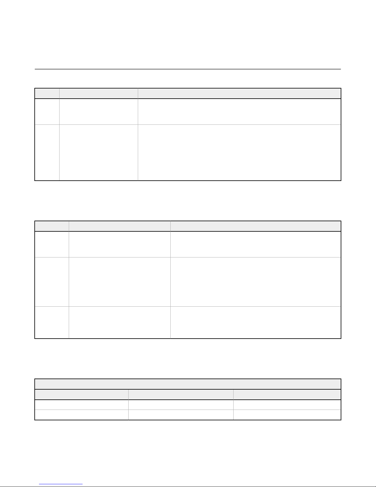
Registers Animation Description
6301, 6312, 6323, 6334, 6345
Off Indicator off
Steady Color 1 solid on at defined intensity
Flash Color 1 flashes at defined speed, intensity and pattern
Two Color Flash Color 1 and color 2 flash alternatively at defined speed, intensities and pattern
Half/Half Top/Bottom Color 1 is displayed on the top 50% of the indicator and color 2 is displayed on the bottom
50% of the indicator at defined intensities
Half/Half Left/Right Color 1 is displayed on the left 50% of the indicator and color 2 is displayed on the right 50%
of the indicator at defined intensities
Half/Half Rotate Color 1 is displayed on 50% of the indicator and color 2 is displayed on 50% of the indicator
while rotating at defined speed, intensities and rotational direction
Chase Color 1 is displayed on 25% of the indicator and color 2 is displayed on 75% of the indicator
while rotating at defined speed, intensities and rotational direction
Intensity Sweep Color 1 repeatedly increases and decreases intensity between 0% and 100% at defined
speed
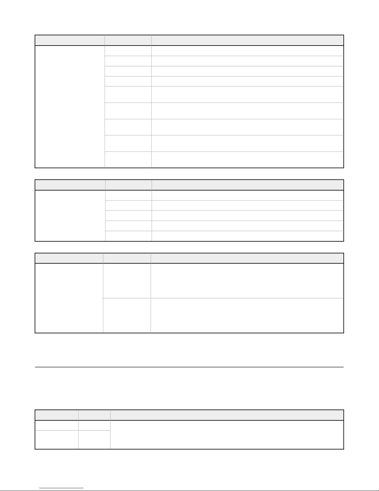
Registers Pattern Description
6307, 6318, 6329, 6340, 6351
Normal Flash with a 50% duty cycle
Strobe Strobe with an 20% duty cycle
3-Pulse Flash three times, then off, repeat
SOS Flash three times quickly, three times slowly, then three times quickly
Random Randomized pattern
Registers State Delays Description
6309, 6310, 6320, 6321, 6331,
6332, 6342, 6343, 6353, 6354
State On-delay
Defines the amount of time the device waits to move into the next visual state after activation.
State On-Delay defines the operation of the visual state while Input On-Delay (registers 6001
and 6002) defines the operation of output register change. (e.g.) If the device's job input is
active and the On-Delay is set to 1000 ms it will remain in the Job state for 1000 ms after the
sensor is triggered or the touch surface is touched.
Job state
Defines the amount of time the device will stay in the visual style of the current pick to light
state after activation before moving to the next state. (e.g.) After a successful pick from the
Job state the device will move to the Acknowledge state. If the Acknowledge state Off-Delay is
set to 3000 ms the device will remain in the Acknowledge state for 3000 ms before moving to
the next visual state. This parameter is useful to show a pick was acknowledged.
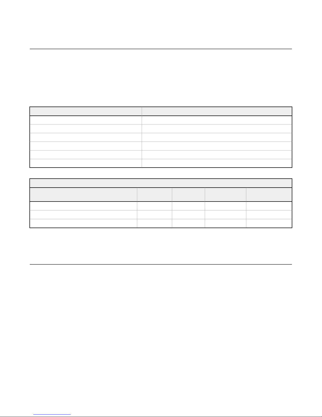
2.2 Indicator Touch Surface and Optical Sensor Operation
Each input method can be defined as primary or secondary. This allows the input methods (touch or optical sensor) to be
used combined as one or independently of each other.
Primary Input Operation—
• Input 1—Touch function
• Input 2—Optical sensor
Input Register Description
Input 1 6001 On-delay—Defines the time the button must be pushed or the sensor must be tripped to change the output from 0
to 1.
For example, if input 1 has an on-delay of 1000 ms, the touch surface must be held for 1000 ms before the output
register 7941 changes from 0 to 1.
Input 2 6003
PTL110S Pick-To-Light Devices
6 www.bannerengineering.com - Tel: + 1 888 373 6767