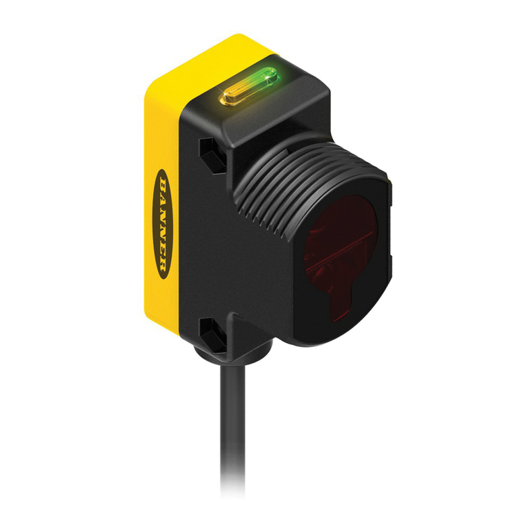
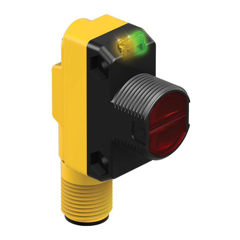
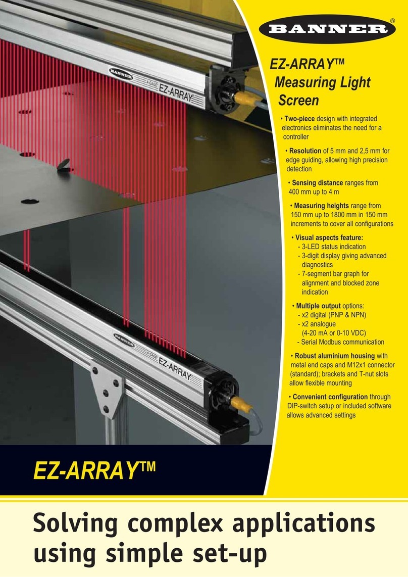
Banner Q5X User manual

Q5X Laser Triangulation Sensor with Analog Outputs and
IO-Link Instruction Manual
February 9, 2023
© Banner Engineering Corp. All rights reserved.

i
Contents
Chapter: 1 Product Description . . . . . . . . . . . . . . . . . . . . . . . . . . . . . . . . . . . . . . . . . 1
Models . . . . . . . . . . . . . . . . . . . . . . . . . . . . . . . . . . . . . . . . . . . . . . . . . 1
Overview . . . . . . . . . . . . . . . . . . . . . . . . . . . . . . . . . . . . . . . . . . . . . . . . 1
Class 2 Laser Description and Safety Information . . . . . . . . . . . . . . . . . . . . . . . . . . . 1
Features . . . . . . . . . . . . . . . . . . . . . . . . . . . . . . . . . . . . . . . . . . . . . . . . 2
Display and Indicators . . . . . . . . . . . . . . . . . . . . . . . . . . . . . . . . . . . . . . 2
Buttons . . . . . . . . . . . . . . . . . . . . . . . . . . . . . . . . . . . . . . . . . . . . . . 3
Chapter: 2 Installation . . . . . . . . . . . . . . . . . . . . . . . . . . . . . . . . . . . . . . . . . . . . . . . 4
Sensor Orientation . . . . . . . . . . . . . . . . . . . . . . . . . . . . . . . . . . . . . . . . . . . 4
Mount the Device . . . . . . . . . . . . . . . . . . . . . . . . . . . . . . . . . . . . . . . . . . . . 4
Wiring Diagrams . . . . . . . . . . . . . . . . . . . . . . . . . . . . . . . . . . . . . . . . . . . . 5
Cleaning and Maintenance . . . . . . . . . . . . . . . . . . . . . . . . . . . . . . . . . . . . . . . 5
Button Map from RSD1 to Sensor . . . . . . . . . . . . . . . . . . . . . . . . . . . . . . . . . . . 5
Chapter: 3 Sensor Programming . . . . . . . . . . . . . . . . . . . . . . . . . . . . . . . . . . . . . . . . . 6
Channel 1 and Channel 2 (CH1/CH2) . . . . . . . . . . . . . . . . . . . . . . . . . . . . . . . . . 6
Setup Mode . . . . . . . . . . . . . . . . . . . . . . . . . . . . . . . . . . . . . . . . . . . . . . 6
TEACH Procedures (Analog) . . . . . . . . . . . . . . . . . . . . . . . . . . . . . . . . . . . 9
Two-Point (2-Pt) TEACH (Channel 1 Only) . . . . . . . . . . . . . . . . . . . . . . . . . . . . . . . . . . . . . 9
One-Point (1-PT) TEACH (Channel 1 Only) . . . . . . . . . . . . . . . . . . . . . . . . . . . . . . . . . . . 10
TEACH (tch2) Mode (Discrete) . . . . . . . . . . . . . . . . . . . . . . . . . . . . . . . . . 11
Two-Point Static Background Suppression (2-Pt) (Channel 2 Only) . . . . . . . . . . . . . . . . . 11
Dynamic Background Suppression (dYn) (Channel 2 Only) . . . . . . . . . . . . . . . . . . . . . . . 12
One-Point Window (FGS) (Foreground Suppression) (Channel 2 Only) . . . . . . . . . . . . . 13
One-Point Background Suppression (bGS) (Channel 2 Only) . . . . . . . . . . . . . . . . . . . . . 15
Dual (Intensity + Distance) (duAL) (Channel 2 Only) . . . . . . . . . . . . . . . . . . . . . . . . . . . . 16
Loss of Signal (LOS) . . . . . . . . . . . . . . . . . . . . . . . . . . . . . . . . . . . . . . 17
Input Wire Function (inPt) . . . . . . . . . . . . . . . . . . . . . . . . . . . . . . . . . . . . 17
Trigger (trG) . . . . . . . . . . . . . . . . . . . . . . . . . . . . . . . . . . . . . . . . . . . 17
Slope (SLPE) . . . . . . . . . . . . . . . . . . . . . . . . . . . . . . . . . . . . . . . . . . 18
Output (out2) . . . . . . . . . . . . . . . . . . . . . . . . . . . . . . . . . . . . . . . . . . 19
Adaptive Tracking (trc2) . . . . . . . . . . . . . . . . . . . . . . . . . . . . . . . . . . . . 19
Window Size (und2) . . . . . . . . . . . . . . . . . . . . . . . . . . . . . . . . . . . . . . 20
Base Measurement Rate (SPd) . . . . . . . . . . . . . . . . . . . . . . . . . . . . . . . . . 20
Averaging . . . . . . . . . . . . . . . . . . . . . . . . . . . . . . . . . . . . . . . . . . . . 20
Output Timing Delays (dLY2) . . . . . . . . . . . . . . . . . . . . . . . . . . . . . . . . . . 21
Delay Timers . . . . . . . . . . . . . . . . . . . . . . . . . . . . . . . . . . . . . . . . . . . . . . . . . . . . . . . . . . . 22
Totalizer (totL) . . . . . . . . . . . . . . . . . . . . . . . . . . . . . . . . . . . . . . . . . . . . . . . . . . . . . . . . . . 22
Hysteresis (hYS2) . . . . . . . . . . . . . . . . . . . . . . . . . . . . . . . . . . . . . . . . 22
Zero Reference Location (ZEro) . . . . . . . . . . . . . . . . . . . . . . . . . . . . . . . . 23
Shift the Zero Reference Location after a TEACH (ShFt) . . . . . . . . . . . . . . . . . . . 23
Offset (oFS1 or oFS2) . . . . . . . . . . . . . . . . . . . . . . . . . . . . . . . . . . . . . 24
Display View (diSP) . . . . . . . . . . . . . . . . . . . . . . . . . . . . . . . . . . . . . . . 25
Units (unIt) . . . . . . . . . . . . . . . . . . . . . . . . . . . . . . . . . . . . . . . . . . . 25
Output Type Polarity (PoL) . . . . . . . . . . . . . . . . . . . . . . . . . . . . . . . . . . . 25
Exit Setup Mode (End) . . . . . . . . . . . . . . . . . . . . . . . . . . . . . . . . . . . . . 25
Reset to Factory Defaults (rSEt) . . . . . . . . . . . . . . . . . . . . . . . . . . . . . . . . 25
Factory Default Settings . . . . . . . . . . . . . . . . . . . . . . . . . . . . . . . . . . . . . . . . . . . . . . . . . . 25
Manual Adjustments . . . . . . . . . . . . . . . . . . . . . . . . . . . . . . . . . . . . . . . . . 26
Remote Input . . . . . . . . . . . . . . . . . . . . . . . . . . . . . . . . . . . . . . . . . . . . . 26
Select the TEACH Mode Using the Remote Input . . . . . . . . . . . . . . . . . . . . . . . 27
Reset to Factory Defaults Using the Remote Input . . . . . . . . . . . . . . . . . . . . . . . 27
Locking and Unlocking the Sensor Buttons . . . . . . . . . . . . . . . . . . . . . . . . . . . . . 27
Button Instructions . . . . . . . . . . . . . . . . . . . . . . . . . . . . . . . . . . . . . . 27
ii
Remote Input Instructions . . . . . . . . . . . . . . . . . . . . . . . . . . . . . . . . . . 28
Sync Master/Slave . . . . . . . . . . . . . . . . . . . . . . . . . . . . . . . . . . . . . . . . . . 28
Chapter: 4 IO-Link Interface . . . . . . . . . . . . . . . . . . . . . . . . . . . . . . . . . . . . . . . . . . 29
Chapter: 5 Q5X Analog Specifications . . . . . . . . . . . . . . . . . . . . . . . . . . . . . . . . . . . . . 30
Dimensions . . . . . . . . . . . . . . . . . . . . . . . . . . . . . . . . . . . . . . . . . . . . . . 32
Typical Performance Curves . . . . . . . . . . . . . . . . . . . . . . . . . . . . . . . . . . . . . 32
Chapter: 6 Additional Information . . . . . . . . . . . . . . . . . . . . . . . . . . . . . . . . . . . . . . . 34
Dual (Intensity + Distance) Mode . . . . . . . . . . . . . . . . . . . . . . . . . . . . . . . . . . 34
Dual Mode Reference Surface Considerations . . . . . . . . . . . . . . . . . . . . . . . . . . . 34
Dual Mode Considerations for Clear and Transparent Object Detection . . . . . . . . . . . . . . 35
Abbreviations . . . . . . . . . . . . . . . . . . . . . . . . . . . . . . . . . . . . . . . . . . . . . 36
Chapter: 7 Accessories . . . . . . . . . . . . . . . . . . . . . . . . . . . . . . . . . . . . . . . . . . . . . 40
Cordsets . . . . . . . . . . . . . . . . . . . . . . . . . . . . . . . . . . . . . . . . . . . . . . . 40
Brackets . . . . . . . . . . . . . . . . . . . . . . . . . . . . . . . . . . . . . . . . . . . . . . . 40
Reference Targets . . . . . . . . . . . . . . . . . . . . . . . . . . . . . . . . . . . . . . . . . . 42
RSD1 Remote Display . . . . . . . . . . . . . . . . . . . . . . . . . . . . . . . . . . . . . . . . 42
Chapter: 8 Product Support and Maintenance . . . . . . . . . . . . . . . . . . . . . . . . . . . . . . . . 43
Troubleshooting . . . . . . . . . . . . . . . . . . . . . . . . . . . . . . . . . . . . . . . . . . . 43
Contact Us . . . . . . . . . . . . . . . . . . . . . . . . . . . . . . . . . . . . . . . . . . . . . . 43
FCC Part 15 Class A . . . . . . . . . . . . . . . . . . . . . . . . . . . . . . . . . . . . . . . . . 43
Industry Canada Class A . . . . . . . . . . . . . . . . . . . . . . . . . . . . . . . . . . . . . . . 43
Banner Engineering Corp Limited Warranty . . . . . . . . . . . . . . . . . . . . . . . . . . . . . 43
. . . . . . . . . . . . . . . . . . . . . . . . . . . . . . . . . . . . . . . . . . . . . . . . . . . . 44

1 © Banner Engineering Corp. www.bannerengineering.com
PRODUCT DESCRIPTION
1. Product Description
Laser sensor with an analog output and IO-Link
WARNING
!
DO NOT USE THIS DEVICE FOR PERSONNEL PROTECTION
Using this device for personnel protection could result in serious injury or death.
• This device does not include the self-checking redundant circuitry necessary to allow its use in personnel
safety applications. A device failure or malfunction can cause either an energized (on) or de-energized (off)
output condition.
1.1. Models
1.2. Overview
The Q5X Laser Triangulation Sensor offers analog and discrete (switched) outputs with IO-Link.
The normal sensor state is Run mode. From Run mode, users may change the switch point value and channel selection and perform the selected
TEACH method.
The secondary sensor state is Setup mode. From Setup mode, users may select the TEACH mode, adjust all standard operating parameters,
and perform a factory reset.
1.3. Class 2 Laser Description and Safety Information
CAUTION
!
RETURN DEFECTIVE UNITS TO THE MANUFACTURER.
Use of controls or adjustments or performance of procedures other than those specified herein may result in haz-
ardous radiation exposure.
• Do not attempt to disassemble this sensor for repair. A defective unit must be returned to the manufacturer.
• Laser measurement sensor with a range up to 3000 mm
• Bright output indicators and real-time distance feedback provide easy set up and trouble-
shooting for reduced installation costs
• Exceptionally high excess gain enables the sensor to reliably detect the darkest objects
(< 6% reflective black targets), including black targets against a black background, black
targets against a shiny metal background, clear and reflective objects, multicolor pack-
aging, and targets of all colors
• Dual independent output channels and communication over IO-Link
• Optional Remote Sensor Display (RSD) (available separately) enables remote program-
ming and monitoring
Model Sensing Range Channel 1 Default Channel 2 Default Connection
Q5XKULAF3000-Q8 95 mm to 3000 mm Analog voltage output (0-10V) Push/pull discrete output or
IO-Link
270° rotatable integral 5-pin M12
male quick disconnect fitting
Q5XKILAF3000-Q8 Analog current output (4-20mA)

© Banner Engineering Corp. www.bannerengineering.com 2
PRODUCT DESCRIPTION
CAUTION
!
NEVER STARE DIRECTLY INTO THE SENSOR LENS.
Laser light can damage your eyes.
• Avoid placing any mirror-like object in the beam. Never use a mirror as a retroreflective target.
Class 2 lasers are lasers that emit visible radiation in the wavelength range from 400 nm to 700 nm, where eye protection is normally afforded
by aversion responses, including the blink reflex. This reaction may be expected to provide adequate protection under reasonably foreseeable
conditions of operation, including the use of optical instruments for intrabeam viewing.
Low-power lasers are, by definition, incapable of causing eye injury within the duration of a blink (aversion response) of 0.25 seconds. They also
must emit only visible wavelengths (400 to 700 nm). Therefore, an ocular hazard may exist only if individuals overcome their natural aversion to
bright light and stare directly into the laser beam.
1.4. Features
The Q5X has three major features.
1.4.1. Display and Indicators
The display is a four-digit, seven-segment LED. Run mode is the primary view displayed.
For Safe Laser Use - Class 2 Lasers
• Do not stare at the laser.
• Do not point the laser at a person’s eye.
• Mount open laser beam paths either above or below eye level, where practical.
• Terminate the beam emitted by the laser product at the end of its useful path.
Class 2 Red Laser models: Reference IEC 60825-1:2014
Figure 1: FDA (CDRH) warning label (Class 2)
Output: < 1.0 mW
Laser wavelength: 640 to 670 nm
Pulse Duration: 20 µs to 2 ms
Figure 2: Q5X Features
1) Two output indicators (amber)
2) Display
3) Buttons
LASER LIGHT
DO NOT STARE INTO BEAM
CLASS 2 LASER PRODUCT
IEC 60825-1:2014. Wavelength
640-670nm; 1.0mW max. Complies with
21 CFR 1040.10 and 1040.11 except for
conformance with IEC 60825-1: 2014
as described in Laser Notice
No. 56, dated May 8, 2019.
1
23

3 © Banner Engineering Corp. www.bannerengineering.com
PRODUCT DESCRIPTION
For 1-PT, 2-PT, BGS, FGS, and DYN TEACH modes, the display shows the current distance to the target in centimeters. For Dual TEACH mode,
the display shows the percentage matched to the taught reference surface. A display value of 999P indicates the sensor has not been taught.
1.4.2. Buttons
Use the sensor buttons (SELECT)(TEACH), (+)(CH1/CH2), and (-)(MODE) to program the sensor.
Figure 4: Q5X sensor face
Figure 3: Display in Run Mode
1) Stability Indicator (STB—Green)
2) Active TEACH Indicators
◦ 2-PT - Two-Point TEACH (Amber)
◦ 1-PT - One-Point TEACH (Amber)
3) Display value indicator (MM - Amber)
Output Indicators
• Ch1: On when the displayed distance is within the taught
analog output window
• Ch2: On when the displayed distance is within the taught
discrete output window
Stability Indicator (STB)
• On—Stable signal within the specified sensing range
• Flashing—Marginal signal, the target is outside the limits of
the specified sensing range, or a multiple peak condition
exists
• Off—No target detected within the specified sensing range
Active TEACH Indicators (2PT and 1PT)
• 2-PT on—Two-point TECH mode selected (default)
• 1-PT on—One-point TEACH mode selected
Display Value Indicator (MM)
• On—Display shows the distance in millimeters (default)
• Off—Display shows the analog output value
• Toggle off the MM light by pressing SELECT when the
sensor is in run mode. This changes the display to show the
analog output value. Press SELECT again to show the
distance value.
(SELECT)(TEACH)
• Press to select menu items in Setup mode
• Press and hold for longer than 2 seconds to start the
currently selected TEACH mode (the default is two-point
TEACH)
(+)(CH1/CH2)
• Press to navigate the sensor menu in Setup mode
• Press to change setting values; press and hold to increase
numeric values
• Press and hold for longer than 2 seconds to switch between
Channel 1 and Channel 2
(-)(MODE)
• Press to navigate the sensor menu in Setup mode
• Press to change setting values; press and hold to decrease
numeric values
• Press and hold for longer than 2 seconds to enter Setup
mode
NOTE: When navigating the menu, the menu items loop.
STB 2-PT 1-PT MM
12

© Banner Engineering Corp. www.bannerengineering.com 4
INSTALLATION
2. Installation
2.1. Sensor Orientation
Optimize detection reliability and minimum object separation performance with correct sensor-to-target orientation. To ensure reliable detection,
orient the sensor as shown in relation to the target to be detected.
Figure 1: Optimal Orientation of Target to Sensor
See the following figures for examples of correct and incorrect sensor-to-target orientation as certain placements may pose problems for sensing
some targets. The Q5X can be used in the less preferred orientation and at steep angles of incidence and still provide reliable detection perfor-
mance due to its high excess gain. For the minimum object separation distance required for each case, refer to Typical Performance Curves on
page 32.
2.2. Mount the Device
1. If a bracket is needed, mount the device onto the bracket.
2. Mount the device (or the device and the bracket) to the machine or equipment at the desired location. Do not tighten the mounting
screws at this time.
3. Check the device alignment.
4. Tighten the mounting screws to secure the device (or the device and the bracket) in the aligned position.
Figure 2: Orientation by a wall Figure 3: Orientation for a moving object Figure 4: Orientation for a height difference
Figure 5: Orientation for a color or luster
difference
Figure 6: Orientation for highly reflective
target1
1. Applying tilt to sensor may improve performance on reflective targets. The direction and magnitude of the tilt depends on the application, but a 15° tilt is often
sufficient.
Incorrect
Correct
CC
CC
Incorrect
Correct
CC
IncorrectCorrect
Horizontal
Orientation
Vertical
Orientation
(Optimal)
CC
Reflective
Surface
(optional)

5 © Banner Engineering Corp. www.bannerengineering.com
INSTALLATION
2.3. Wiring Diagrams
2.4. Cleaning and Maintenance
Clean the sensor when soiled and use with care.
Handle the sensor with care during installation and operation. Sensor windows soiled by fingerprints, dust, water, oil, etc. may create stray light
that may degrade the peak performance of the sensor. Blow the window clear using filtered, compressed air, then clean as necessary using only
water and a lint-free cloth.
2.5. Button Map from RSD1 to Sensor
The sensor may be optionally connected to the Banner RSD1 remote display accessory. Refer to this table for the RSD1 button association with
your sensor.
Figure 7: Wiring diagram for 4-20mA Analog Figure 8: Wiring diagram for 0-10V Analog
Table 1:Button association between the RSD1 and the Q4X/Q5X sensors
Device Up Button Down Button Enter Button Escape Button
RSD1
Q4X and Q5X N/A
shield
+
12–30 V DC
D_Out/IO-Link
A_Out
Input
–
Load
* Push-Pull output. User-configurable PNP/NPN setting.
4-20 mA
bu (3)
bn (1)
wh (2)
bk (4)
gy (5)
**
PNP
NPN
shield
+
12–30 V DC
D_Out/IO-Link
A_Out
Input
–
Load
* Push-Pull output. User-configurable PNP/NPN setting.
0-10 V
bu (3)
bn (1)
wh (2)
bk (4)
gy (5)
**
PNP
NPN
1
4
5
3
2

© Banner Engineering Corp. www.bannerengineering.com 6
SENSOR PROGRAMMING
3. Sensor Programming
Program the sensor using the buttons on the sensor or the remote input (limited programming options).
In addition to programming the sensor, use the remote input to disable the buttons for security, preventing unauthorized or accidental program-
ming changes. See Locking and Unlocking the Sensor Buttons on page 27 for more information.
3.1. Channel 1 and Channel 2 (CH1/CH2)
Press CH1/CH2 button to switch between Channel 1 and Channel 2.
Within each channel, there are options specific to that channel. For settings that are common to both channels, the menus are only available in
Channel 1. The default is Channel 1.
To switch between Channel 1 and Channel 2:
1) Press and hold CH1/CH2 for longer than 2 seconds. The current selection displays.
2) Press CH1/CH2 again. The new selection flashes slowly.
3) Press SELECT to change the Channel and return to Run mode.
If neither SELECT nor CH1/CH2 are pressed after step 2, the new selection flashes slowly for a few seconds, then flashes quickly and the sensor
automatically changes the Channel and returns to Run mode.
3.2. Setup Mode
Access Setup mode and the sensor menu from Run mode by pressing and holding MODE for longer than 2 seconds. Use + and - to navigate
through the menu. Press SELECT to select a menu option and access the submenus. Use + and - to navigate through the submenus. Press
SELECT to select a submenu option and return to the top menu, or press and hold SELECT for longer than 2 seconds to select a submenu option
and return immediately to Run mode.
To exit Setup mode and return to Run mode, navigate to End and press SELECT.
The number that follows a menu option, for example tch1, indicates the channel that is selected. For menu items without a number (excluding
submenu items), these menu options are only available from Channel 1 and the settings apply to both channels.

7 © Banner Engineering Corp. www.bannerengineering.com
SENSOR PROGRAMMING
Figure 1: Sensor Menu Map—Channel 1

© Banner Engineering Corp. www.bannerengineering.com 8
SENSOR PROGRAMMING
Figure 2: Sensor Menu Map—Channel 2

9 © Banner Engineering Corp. www.bannerengineering.com
SENSOR PROGRAMMING
3.2.1. TEACH Procedures (Analog)
Use the following procedures to teach the Ch1 analog output.
To cancel a TEACH procedure, press TEACH for longer than 2 seconds, or hold the remote input low for longer than 2 seconds. CnCL momen-
tarily displays when a TEACH procedure is canceled.
3.2.1.1. Two-Point (2-Pt) TEACH (Channel 1 Only)
Two-point TEACH sets the distance values associated with 0 V and 10 V (4 mA and 20 mA) based on taught target distances.
Figure 3: Two-Point TEACH
The sensor must be set to tch = 2-Pt to use the following instructions. To program the sensor using remote input, remote input must be enabled
(inPt = SEt).
1) Present the target at the desired 0 V (4 mA) distance.
2) Start the TEACH mode.
3) Teach the sensor at the 0 V (4 mA) distance.
4) Present the target at the desired 10 V (20 mA) distance.
5) Teach the sensor at the 10 V (20 mA) distance.
Method Action Result
Push Button Present the first target. The sensor-to-target distance must be within the sensor's
range. The target's measurement value displays.
Remote Input
Method Action Result
Push Button Press and hold TEACH for longer than 2 seconds.
SEt and O U flash alternately on the display.
The 2-Pt indicator flashes.
Remote Input Single-pulse the remote input.
Method Action Result
Push Button Press TEACH to teach the target. The measurement value flashes briefly, and
the sensor is taught the first target. SEt and 10
U flash alternately on the display. The 2-Pt
indicator flashes.
Remote Input Single-pulse the remote input.
Method Action Result
Push Button Present the second target. The sensor-to-target distance must be within the sensor's
range.
SEt and 10 U flash alternately on the display.
The 2-Pt indicator flashes.
Remote Input
10 V
0 V
2
Press and Hold
> 2s
Press again
4
Teach 0 V
Teach 10 V
1
Press again
35
T
T

© Banner Engineering Corp. www.bannerengineering.com 10
SENSOR PROGRAMMING
If the same target is taught both times, Lo and SPAn flash alternately on the display, the 10 V (20 mA) value is automatically adjusted to maintain
the minimum window size, the new distance quickly flashes four times, and the sensor returns to Run mode.
It is possible to skip teaching the 0 V (4mA) and/or the 10 V (20mA) point and continue to use the existing setting. At the applicable teach step,
when using the push button, hold - for four seconds. The sensor displays SAVE and then flashes the existing value. When using the remote
input, double-pulse the remote input.
3.2.1.2. One-Point (1-PT) TEACH (Channel 1 Only)
One-point TEACH mode defines the span of the analog output. One-point TEACH also defines the 5 V (12 mA) midpoint of the analog output to
center the analog output around a reference target position.
Figure 4: One-Point Window
The sensor must be set to tch = 1-Pt to use the following instructions. To program the sensor using remote input, remote input must be enabled
(inPt = SEt).
1) Present the target at the desired 5 V (12 mA) distance.
2) Start the TEACH mode.
3) Teach the sensor the 5 V (12 mA) midpoint.
Method Action Result
Push Button Press TEACH to teach the target.
The new switch point flashes rapidly and the
sensor returns to Run mode.
Remote Input Single-pulse the remote input.
Method Action Result
Push Button Present the first target. The sensor-to-target distance must be within the sensor's
range. The target's measurement value displays.
Remote Input
Method Action Result
Push Button Press and hold TEACH for longer than 2 seconds. SEt and 5 U flash alternately on the display.
The 1-Pt indicator flashes.
Remote Input No action is required. N/A
Method Action Result
Push Button Press TEACH to teach the target.
The measurement value flashes briefly, and
the sensor returns to Run mode.
Remote Input Single-pulse the remote input.
T
10 V
0 V
Press and Hold
> 2s
Teach 5 V 5 V 5 V
10 V
0 V
5 V
1
Press again
23
T

11 © Banner Engineering Corp. www.bannerengineering.com
SENSOR PROGRAMMING
3.2.2. TEACH (tch2) Mode (Discrete)
Use this menu to select the TEACH mode. The default is two-point TEACH. Channel 2 is discrete only.
The number that follows tch on the display indicates which channel is selected.
•2-Pt—Two-point static TEACH
•dYn—Dynamic background suppression
•FGS—One-point window (foreground suppression)
•bGS—One-point background suppression
•duAL—Dual (intensity + distance) window
After the TEACH mode is selected, from Run mode, press and hold TEACH for longer than 2 seconds to start the TEACH mode and program
the sensor.
3.2.2.1. Two-Point Static Background Suppression (2-Pt) (Channel 2 Only)
Two-point TEACH sets a single switch point. The sensor sets the switch point between two taught target distances, relative to the shifted origin
location.
Figure 5: Two-Point Static Background Suppression (Light Operate shown)
The sensor must be set to tch = 2-Pt to use the following instructions. To program the sensor using remote input, remote input must be enabled
(inPt = SEt).
1) Present the target.
2) Start the TEACH mode.
3) Teach the sensor.
4) Present the target.
Method Action Result
Push Button Present the first target. The sensor-to-target distance must be within the sensor's
range. The target's measurement value displays.
Remote Input
Method Action Result
Push Button Press and hold TEACH for longer than 2 seconds. SEt and 1St flash alternately on the display.
The 1-Pt and 2-Pt indicators flash.
Remote Input No action is required. N/A
Method Action Result
Push Button Press TEACH to teach the target. The sensor is taught the first target. SEt, 2nd,
and the current distance measurement flash
alternately on the display. The 1-Pt and 2-Pt
indicators flash.
Remote Input Single-pulse the remote input.
1
Switch
Point
Value
4
2
Press and
Hold > 2s Press
again
3
Press
again
5
T

© Banner Engineering Corp. www.bannerengineering.com 12
SENSOR PROGRAMMING
5) Teach the sensor.
See Typical Performance Curves on page 32 for the minimum object separation.
3.2.2.2. Dynamic Background Suppression (dYn) (Channel 2 Only)
Dynamic TEACH sets a single switch point during machine run conditions. Dynamic TEACH is recommended for applications where a machine
or process may not be stopped for teaching. The sensor takes multiple samples and the switch point is set between the minimum and the
maximum sampled distances.
Figure 6: Dynamic Background Suppression
The sensor must be set to tch = dYn to use the following instructions. The DYN indicator is amber to indicate Dynamic TEACH mode. To program
the sensor using remote input, remote input must be enabled (out2 = SEt).
1) Present the target.
Method Action Result
Push Button Present the second target. The sensor-to-target distance must be within the sensor's
range.
SEt, 2nd, and the distance measurement
flash alternately on the display. The 1-Pt and
2-Pt indicators flash.
Remote Input
Method Action Result
Push Button Press TEACH to teach the target.
The new switch point flashes rapidly and the
sensor returns to Run mode.
Remote Input Single-pulse the remote input.
Table 1:Expected TEACH Behavior for Two-Point Static Background Suppression
Condition TEACH Result Display
Two valid distances that are greater than or
equal to the horizontal minimum object
separation
Sets a switch point between the two taught distances. The switch point distance flashes on the
display.
Two valid distances that are less than the
horizontal minimum object separation
Sets a switch point in front of the furthest taught distance
equal to the uniform reflectivity minimum object
separation.
bGS and the switch point distance flash
alternately on the display.
One valid distance with one invalid TEACH
point
Sets a switch point between the one taught distance and
the maximum range.
obJt and the switch point distance flash
alternately on the display.
Two invalid TEACH points Sets a switch point for the currently selected channel at
197 cm.
FuLL and the switch point distance flash
alternately on the display.
Method Action Result
Push Button Present the first target. The sensor-to-target distance must be within the sensor's
range. The target's measurement value displays.
Remote Input
T
Switch
Point
Value
1
4
Press to start
sampling
Press to stop
sampling
2
Press and
Hold > 2s
35

13 © Banner Engineering Corp. www.bannerengineering.com
SENSOR PROGRAMMING
2) Start the TEACH mode.
3) Teach the sensor.
4) Present the targets.
5) Teach the sensor.
See Typical Performance Curves on page 32 for the minimum object separation.
3.2.2.3. One-Point Window (FGS) (Foreground Suppression) (Channel 2 Only)
One-point window sets a window (two switch points) centered around the taught target distance. Loss of signal is treated as a detection in
One-Point Window mode. The size of the taught window is the vertical minimum object separation. See Typical Performance Curves on page 32.
Manually adjust the window size from Run mode using + and -.
Method Action Result
Push Button Press and hold TEACH for longer than 2 seconds. dYn and Strt flash alternately on the display.
The 1-Pt and 2-Pt indicators flash.
Remote Input No action is required. N/A
Method Action Result
Push Button Press TEACH to teach the target. The sensor begins sampling target distance
information and dYn and StoP flash
alternately on the display. The 1-Pt and 2-Pt
indicators flash.
Remote Input Single-pulse the remote input.
Method Action Result
Push Button
Present additional targets. The sensor-to-target distance must be within the sensor's
range.
The sensor continues to sample target
distance information and dYn and StoP flash
alternately on the display. The 1-Pt and 2-Pt
indicators flash.
Remote Input
Method Action Result
Push Button Press TEACH to stop teaching the sensor.
The new switch point flashes rapidly and the
sensor returns to Run mode.
Remote Input Single-pulse the remote input.
Table 2:Expected TEACH Behavior for Dynamic Background Suppression
Condition TEACH Result Display
Two valid distances that are greater than or
equal to the horizontal minimum object
separation
Sets a switch point between the two taught distances. The switch point distance flashes on the
display.
Two valid distances that are less than the
horizontal minimum object separation
Sets a switch point in front of the furthest taught distance
equal to the uniform reflectivity minimum object
separation.
bGS and the switch point distance flash
alternately on the display.
One valid distance with one invalid TEACH
point
Sets a switch point between the one taught distance and
the maximum range.
obJt and the switch point distance flash
alternately on the display.
Two invalid TEACH points Sets a switch point for the currently selected channel at
120 cm.
bGS and the switch point distance flash
alternately on the display.
T
T

© Banner Engineering Corp. www.bannerengineering.com 14
SENSOR PROGRAMMING
Figure 7: One-Point Window (Foreground Suppression)
The sensor must be set to tch = FGS to use the following instructions. The FGS indicator is amber to indicate One-Point Window (Foreground
Suppression) mode. To program the sensor using remote input, remote input must be enabled (out2 = SEt).
1) Present the target.
2) Start the TEACH mode.
3) Teach the sensor.
See Typical Performance Curves on page 32 for the minimum object separation.
Method Action Result
Push Button Present the target. The sensor-to-target distance must be within the sensor's range. The target's measurement value displays.
Remote Input
Method Action Result
Push Button Press and hold TEACH for longer than 2 seconds.
Light Operate
SEt and on flash alternately on the display.
The 1-Pt and 2-Pt indicators flash.
Dark Operate
SEt and oFF flash alternately on the display.
The 1-Pt and 2-Pt indicators flash.
Remote Input No action required. N/A
Method Action Result
Push Button Press TEACH to teach the target.
The sensor returns to Run mode.
Remote Input Single-pulse the remote input.
Table 3:Expected TEACH Behavior for One-Point Window (Foreground Suppression)
Condition TEACH Result Display
One valid TEACH point with both switch
points in range (with offset, if applicable)
Sets a window (two switch points) centered around the
taught distance. The ± window size is equal to the
non-uniform reflectivity minimum object separation. The
two switch points always stay within the specified
sensing range.
The sensor returns to Run mode.
One invalid TEACH Point Sets a window (two switch points) centered around 150
cm. The window size is ± 10 cm.
---- and the window center point distance
flash alternately on the display.
One valid TEACH point with one switch
point within range and one switch point out
of range (with offset, if applicable)
Sets a window (two switch points) that is centered at the
TEACH point (after offset, if applicable) with one switch
point at the maximum range.
---- and the ± window size flash alternately
on the display.
One valid TEACH point that, after the
offset, results in a both switch points
outside of the range
Sets a window (two switch points) centered around 150
cm. The window size is ± 10 cm.
oFSt and the window center point distance
flash alternately on the display.
Switch
Point
Value A
Switch
Point
Value -A
1
2
Press and
Hold > 2s
Press
again
3
T

15 © Banner Engineering Corp. www.bannerengineering.com
SENSOR PROGRAMMING
3.2.2.4. One-Point Background Suppression (bGS) (Channel 2 Only)
One-point background suppression sets a single switch point in front of the taught target distance. Objects beyond the taught switch point are
ignored. The switch point is set in front of the taught target distance by the vertical minimum object separation. See Typical Performance Curves
on page 32.
Figure 8: One-Point Background Suppression
The sensor must be set to tch = bGS to use the following instructions. The BGS indicator is amber to indicate Background Suppression mode. To
program the sensor using remote input, remote input must be enabled (out2 = SEt).
1) Present the target.
2) Start the TEACH mode.
3) Teach the sensor.
Method Action Result
Push Button Present the target. The sensor-to-target distance must be within the sensor's range. The target's measurement value displays.
Remote Input
Method Action Result
Push Button Press and hold TEACH for longer than 2 seconds.
Light Operate
SEt and oFF flash alternately on the display.
The 1-Pt 2-Pt and indicators flash.
Dark Operate
SEt and on flash alternately on the display.
The1-Pt and 2-Pt indicators flash.
Remote Input No action required. N/A
Method Action Result
Push Button Press TEACH to teach the target.
The new switch point flashes rapidly and the
sensor returns to Run mode.
Remote Input Single-pulse the remote input.
Table 4:Expected TEACH Behavior for One-Point Background Suppression
Condition TEACH Result Display
One valid TEACH point
If an Offset is applied, the TEACH point is
still valid
Sets a switch point in front of the taught distance equal to
the non-uniform reflectivity minimum object separation.
The switch point distance flashes on the
display.
One invalid TEACH point Sets a switch point at 120 cm. bGS and the switch point distance flash
alternately on the display.
One valid TEACH point that, after offset,
becomes invalid Sets a switch point at 120 cm. oFSt and the switch point distance flash
alternately on the display.
Switch
Point
Value A
1
2
Press and
Hold > 2s
Press
again
3
T

© Banner Engineering Corp. www.bannerengineering.com 16
SENSOR PROGRAMMING
See Typical Performance Curves on page 32 for the minimum object separation.
3.2.2.5. Dual (Intensity + Distance) (duAL) (Channel 2 Only)
Dual (intensity + distance) TEACH records the distance and amount of light received from the reference surface. The output switches when an
object passing between the sensor and the reference surface changes the perceived distance or amount of returned light. For more information,
see Additional Information on page 34.
To use the following instructions, set the sensor to tch = duAL. The 1-Pt and 2-Pt indicators are amber.
To program the sensor using remote input, remote input must be enabled (out2 = SEt).
Figure 9: Dual TEACH (Channel 2 only)
1) Present the target.
2) Start the TEACH mode.
3) Teach the sensor.
Method Action Result
Push Button
Remote Input Present the reference target. The target's match percentage displays
Method Action Result
Push Button Press and hold the TEACH button for more than 2 seconds.
Light Operate: SEt and on flash on the
display. The 1-Pt and 2-Pt indicators flash.
Dark Operate: SEt and oFF flash on the
display. The 1-Pt and 2-Pt indicators flash.
Remote Input No action required. N/A
Method Action Result
Push Button Press the TEACH button.
The switching threshold flashes rapidly and
the sensor returns to Run mode.
Remote Input Single-pulse the remote input.
Table 5:Expected TEACH Behavior for Dual (Intensity + Distance) Mode (Sheet 1 of 2)
Condition TEACH Result Display
One valid reference surface is taught within
sensing range
Sets a dual (intensity + distance) window
centered around the taught reference surface.
The ± window size is the previously used
switching threshold, or 50% by default.
The switching threshold flashes on the display.
1
Increased
Height
and/or
Intensity
Decreased
Height
and/or
Intensity
Reference
Surface
2
Press and
Hold > 2s Press
again
3
T

17 © Banner Engineering Corp. www.bannerengineering.com
SENSOR PROGRAMMING
3.2.3. Loss of Signal (LOS)
Use this menu to select the Analog Output value used by the sensor during a loss of signal. When a signal is restored, measurement resumes.
The default is 0 V (4 mA).
The Range advanced measurement behavior is affected by the Loss of Signal option. For additional information on advanced measurements,
see Trigger (trG) on page 17. The Range advanced measurement tracks a maximum and a minimum during the measurement period, and calcu-
lates the range as follows:
Range = maximum distance – minimum distance
If the maximum and/or minimum measurements are outside of the taught range values, the Loss of Signal option determines how the range is
calculated.
3.2.4. Input Wire Function (inPt)
Use this menu to select the input wire function. The default is off, ignore all remote input pulses.
•oFF—Ignore all remote input pulses
•SEt—Remote TEACH input
•LoFF—Laser off when pulled low
•Lon—Laser on when pulled low
•nASt—Master sync line output for two-sensor cross-talk avoidance
•SLUE—Slave sync line input for two-sensor cross-talk avoidance
•trG—Trigger mode for advanced measurements (see Trigger (trG) on page 17)
To configure sensors for master-slave operation, see Sync Master/Slave on page 28.
3.2.5. Trigger (trG)
The Trigger option sets the advanced measurement that is calculated when a trigger event is detected on the remote input.
The analog output updates with the new advanced measurement on each trigger event. To use these Trigger options, the sensor Input Type
option must be set to trG.
One reference surface is taught outside the
sensing range
Sets a dual (intensity + distance) window
centered around the taught reference surface
that is outside the sensing range. The sensing
conditions may not be as reliable.
out flashes on the display.
One invalid TEACH Point No reference surface is taught, the output will
change when any object is detected.
FuLL flashes on the display.
Table 6:Analog output value during a loss of signal
Option Description
0 V (4 mA)—default The Analog Output switches to this value 2 seconds after a loss of signal. When advanced measurements are
enabled, the Analog Output is updated to this value immediately upon the release of the trigger input.
10.5 V (20.5 mA) The Analog Output switches to this value 2 seconds after a loss of signal. When advanced measurements are
enabled, the Analog Output is updated to this value immediately upon the release of the trigger input.
Hold The Analog Output holds the last value indefinitely during a loss of signal. When advanced measurements are
enabled, the last value is held across the triggered measurement periods.
Table 7:Sensor behavior in range mode
Option Description
0 V (4 mA) If the maximum or minimum measurement is outside of the taught range values, the sensor outputs 0 V (4 mA) to
indicate an out-of-range measurement.
10.5 V (20.5 mA) If the maximum or minimum measurement is outside of the taught range values, the sensor outputs 10.5 V (20.5
mA) to indicate an out-of-range measurement.
Hold The sensor limits the maximum and minimum measurements so that they cannot exceed the taught range
values.
Table 5:Expected TEACH Behavior for Dual (Intensity + Distance) Mode (Continued) (Sheet 2 of 2)
Condition TEACH Result Display
Other manuals for Q5X
12
This manual suits for next models
2
Table of contents
Other Banner Stud Sensor manuals

Banner
Banner Mini-Beam ac-Voltage Series User manual

Banner
Banner R-Gage QT50R User manual

Banner
Banner Photoelectric Sensor QS18 User manual

Banner
Banner Measuring Light Screen EZ-ARRAY User manual

Banner
Banner QS30H20 User manual

Banner
Banner Miniature Sensor Q12 User manual

Banner
Banner Plastic Fibre Optic Sensor FI22FP User manual

Banner
Banner World-Beam QS30 Owner's manual