IKA MATRIX ORBITAL DELTA PLUS User manual

IKA MATRIX ORBITAL DELTA PLUS

2 3
ENGLISH

4 5
Installation�������������������������������������������������������������������������������������������������13
EU Declaration of conformity �����������������������������������������������������������������������6
Explication of warning symbols ��������������������������������������������������������������������6
!
Safety instructions���������������������������������������������������������������������������������������� 7
Unpacking ������������������������������������������������������������������������������������������������� 10
Operation ��������������������������������������������������������������������������������������������������17
Intended use������������������������������������������������������������������������������������������������ 9
Technical Data �������������������������������������������������������������������������������������������38
Interfaces and outputs �������������������������������������������������������������������������������31
Warranty ���������������������������������������������������������������������������������������������������39
Maintenance and cleaning������������������������������������������������������������������������� 37
Accessories ������������������������������������������������������������������������������������������������37
Operator panel and display ������������������������������������������������������������������������11
Error codes ������������������������������������������������������������������������������������������������35
Menu navigation and structure ������������������������������������������������������������������ 25
!
!
!
!
!
!
Fig. 2
!
!
!
!
!
Fig. 1

6 7
Source language: German
EU Declaration of conformity
We declare under our sole responsibility that this product corresponds to the directives
2014/35/EU, 2006/42/EC, 2014/30/EU and 2011/65/EU and conforms with the following
standards or normative documents: EN 61010-1, EN 61010-2-010, EN 61010-2-051,
EN 61326-1, EN 60529 and EN ISO 12100�
A copy of the complete EU Declaration of conformity can be requested at sales@ika�com�
!
Explication of warning symbols
/// Warning symbols
Indicates an (extremely) hazardous situation, which, if not avoided, will
result in death, serious injury�
Danger!
Indicates a hazardous situation, which, if not avoided,
can result in
death, serious injury�
Warning!
Indicates a potentially hazardous situation, which, if not avoided, can
result in injury�
Caution!
!
Indicates practices which, if not avoided, can result in equipment damage�
Notice!
Indicates a hazardous situation that cause from a hot surface!
Caution!
/// General Symbols
Position number
A–––
Correct / Result!
Shows the correct execution or the result of an action step�
Wrong!
Shows the incorrect execution of an action step�
Note!
Displays action steps that require particular attention to detail�
Safety instructions
/// General information
›
Read the operating instructions completely before starting up and follow the safety
instructions.
› Keep the operating instructions in a place where it can be accessed by everyone�
› Ensure that only trained staff work with the device�
› Follow the safety instructions, guidelines, occupational health and safety and accident
prevention regulations�
›
The device must only be used in a technically perfect condition�
Caution!
› Wear your personal protective equipment in accordance with the hazard category of the
medium to be processed, there is a risk of:
- splashing of liquids
- release of toxic or combustible gases
- body parts, hair, clothing and jewellery getting caught�
!Notice!
› Pay attention to the marked sites in Fig� 1 and Fig� 2�
/// Device setup
Caution!
› The power switch of the device must be accessed immediately, directly and without risk at
any time� If access to the power switch cannot be ensured, an additional emergency stop
switch that can be easily accessed must be installed in the work area�
› Ensure that your hands / fingers do not get crushed when setting down the device�
!Notice!
› Set up the device in a spacious area on an even, stable, clean, non-slip, dry and fireproof surface�
› Make sure that the ventilation slots are not blocked at back of the device�
› Observe the minimum distances:
- between devices min� 100 mm�
- between device and wall min� 100 mm�
Min. 100 mm Min. 100 mm
Min. 100 mm
Closed lock!
Indicates the status of “locked”�
Open lock!
Indicates the status of “Unlocked”�
Indicates crushing risk to fingers / hands�
Caution!

8 9
Intended use
///
Use
The MATRIX ORBITAL DELTA PLUS device is used for mixing / tempering liquids in closed
tubes and closed plates in the preparation of samples�
Intended use: Tabletop device
/// Working with the device
Danger!
› Do not use the device in explosive atmospheres, it is not EX-protected�
› With substances capable of forming an explosive mixture, appropriate safety measures
must be applied, e�g� working under a fume hood�
› To avoid body injury and property damage, observe the relevant safety and accident
prevention measures when processing hazardous materials�
Warning!
› Only process samples that will not react dangerously to the extra energy produced through
processing� This also applies to any extra energy produced in other ways, e�g� through light
irradiation�
› Only media whose flash point lies above 170 ºC can be heated with this device (according
to EN 61010-2-010)�
› When handling hazardous substances or mixtures of substances which are toxic or
are contaminated with pathogenic micro-organisms, the user should take appropriate
precautions� Observe the national regulations, the biosafety level of your laboratory, the
material safety data sheets�
›For germs or biological material or risk goup II or higher, please observe the “Laboratory
Biosafety Manual” issued by the World Heath Organisation)�
Caution!
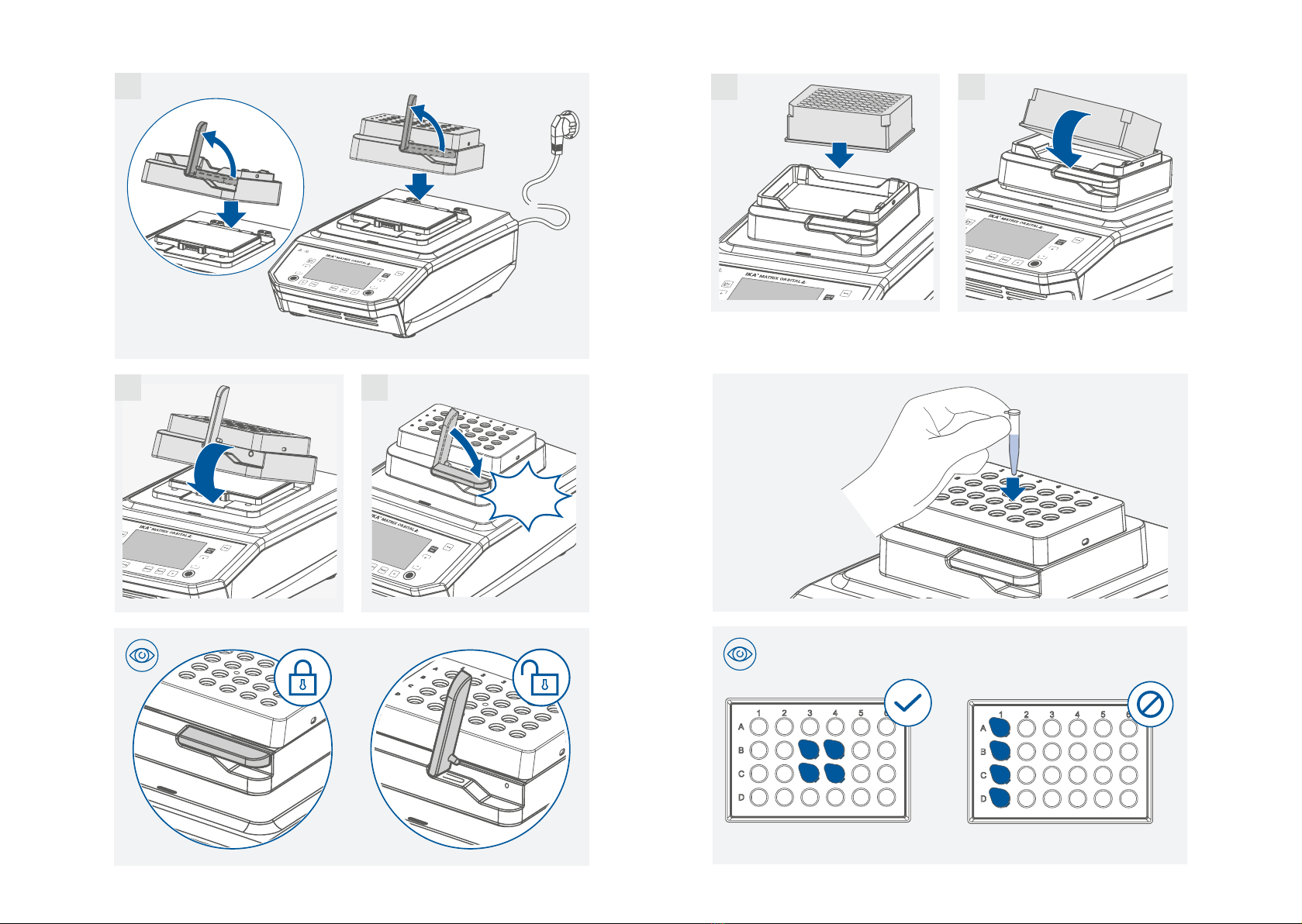
› Please pay attention to avoiding hand injury when operate the device�
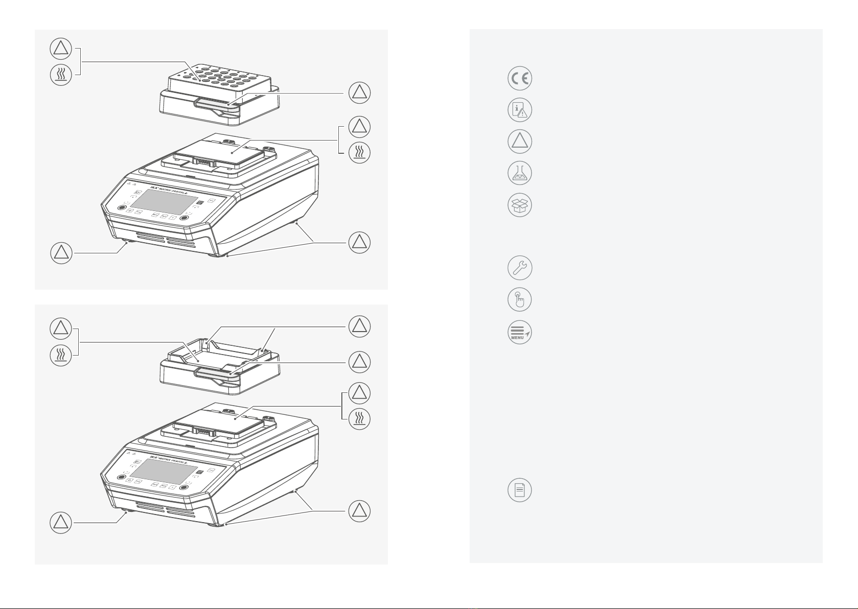
› The heating plate and the attachments can be very hot and cause injuries� Be careful when
touching the attachments�
› Pay attention to the residual heat after switching off the device�
› Allow the attachments to cool down completely before removing them�
!Notice!
› The device must be operated on flat surface and must not be moved during operation�
› Covers or parts that can be removed from the device without tools must later be refitted to
ensure safe operation� This will prevent the infiltration of foreign objects, liquids and other
contaminants�
› Never use tubes made of glass or other fragile material� Glass tubes can be smash�
› Only use sealed micro test tube and sealed microplate / deepwell plate�
› The micro test tube / microplate / deepwell plate must always be closed during operation�
Switch off the device immediately if any material leaks from the vessel� Clean the device
after disconnected power plug�
› The feet of the device must be clean and undamaged�
/// Disposal instructions
› The device, accessories and packaging must be disposed of in accordance with local and
national regulations�
/// Maintenance
› The device must only be opened by trained specialists, even during repair� The device must
be unplugged from the power supply before opening� Live parts inside the device may still
be live for some time after unplugging from the power supply�
› Only use original IKA spare parts!
/// Power supply / switching off the device
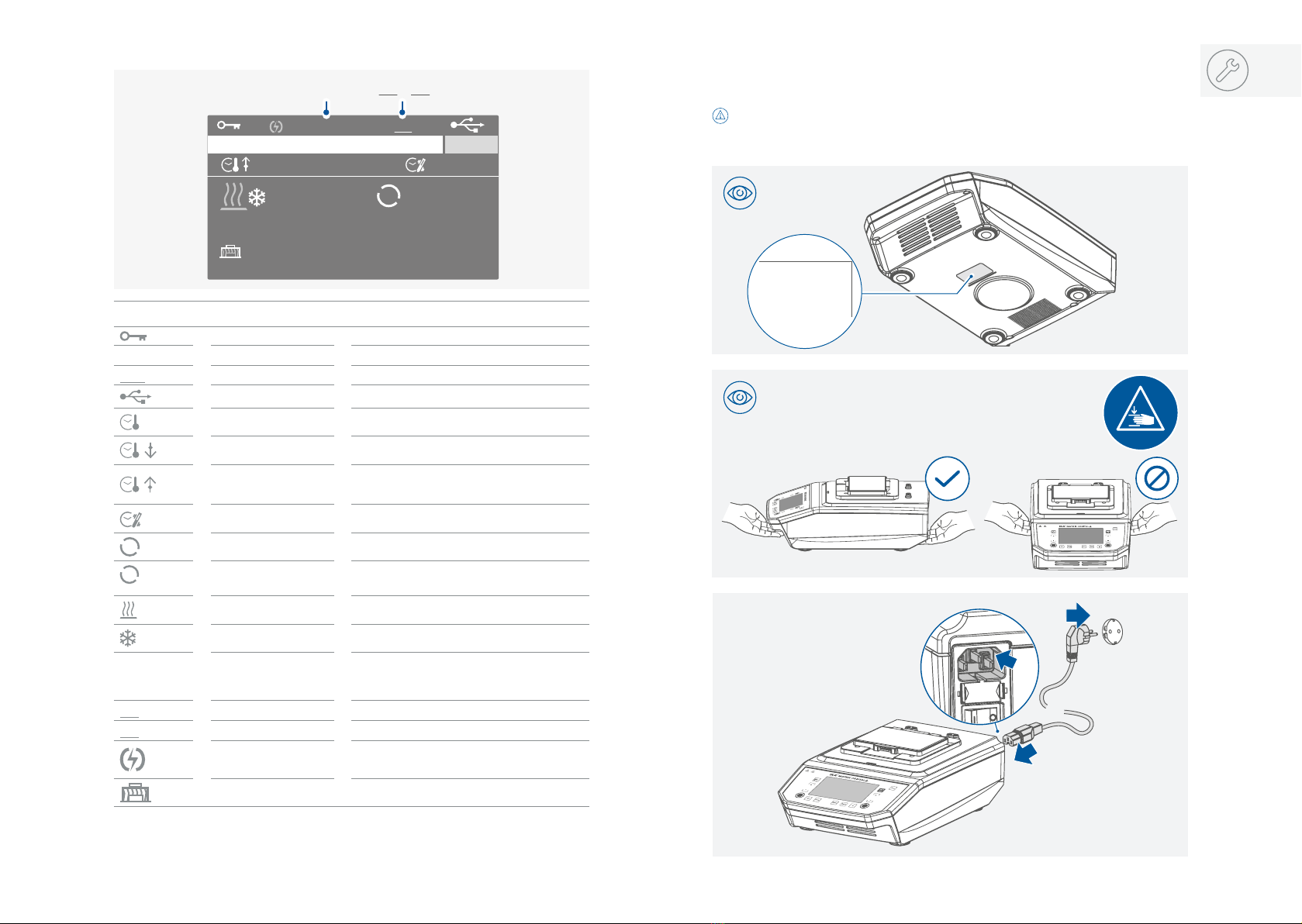
› The voltage stated on the type plate must correspond to the power voltage�
› The device can only be disconnected from the power supply by pulling out the power plug
or the connector plug�
› The device must only be operated with the original power cord set�
› The socket for the power cord must be easily accessible�
› Socket must be earthed (protective ground contact)�
› The device will automatically restart in mode B and C following any interruption to the
power supply�
/// Accessories
› Protect the device and accessories from bumping and impacting�
› Check the device and accessories beforehand for damage each time when you use them�
Do not use damaged components�
› Safe operation is only guaranteed with the accessories described in the ”Accessories” section�
/// Range of use
Indoor environments similar to that of a laboratory in research, education, commerce or
industry�
The safety of the user cannot be guaranteed:
›
if the device is operated with accessories that are not supplied or recommended by the
manufacturer�
›
if the device is operated improperly or contrary to the manufacture’s specifications�
›
if the device or the printed circuit board are modified by third parties�

10 11
1 IKA MATRIX ORBITAL DELTA PLUS
2Mains cable
3User guide
4Warranty card
5USB cable
Unpacking
› Please unpack the device carefully�
› Any damage should be notified immediately to the shipping agent (post office, railway
network or logistics company)�
IKA MATRIX ORBITAL Delta +
Garanty
1+2+3
1
2
3
4
5
Operator panel and display
A
B
C
G H I
J
K
L
N
D
E F
M
O
/// Explanation of the control elements
Item Designation Function
AGraph button Enter the graph (Speed / Time / Temperature) menu�
BTemperature (+) button Increase the temperature setting�
CTemperature (-) button Decrease the temperature setting�
DTempering button Start / stop the tempering function�
ETimer button Enter the timer menu�
F“Programs (Prog�)” button Enter the programs menu�
G“Menu“ button Touch it once: main menu is displayed�
Touch it a second time: back to the working screen�
H“Back“ button Return to the previous menu level�
IPause (II) button Touch it once: Pause the mixing and tempering function�
Touch it a second time: Restart the mixing and tempering function�
JMixing button Start / stop the mixing function�
Confirm the select menu option in menu / sub-menu�
KSpeed (-) button Decrease mixing speed setting�
Menu navigation in menu / sub-menu�
LSpeed (+) button Increases the mixing speed setting�
Menu navigation in the menu / sub-menu�
M“Quick mix“ button
Keep touching it: Start the „Quick mix“ function with the set speed�
Release it: Stop the „Quick mix“ function�
NLock button Lock / unlock the buttons�
NDisplay Screen�

12 13
Installation
/// Connection to the power supply
100 - 240 V ~
50/60 Hz
240 W
IP 21
1.
2.
!Notice!
The socket used must be earthed (fitted with earth contact)�
Observe the ambient conditions (temperature, humidity etc�) listed under “Technical Data”�
Symbol Designation Function
Lock button
symbol
Indicate the buttons are locked�
A(B / C) Operating mode
symbol
Indicate the device is in operating mode (A, B or C)�
INT
Intermittent mode symbol
Indicate the intermittent mode is activated�
USB connection symbol
Indicate the device is communicating via USB�
Timer / Counter symbol
(Tempering)
Indicate the "Timer / Counter" start condition is set to:
"Immediately" (see "Tempering" under "Timer")�
Timer symbol
(Tempering)
Indicate the "Timer" start condition is set to: "Set
temperature reached" (see "Tempering" under "Timer")�
Counter symbol
(Tempering)
Indicate the "Counter" start condition is set to:
"Set temperature reached" (see "Tempering" under
"Timer")�
Timer / Counter symbol
(Mixing) Indicate the "Timer / Counter" for mixing�
Mixing
symbol
Indicate the mixing function is activated�
00:10
Mixing in Intermittent
mode
symbol
Indicate the mixing function with intermittent mode is
activated�
Tempering (heating)
symbol
Indicate the heating function is activated�
Tempering (cooling)
symbol
Indicate the cooling function is activated�
Fast
(Moderate /
Slow)
Temperatur control rate
symbol
Indicate the tempering "Control rate" is set to "Fast
(Moderate or Slow)"�
PC PC control
symbol
Indicate the device is controlled by a PC�
PR
Program control symbol
Indicate the device is in program control mode�
Power failure
symbol
Indicate a previous power supply interruption�
IKA ThermoCover Symbol Indicate IKA ThermoCover is attached to the device�
/// Explanation of symbols on the working screen
A
IKA MATRIX 2.0 mL
Fast
actual ºC
Set ºC Set rpm
actual rpm
25.0
100.0
300
300
0:00:00
0:00:00
0:10
PC
PC / PRB / C
Note: The symbols displayed change depending on the status and settings of the device�

14 15
/// Inserting the deepwell plate (DWP) / microplate (MTP)
/// Inserting the micro test tubes
/// Attaching the exchangeable attachments
1.
2.
1.
2.
1
Click
32
A
B
C
D
E
F
G
H
1 2

16 17
/// Attaching the Cover / ThermoCover
Note: After the contact of the ThermoCover cover has been established with the device by
pressing down the button, the heating function can prevent the formation of condensate�
Operation
/// Switching on
IKA MATRIX ORBITAL Delta +
Version: 1.02.003/1.01.021
Shaker
A
IKA MATRIX 2.0 mL
Fast actual ºC
Set ºC Set rpm
actual rpm
25.0
1.0
0
300
0:00:00
0:00:00

18 19
/// Setting the temperature and starting tempering
A
IKA MATRIX 2.0 mL
Fast actual ºC
Set ºC Set rpm
actual rpm
25.0
1.0
0
300
0:00:00
0:00:00
A
IKA MATRIX 2.0 mL
Fast actual ºC
Set ºC Set rpm
actual rpm
25.0 0
300
0:00:00
0:00:00
38.0
A
IKA MATRIX 2.0 mL
Fast actual ºC
Set ºC Set rpm
actual rpm
25.1 0
300
0:00:00
0:00:01
38.0
LIMIT
1.0
LIMIT
100.0
...
0:00:00 99:59:59
25.0 38.0
max.
/// Setting the speed and starting mixing
A
IKA MATRIX 2.0 mL
Fast actual ºC
Set ºC Set rpm
actual rpm
38.0
38.0
0
300
0:00:00
0:00:10
A
IKA MATRIX 2.0 mL
Fast actual ºC
Set ºC Set rpm
actual rpm
38.0 0
0:00:00
0:00:10
38.0
A
IKA MATRIX 2.0 mL
Fast actual ºC
Set ºC Set rpm
actual rpm
38.0 220
500
0:00:01
0:00:12
38.0
500
LIMIT 300
LIMIT 3000
...
0:00:00 99:59:59
0 500
max.
Note: depending on attachments!

20 21
/// Pausing the tempering and mixing function
A
IKA MATRIX 2.0 mL
Fast actual ºC
Set ºC Set rpm
actual rpm
38.0
38.0
500
500
0:00:19
0:00:30
A
IKA MATRIX 2.0 mL
Fast actual ºC
Set ºC Set rpm
actual rpm
38.0 0
0:00:19
0:00:30
38.0 500
A
IKA MATRIX 2.0 mL
Fast actual ºC
Set ºC Set rpm
actual rpm
28.0 0
0:00:19
0:00:30
38.0 500
s
s
s
s
3
3
3
3
3
3
F
F
F
F
s
s
s
s
s
s
s
s
2
2
2
/// Restarting the tempering and mixing function
Note: During the pause status, the tempering / mixing function can be switched off
separately by touching tempering button (D) / mixing button (J)�
A
IKA MATRIX 2.0 mL
Fast actual ºC
Set ºC Set rpm
actual rpm
28.0
38.0
0
500
0:00:19
0:00:30
A
IKA MATRIX 2.0 mL
Fast actual ºC
Set ºC Set rpm
actual rpm
28.1 220
0:00:20
0:00:31
38.0 500
A
IKA MATRIX 2.0 mL
Fast actual ºC
Set ºC Set rpm
actual rpm
38.0 500
0:00:39
0:00:50
38.0 500
s
s
s
s
s
2
2
F
F
II II

22 23
/// Locking the buttons
Note: When the buttons are locked, the tempering / mixing function still can be deactivated
by touching the tempering button (D) / mixing button (J)�
1s
A
IKA MATRIX 2.0 mL
Fast actual ºC
Set ºC Set rpm
actual rpm
38.0
38.0
500
500
0:00:39
0:00:50
A
IKA MATRIX 2.0 mL
Fast actual ºC
Set ºC Set rpm
actual rpm
38.0 500
0:00:40
0:00:51
38.0 500
/// Unlocking the buttons
1s
A
IKA MATRIX 2.0 mL
Fast actual ºC
Set ºC Set rpm
actual rpm
38.0
38.0
500
500
0:00:40
0:00:51
A
IKA MATRIX 2.0 mL
Fast actual ºC
Set ºC Set rpm
actual rpm
38.0 500
0:00:44
0:00:55
38.0 500

24 25
Menu navigation and structure
///
Menu navigation
A
IKA MATRIX 2.0 mL
Fast actual ºC
Set ºC Set rpm
actual rpm
25.0
100.0
0
300
0:00:00
0:00:00
Mixing
Menu
Timer
Menu
C...
A B
Timer
Mixing
Tempering
Timer
Mixing
Tempering
Menu +
-
-
+
Back
...
Menu
Menu
Back
Note:
When touching the "Menu" button (G), the system skips directly back to the
working screen�
When touching the "Back" button (H), the system skips back to the previous menu
level screen�
/// Using the "Quick mix" function
A
IKA MATRIX 2.0 mL
Fast actual ºC
Set ºC Set rpm
actual rpm
25.0 0
0:00:00
0:00:00
38.0 500
A
IKA MATRIX 2.0 mL
Fast actual ºC
Set ºC Set rpm
actual rpm
25.0 220
500
0:00:01
0:00:12
38.0
A
IKA MATRIX 2.0 mL
Fast actual ºC
Set ºC Set rpm
actual rpm
25.0 0
500
0:00:00
0:00:12
38.0
Fast
0:00:00 10:00:00
0 500
Quick
mix
Note: When the tempering function is activated, the "Quick mix" function is not available�
›
Press the “Menu” button (G)�
›
Select right menu item by touching the speed (+) button (L)�
Select left menu item by touching the speed (-) button (K)�
› Confirm and enter the selected menu item by touching the mixing button (J)�
a) Select desired sub-menu by touching
speed (+) button (L) or speed (-) button (K)�
Activate / deactivate a function by touching the mixing button (J)�
b) Activate the editing function to a sub-menu by touching the mixing button (J)�
Edit the value by touching
speed (+) button (L) or speed (-) button (K)�
Confirm the value by
touching the mixing button (J)�
Save the new value either by touching the "Back" button (H) or by selecting "OK" with
mixing button (J)�
Note: the selected menu option is highlighted in blue on the screen and can be edited by
touching (at the same time the color change to yellow) on the
mixing button (J)�
G H
J
K
L

26 27
/// Menu details
Tempering:
Control rate:
In the "Control rate" menu option, you can select the desired control rate between "Fast", "Mod-
erate" and "Slow"� A check mark (√) indicates the control rate is activated�
Fast: Fast tempering with a certain level overshooting�
Moderate: Moderate tempering with minimal overshooting�
Slow: Precise tempering without overshooting�
Mixing:
Intermittent mode:
In the "Activate" menu option, you can activate or deactivate the "Intermittent mode"� A check
mark (√) indicates that the function is activated�
Once the "Intermittent mode" is activated, the set values for "CW time", "Stop time" and
"CCW time" will be applied� These values can be set separately�
The "CW time" and "CCW time" can be set between 00:00 [mm:ss] to 10:00 [mm:ss]�
The "Stop time" can be set between 00:05 [mm:ss] to 10:00 [mm:ss]�
Note: When either of "CW time" or "CCW time" is set to 00:00 [mm:ss], the other one can
only set to minimum 00:03 [mm:ss]�
Symbol Rotation
Direction
Graph Description
CW
0
CW
rpm
time
CCW
Factory setting:
Continuous mode in clockwise�
CW
0
CW
300
rpm
time
300
CCW
"Intermittent mode" is activated and
"CW time" / "Stop time" is set�
Note: "CW time" and "Stop time" can be
set separately�
CCW
0
CW
300
rpm
time
300
CCW
"Intermittent mode" is activated and
"CCW time" / "Stop time" is set�
Note: "CCW time" and "Stop time" can be
set separately�
CCW / CW
0
CW
300
rpm
time
300
CCW
"Intermittent mode" is activated and
"CW time" /
"CCW time" / "Stop time"
is set�
Note: "CW time" / "CCW time" and "Stop
time" can be set separately�
///
Menu structure
Menu
Factory setting
C ...
A B √Mode A
-B
-
C
Safety Password 000
-Program Program 1
-Program 2
-
Program 5
-
...
√Tempering Control rate Fast
-Moderate
-Slow
Mixing Intermittent mode -
Activate
00:10 [mm:ss]
CW time
Stop time 00:10 [mm:ss]
CCW time 00:00 [mm:ss]
√
Graph Axis scaling Automatic
00:00:00 [hh:mm:ss]Timer Mixing Timer / Counter
00:00:00 [hh:mm:ss]Tempering Timer / Counter
Start Condition Immediately √
Set Temperature Reached -
MixingAxis assignment √
Temperature √
Minimum
Minimum
3000 rpm
100 ºC
Manual Y-Axis 1: Speed
Y-Axis 2: Temperature
Maximum
Maximum
0 rpm
1.0 ºC
White -
Firmware Update Information √
°F -
Display Background Black √
√Sound Key Tone
Factory Settings
Firmware Update Information yes
Mixing 00:10 [mm:ss]
√
LanguagesSettings English
Deutsch -
... -
Units °C √
Temperature
Control rate
Tempering Fast
VersionInformation Software 1.02.003/1.01.021
CW time
00:00 [mm:ss]
CCW time
Stop time 00:10 [mm:ss]

28 29
Programs:
In the “Programs“ menu option, you can create 5 user-defined “Speed / Temperature /Time”
profiles�
In addition, you can define the control mode (Time, Temperature hysteresis and Ramp) in the
program�
You can also define the mixing direction (CW or CCW) in the program�
A program can consist of up to 5 segments�
Once a program has been selected, the following options are available:
Start: Start the selected program upon request�
When you start the selected program
, you are required to select "Infinite loop" or input "Loop
count"�
1� Infinite loop: Upon completion of the last segment, the program continues with the first
segment until the user ends the program by stopping a device function�
2� Loop count: Indicates the total number of loop cycles until program end�
Press “OK” to start the program control� Confirm the following message if you want to start
the program control, or press the “Menu” or “Back” button to end the process�
Note: At the end of the program all device functions are switched off�
Edit: Edit the selected program parameters�
Edit the selected program by pressing on the “Edit“ with mixing button (J)�
In the editing program, you can define up to 5 program segments� The selected program
segment is highlighted in blue color�
Then, you can edit, delete, insert or save the selected program segment in this program�
When editing a parameter, press the mixing button on the selected parameter� The highlighted
cursor changed into yellow color indicates that parameter can be edited�
If the “Back” button is pressed after editing, a reminding appears and ask if you want to save
the change� When you edit the program time for at least one segment, a symbol ( ) for
respective program will appear�
1� Seg No�: Segment number�
2� Speed rpm: Target speed for mixing�
3� Temp�: Target temperature�
4� Ctrl� Mode: Control Mode�
In control mode "Time" the target values and setting s of segment are valid for the duration
indicated in the column "Time"� Afterwards, the next program segment is automatically
executed�
In control mode "± x�x K": The hysteresis (tolerance) of the actual temperature to target
temperature is set (e�g� ± 0�1 K)� The target values and settings of the segment are valid until
the actual temperature reaches the target temperature +/- hysteresis for the first time�
Afterwards, the next program segment is automatically executed�
Timer:
In the "Timer" menu option, you can set "Timer / Counter" for "Mixing" and "Tempering"
separately�
You can set "Timer" value from 00:00:01 [hh:mm:ss] to 99:59:59 [hh:mm:ss]�
The tempering / mixinig function stops automatically after the set time has elapsed and the set
time appears on the display�
Note: If the tempering / mixing is stopped before the set timer value expires, the reverse
counting of the timer is interrupted�
If you set the "Timer" value to 00:00:00 [hh:mm:ss], the counter is active�
The counter automatically starts to run fom 00:00:00 [hh:mm:ss] upto 99:59:59 [hh:mm:ss]�
When the maximum value is reached, the device stops the mixing / tempering process�
Under the "Tempering" menu option, you can set the timer / counter "Start contidion" as:
Immediately: The timer / counter starts immediately when starting the tempering function�
Set temperature reached: The timer / counter starts only when the set temperature reached�
C ...
A B
Mode:
Mode A:
After power on / power failure no automatic restart of functions�
Mode B:
After power on/power failure automatic restart of functions, depending on previous settings�
Mode C:
Set values (set in mode A or B) cannot be changed� After power on/power failure automatic
restart of functions, depending on previous settings�
Graph:
Axis scaling:
In this menu you can select "Automatic" or "Manual" axis scaling�
When you select
"Automatic" axis scaling,
a check mark (√) indicates that the function is
activated�
In "Automatic" axis scaling, the X-Axis is scaled to 5 minutes and Y-axis is scaled to maximum
value�
When you select "Manual" axis scaling, you need set the maximum and minimum value for
Y-Axis ("Y-Axis 1: Speed" and "Y-Axis 2: Temperature")�
Axis assignment:
In this menu you can select "Mixing" and / or "Temperature" for axis assignment� The check
mark (√) indicates the selected options� The selected options will be used for the graph�

30 31
Interfaces and outputs
The device can be connected to a PC and operated with the laboratory software labworldsoft
®
through USB or RS 232 interface�
The device software can also be updated with a PC via the RS 232 or USB port�
Note: Please comply with the system requirements together with the operating instructions
and help section included with the software�
USB 2.0
type B
RS 232
/// USB interface
The Universal Serial Bus (USB) is a serial bus for connecting the device to the PC� Equipped
with USB devices can be connected to a PC during operation (hot plugging)�
Connected devices and their properties are automatically recognized�
Use the USB interface in conjunction with labworldsoft®for operation in “Remote” mode and
also to update the firmware�
/// USB device drivers
First, download the latest driver for IKA devices with USB interface from:
www.ika.com/ika/lws/download/usb-driver.zip.
Install the driver by running the setup file� Connect the IKA device through the USB data cable
to the PC� The data communication runs through a virtual COM port�
Note: the USB driver is uncessary for Windows 10 system� Don't install it for Windows 10
system!
Safety:
Password:
In the “Password” menu option, you can lock the menu settings by a 3-digit password (factory
setting: 000)�
If you forgot your password, please contact our service department�
Setting:
Languages:
In the “Languages“ menu option, you can select the desired language� A check mark (√)
indicates the language that is set for the system�
Units:
In the ”Units“ menu option, you can select the desired unit (°C or °F) for the temperature� A
check mark (√) indicates the unit that is set for the system�
Display:
In the ”Background“ menu option you select black or white color for the working screen�
In the ”Firmware Update Information“ menu option,
you can activate or deactivate the
“Firmware Update Information” screen at the starting of the device� A check mark (√)
indicates that the menu option is activated�
Sound:
In the ”Sound“ menu option, you can activate or deactivate the key touch sound�
A check
mark (√) indicates that the menu option is activated�
Factory Settings:
Select the ”Factory settings” option, the system requests confirmation to restore the factory
settings� Press ”OK” button to reset all the system settings to the original standard values set at
dispatch from the factory (see “Menu structure”)�
Information:
The ”Information” option offers you an overview of the most important system settings of the
device�
Control mode "RAMP" is allowed to moderate evenly with a defined slope� The segment is
closed after the target temperature has been reached�
The gradient in K/min comes from the quotient of the temperature difference and the time
specified in the current segment�
The temperature difference is calculated from the target value temperatures of the current and
preceding segment�
Note: The ramp function can only be selected from the 2nd segment�
Delete: Deletes the selected program�
If a selected program is deleted by pressing on menu option “Delete” with the mixing button (J),
all the program parameters will be emptied� The symbol ( ) disappears�
Rename:
Rename the selected program�
You can rename the selected program by touching the mixing button (J) on "Rename"� Then, you
can input a new name as required for the program with the keyboard appeared subsequently�

32 33
Commands Function
IN_PV 2 Read the actual temperature
IN_PV_4 Read the actual speed�
IN_SP_2 Rerad the set temperature
IN_SP_4 Rerad set mixing speed
OUT_SP_2 xxx Set the temperature value to xxx
OUT_SP_4 xxx Set the speed value to xxx
OUT_SP_12@n Set the WD-safety temperature with echo of the set (defined) value
OUT_SP_42@n Set the WD-safety speed with echo of the set (defined) value
OUT_WD1@n Start the watchdog mode 1 and set the time for the watchdog to n (20���1500)
seconds�
Echo of the Watchdog time�
During a WD1-event, the tempering and mixing functions are switched off�
This command needs to be send within the watchdog time�
OUT_WD2@n Start the watchdog mode 2 and set the watchdog time to n (20���1500) seconds�
Echo of the watchdog time�
During a WD2-event, the set temperature is changed to the WD safety
temperature and the motor set speed is set to the WD safety speed�
This command needs to be send within the watchdog time�
RESET Switch to normal operation mode
START_2 Start tempering function
STOP_2 Stop tempering function
START_4 Start the motor
STOP_4 Stop the motor
IN_VERSION Read software version
IN_SOFTWARE_ID Read software ID and version
”Watchdog” functions, monitoring of the serial data flow:
If, once this function has been activated (see NAMUR commands), there is no retransmission
of the command from the computer within the set time (“watchdog time”), the tempering
and mixing functions are switched off in accordance with the set “watchdog” function or are
changed to the set target values�
The data transmission may be interrupted by, for example, a crash in the operating system, a
power failure in the PC or an issue with the connection table between the computer and the
device�
“Watchdog” – mode 1:
If there is an interruption in data communications (longer than the set watchdog time), the
tempering and mixing functions are switched off and Error 2 is displayed�
“Watchdog” – mode 2:
If there is an interruption in data communications (longer than the set watchdog time), the speed
target value is changed to the WD safety speed limit and the temperature target value is changed
to the WD safety temperature limit value� The error message
Error 2 is
displayed�
The above details correspond as far as possible to the recommendations of the NAMUR
working party (NAMUR recommendations for the design of electrical plug connections for
analogue and digital signal transmission on individual items of laboratory control equipment,
rev� 1�1)�
The NAMUR commands and the additional specific IKA commands serve only as low level
commands for communication between the device and the PC� With a suitable terminal or
communications program these commands can be transmitted directly to the device� The IKA
software labworldsoft®, provides a convenient tool for controlling the device and collecting
data under MS Windows, and includes graphical entry features, for motor speed ramps for
example�
/// Command syntax and format
The following applies to the command set:
› Commands are generally sent from the computer (Master) to the lab device (Slave)�
› The lab device only sends at the computer’s request� Even fault indications cannot be sent
spontaneously from the lab device to the computer (automation system)�
› Commands are transmitted in capital letters�
› Commands and parameters including successive parameters are separated by at least one
space (Code: hex 0x20)�
› Each individual command (incl� parameters and data) and each response are terminated
with Blank CR LF (Code: hex 0x0d hex 0x0A) and have a maximum length of 80 characters�
› The decimal separator in a number is a dot (Code: hex 0x2E)�
/// RS 232 interface
Configuration:
› The functions of the interface connections between the device and the automation system are
chosen from the signals specified in EIA standard RS 232 in accordance with DIN 66 020 Part 1�
› For the electrical characteristics of the interface and the allocation of signal status, standard RS
232 applies in accordance with DIN 66 259 Part 1�
› Transmission procedure: asynchronous character transmission in start-stop mode�
› Type of transmission: full duplex�
› Character format: character representation in accordance with data format in DIN 66 022 for
start-stop mode� 1 start bit; 7 character bits; 1 parity bit (even); 1 stop bit�
› Transmission speed: 9600 bit/s�
› Data flow control: none
› Access procedure: data transfer from the device to the computer takes place only at the
computer’s request�

34 35
Error codes
Any malfunctions during operation will be identified by an error message on the display�
Proceed as follows in such cases:
› Turn off the device by using the power switch�
› Carry out corrective measures�
› Restart the device�
Error 02
Error message › WD1 error or WD2 error
Effect › Mixing function off
› Tempering function off
Solutions › Change watchdog time�
› Transmit data from PC within set watchdog time (OUT_WDx@n)�
› Check cable and plug�
Error 03
Error message › Device internal temperature is too high
Effect › Mixing function off
› Tempering function off
Solutions › Switch off the device and allow it to cool down�
› Restart the device�
Error 05
Error message › Temperature can not reach the set value after a certain time�
Effect › Mixing function off
› Tempering function off
Solutions › Switch off and restart the device�
› Send device for repair if the error message appear again�
/// Connections between device and external devices
PC 1�1 Cable:
This cable is required to connect RS 232 port to a PC�
1
2 RxD
3 TxD
4
5 GND
6
7 RTS
8 CTS
9
1
RxD 2
TxD 3
4
GND 5
6
RTS 7
CTS 8
9
PC
1
2
3
4
5
6
7
8
9
9
8
7
6
5
4
3
2
1
USB 2�0 Cable A - micro B:
This cable is required to connect USB port to a PC�
Error 24
Error message › Temperature overshoot error
Effect › Mixing function off
› Tempering function off
Solutions › Switch off the device and allow it to cool down�
› Send device for repair if the error message appear again�
Error 48
Error message › Motor overload
Effect › Mixing function off
› Tempering function off
Solutions › Switch off the device
› Decrease the speed setting or the load
/// Device firmware update
Keep your device up-to-to-date with the IKA Firmware update tool�
The firmware update can be done with a computer connected through USB-Interface�
For this, you need register on our website MyIKA first�
After registering your device IKA will inform you about available updates for your devices�
Please download the software "FWUToolSetup�zip" from our IKA service website www.ika.com�

36 37
Maintenance and cleaning
The device is maintenance-free� It is only subject to the natural wear and tear of components and
their statistical failure rate�
/// Cleaning
For cleaning disconnect the mains plug!
Use only cleaning agents which have been approved by IKA to clean the devices:
These are: water (containing surfactant) and isopropyl alcohol�
›
Wear protective gloves during cleaning the devices�
›
Electrical devices may not be placed in the cleansing agent for the purpose of cleaning�
›
Do not allow moisture to get into the device when cleaning�
› Before using another than the recommended method for cleaning or decontamination, the
user must ascertain with that this method does not destroy the device�
/// Repairs
Please send in device for repair only after it has been cleaned and is free from any
materials which may constitute a health hazard.
For repair, please request the “Decontamination Certificate” from IKA, or download printout
of it from the IKA website www.ika.com�
If you require servicing, return the device in its original packaging� Storage packaging is not
sucient� Please also use suitable transport packaging�
/// Ordering spare parts
When ordering spare parts, please indicate:
›
Device type�
›
Serial number, see type plate
› Item and designation of the spare part, see: www.ika.com, spare parts diagram and spare
parts list�
›
Software version (Briefly visible in the display when the device is switched on)�
If the action described fails to resolve the fault or another error code is displayed then take
one of the following steps:
›
Contact the service department
›
Send the device for repair, including a short description of the fault�
Error 49 - Motor hall sensor fault
Error message › Motor hall sensor signal lost
Effect › Mixing function off
› Tempering function off
Solutions › Switch off and restart the device�
› Send device for repair if the error message appear again�
Accessories
For accessiores see www.ika.com�
Exchangable attachments Tubes / Plates
Max. Drehzahl
Max.
Temperature
Min.
Temperature
IKA MATRIX AUFSATZ 0�5 ML
24 x 0�5 ml
Gefäße 2000 rpm 100 °C
RT - 15 °C
IKA MATRIX AUFSATZ 1�5 ML
24
x 1�5 ml Gefäße 2000 rpm 100 °C
RT - 15 °C
IKA MATRIX AUFSATZ 12 MM
24
x 11 mm bis 11�9 mm
Gefäße 2000 rpm
100 °C
RT - 15 °C
IKA MATRIX AUFSATZ CRYO
24 x 1�5 ml oder 2�0 ml
Cryo-Gefäße
2000 rpm 100 °C
RT - 15 °C
IKA MATRIX AUFSATZ 2�0 ML
24
x 2�0 ml Gefäße 2000 rpm 100 °C
RT - 15 °C
IKA MATRIX AUFSATZ 5�0 ML
8
x 5�0 ml Gefäße 1000 rpm 100 °C
RT - 15 °C
IKA MATRIX AUFSATZ 15 ML
8
x 15 ml Gefäße 1000 rpm 100 °C
RT - 15 °C
IKA MATRIX AUFSATZ 50 ML
4
x 50 ml Gefäße 1000 rpm 100 °C
RT - 15 °C
IKA MATRIX AUFSATZ PCR 96
96
x 0�2 ml PCR-Gefäße
1
x 96-Well-PCR-Platten
2000 rpm 100 °C
RT - 15 °C
IKA MATRIX AUFSATZ PCR 384
1
x 384-Well-PCR-Platten
3000 rpm 100 °C
RT - 15 °C
IKA CARRIER
1 x MTP
1 x DWP
3000 rpm
2000 rpm 100 °C
RT - 15 °C
IKA Abdeckung
For IKA PCR 96, IKA PCR 384, IKA 0�5 ml, IKA 1�5 ml, IKA 2�0 ml
and IKA CARRIER (MTP & DWP)�
Note: For even tempering and to protect the samples from unwanted exposure to light�
IKA THERMOCOVER
For IKA PCR 96, IKA PCR 384, IKA 0�5 ml, IKA 1�5 ml, IKA 2�0 ml
and IKA CARRIER (MTP & DWP)�
Note: Prevent the formation of condensate on vessel walls or vessel lids�

38 39
Tempering function
Heat output W 100
Heating rate K / min 6
Cooling power W 72
Cooling rate K / min 0�8
Working temperature min� ºC RT - 15
Temperature setting min� ºC 1
Temperature setting max� ºC 100
Safety temperature limit ºC 145 (fixed)
Temperature setting Buttons
Temperature setting resolution K 1�0
Temperature display TFT LCD
Temperature display resolution K 0�1
Temperature control accuracy K ± 0�5
Temperature stability K ± 0�5
Temperature homogenity K ± 0�5
Timer function
Timer / Counter range 0 second ��� 99 hours 59 minutes 59 seconds
Timer display TFT LCD
Timer setting Buttons
Timer setting resolution 1 second
Subject to technical changes!
Warranty
In accordance with IKA warranty conditions, the warranty period is 24 months� For claims under
the warranty please contact your local dealer� You may also send the machine direct to our factory,
enclosing the delivery invoice and giving reasons for the claim� You will be liable for freight costs�
The warranty does not cover worn out parts, nor does it apply to faults resulting from improper
use, insufficient care or maintenance not carried out in accordance with the instructions in this
operating manual�
Technical data
General data
Voltage VAC 100��� 240 ±10 %
Frequency Hz 50 / 60
Power input max� W 240
Fuse T4A 250V (2x)
Interface USB, RS 232
Operating mode Timer / contimuous operating / Program
Permitted on-time % 100
Permissible ambient temperature °C +5 ��� +40
Permissible relative humidity % 80
IP code according to EN 60529
IP 21
Safety class I
Overvoltage category II
Pollution degree
2
Dimensions (W × D × H) mm 200 × 350 × 125
Weight kg 10�0
Operation at a terrestrial altitude m max� 2000
Mixing function
Type of movement Orbital
Shaking stroke mm 3
Movement direction CW / CCW
Speed min� rpm 300
Speed max� rpm 3000 (depending on exchangeable attachments)
Speed adjustment resolution rpm 10
Speed setting Buttons
Speed deviation rpm ± 30
Speed display TFT LCD
Max� shaking weight kg 0�3
Table of contents
Other IKA Laboratory Equipment manuals

IKA
IKA Oven 125 basic dry User manual

IKA
IKA RV 10 control User manual

IKA
IKA Oven 125 control - dry glass User manual

IKA
IKA Vibrax VXR basic User manual

IKA
IKA mini G User manual

IKA
IKA EUROSTAR 400 digital User manual

IKA
IKA ULTRA-TURRAX T 18 basic User manual

IKA
IKA RCT basic safety control User manual

IKA
IKA Vortex 4 digital User manual

IKA
IKA M20 User manual

IKA
IKA C 5030 User manual

IKA
IKA RV 8 User manual

IKA
IKA C 7000 User manual

IKA
IKA ElektraSyn 2.0 User manual

IKA
IKA RCT basic User manual

IKA
IKA C 3000 isoperibol User manual

IKA
IKA ULTRA-TURRAX T50 basic User manual

IKA
IKA HS 260 Basic User manual

IKA
IKA RV 10 control User manual

IKA
IKA RW 16 basic User manual