Barry-Wehmiller Thiele Streamfeeder HV User manual
Manual
AutoStream - Model HV

Part Number: 901546
This Product Guide supports autoloader part number 311-0314 with serial numbers beginning
with B1011Axxx
© 2009 Thiele Technologies, Inc. - Streamfeeder. All rights reserved.
No part of this publication may be reproduced, photocopied, stored on a retrieval system, or
transmitted without the express written consent of Thiele Technologies, Inc. - Streamfeeder.
Thiele Technologies, Inc. - Streamfeeder
103 Osborne Road
Minneapolis, MN 55432-3120 USA
Tel:763.502.0000
Fax:763.502.0100
e-Mail: service@streamfeeder.com
Web: www.streamfeeder.com
Printed in the USA.

i
AutoStreAm HV mAnuAl
Contents
Before You Begin.................................................................................ii
Specications ......................................................................................v
Section 1: About the Machine .......................................................1
Section 2: Preparing for Operation ...............................................5
Section 3: Operation.....................................................................15
Section 4: Inspection and Care ...................................................17
Section 5: Mechanical Components ...........................................19
Section 6: Electrical Diagrams ....................................................33
ii AutoStreAm HV mAnuAl
Message
Conventions
DANGER signies an action or specic equipment area that can result
in serious injury or death if proper precautions are not taken.
WARNING signies an action or specic equipment area that can
result in personal injury if proper precautions are not taken.
CAUTION signies an action or specic equipment area that can
result in equipment damage if proper precautions are not taken.
ELECTRICAL DANGER signies an action or specic equipment
area that can result in personal injury or death from an electrical haz-
ard if proper precautions are not taken.
TIP signies information that is provided to help minimize problems
in the installation or operation of the equipment.
NOTE provides useful additional information that the installer or
operator should be aware of to perform a certain task.
IMPORTANT alerts the installer or operator to actions that can po-
tentially lead to problems or equipment damage if instructions are not
followed properly.
Before You Begin

iii
AutoStreAm HV mAnuAl
Warning Label
Descriptions WARNING LABELS afxed to this product signify an action or spe-
cic equipment area that can result in serious injury or death if proper
precautions are not taken.
Hazardous voltage. Contact will cause electric shock or burn. Turn off
and lock out power before servicing.
Moving parts can crush and cut. Keep guards in place. Lock out power
before servicing.

iv AutoStreAm HV mAnuAl
Make sure you thoroughly read this section to become familiar with
all the safety issues relating to the safe operation of this product.
Please read all of the warnings that follow to avoid possible injury.
Although Streamfeeder has made every effort to incorporate safety
features in the design of this equipment, there are residual risks that an
installer or operator should be aware of to prevent personal injury.
Please read all of the cautions that follow to prevent damage to this
product. This product is built with the highest quality materials.
However, damage can occur if the system is not operated and cared for
within design guidelines as recommended by Streamfeeder.
To insure proper machine operation make sure that all the safety de-
vices are installed properly and functioning. Do not attempt to defeat a
safety interlock or safety feature.
Equipment interior contains incoming 115VAC electrical power.
Bodily contact with these high voltages can cause electrocution,
which can result in serious injury or death.
safetY
Danger
Electrical Noise Electromagnetic interference (EMI) and radio frequency interference
(RFI), also known as electrical noise, do not usually cause problems.
If intense enough, however, it can cause problems for other electrical
equipment.

v
AutoStreAm HV mAnuAl
Maximum Product Size: 12 in. W x 12 in. L (305 mm x 305 mm)
Minimum Product Size: 3 in. W x 5 in. L (76 mm x 127 mm)
Min/Max Product Thickness: .003 in to .3125 in. (.076 mm - 8 mm)
Feed Belt Speed: 0-120 fpm (0-36,576 mm/min)
Load Belt Speed: 0-10 fpm (0-3,048 mm/min)
Load Belt Capacity: 300 lbs. (136 kg)
Electrical Requirements: 115vac, 60Hz, 7A
Weight: 225 lbs. (102 kg.)
Warranty: One-year limited
speCifiCations

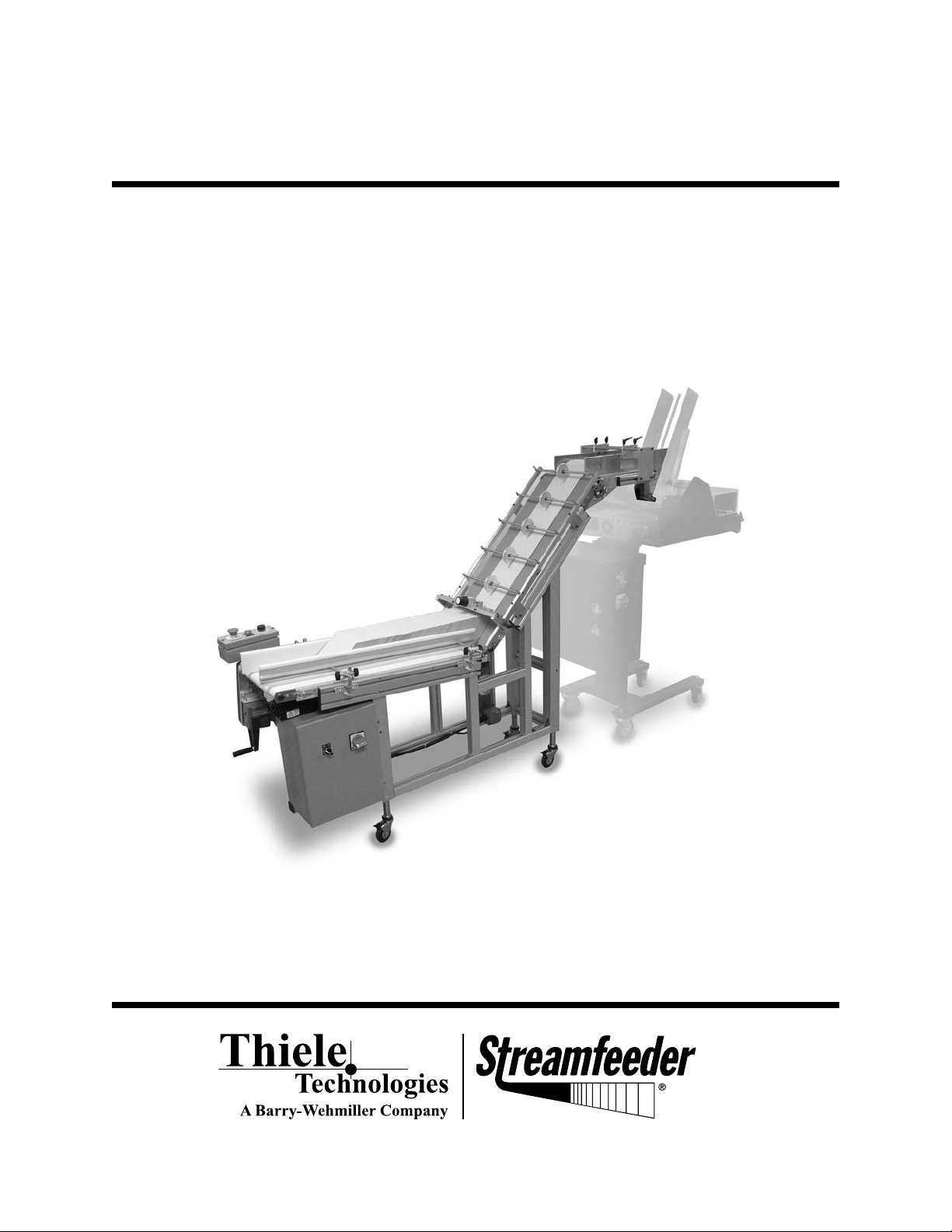
1AutoStreAm HV mAnuAl
1About the Machine
Overview
Horizontal
Conveyor
Incline
Conveyor
Discharge
Area
Horizontal
Conveyor
Belt
Hydraulic
Height
Adjustment
(refer to page 7)
Docking
Bracket
Conveyor
Side
Guides
Discharge
Belt
Discharge
Side
Guides
Product Sensor
(refer to page 13)
Separator
Hold Down
Rollers
Incline
Conveyor
Belt
Review the diagrams in this section to become familiar with names
and locations of the parts and adjustments. This will help to prepare
you for initial setup.
Locking
Casters
Control Panel
(refer to page 3)

2
AutoStreAm HV mAnuAl
Feature Description
Main Assemblies Feature Descriptions
Conveyor Side Guides The conveyor side guides help direct the product in a straight line of movement on the
horizontal conveyor.
Discharge Belt
Discharge Side Guides The discharge side guides help direct the product in a straight line of movement in the
discharge area.
Docking Bracket The docking bracket keeps the autoloader and feeder connected at the desired distance.
Hold Down Rollers Theholddownrollersoatalongthetopsurfaceoftheshingledstreamofproducttohelp
control it as it is moved upward on the incline conveyor belt to the discharge area.
Horizontal Conveyor Belt The horizontal conveyor belt moves the loaded product toward the separator gate.
Incline Conveyor Belt The incline conveyor belt lifts product from the horizontal conveyor and delivers it to the
discharge belt.
Locking Casters Four locking casters keep the autoloader in place next to the feeder
Separator The separator shingles the loaded product for its upward travel on the incline conveyor belt.
Control Panel The control panel contains the electrical connection and breaker for the unit.
(not shown, refer to page 3)
Operator Station Houses controls to operate autoloader.
(not shown, refer to page 3)
Hydraulic Height Adjustment The hydraulic height adjustment is used to change the vertical height of the autoloader.
(not shown, refer to page 7)
Product Sensor The product sensor detects when the product in the feeder hopper is low. When detected, the
(not shown, refer to page 13) autoloader will advance to feed more product.

3AutoStreAm HV mAnuAl
Operator Station
Control Panel
Controls Overview
Speed Start/Jog Emergency
Stop
On/Off
Main Power
Sensor
Connector

4
AutoStreAm HV mAnuAl
Feature Description
Controls Feature Descriptions
Speed Increases and decreases both belt speeds while maintaining the set ratio.
Start/Jog Starts or jogs conveyor belts.
Emergency Stop Emergency stop cuts power to unit.
On/Off
Main Power
Sensor Connector

5AutoStreAm HV mAnuAl
2Preparing for Operation
Overview
Condition of installment:
Warning decals must be visible to equipment
operator.
DO NOT attempt to make any adjustments while the
equipment is running. Serious injury can be caused by
exposure to moving parts.
DO NOT wear loose clothing when operating the
equipment.
When performing adjustments, always make sure to
turn off the main power switch and disconnect the
equipment from the power source. Failure to do so
can cause the risk of an unintentional start-up and
therefore exposure to moving parts which can cause
serious injury.
Any attempt to make adjustments while the equipment
is in operation could potentially damage to equipment
or parts.
To prepare the autoloader for operation, the follow-
ing setups should be made in order:
1. Positioning with the Feeder
2. Discharge Side Guide Assembly and Setup
3. Docking
4. Conveyor Side Guide Setup
5. Separator Setup
6. Hold Down Rollers Setup
7. Product Sensor Setup
8. Connect Power
9. Test to Verify Proper Setup

6
AutoStreAm HV mAnuAl
Step 1:
Positioning with the Feeder
Review
The discharge belt on the autoloader must be set
slightly higher than the feeder hopper. The correct
height depends on the product being fed and the
clearance of the wedge being used.
Objective
Correctly adjust the height of the autoloader so the
product being fed falls evenly and freely, without skew,
into the feeder hopper.
Procedure
1. Swivel the hydraulic height adjustment handle
out to the extended position.
2. Turn the handle to raise or lower the autoloader
to the desired height.
3. Swivel the handle back into place.
4. Position the side guides between the feeder side
guides.
Swivel the height adjustment handle.
Turn the height adjustment handle.
Position side guides inside feeder hopper.

7AutoStreAm HV mAnuAl
Step 2:
Discharge Side Guide
Assembly and Setup
Review
The discharge side guides help direct the product in
a straight line of movement along the discharge belt.
Each side guide is independently adjustable, both
horizontally and vertically, to accommodate different
product widths. There are two locking levers on each
side guide.
Objective
Adjust the discharge side guides to maintain uniformity
in the loaded product with no drifting or binding.
Procedure
1. Attach each side guide by sliding the mounting
holes onto the socket head cap screws on the
inside of the mounting blocks.
2. While holding the side guide in place adjust to
the desired height above the belt and tighten the
screws.
3. Thecurvedareaofthesideguideshouldt
closely to the discharge belt without making
contact.Ifthecurvedareadoesnottwell,
adjust the side guide assembly mounting block
forward or back by loosening the four socket
head cap screws on the outside of each mount-
ing block, sliding the assembly to the desired
position and retightening the socket head cap
screws.
4. Tighten socket head cap screws.
Vertical and horizontal adjustment points.
Side guides spacing with discharge belt.
Curved area
close to belt

8
AutoStreAm HV mAnuAl
Step 2:
Discharge Side Guide
Assembly and Setup
(continued)
5. Loosen the lock levers on each side guide.
6. To adjust the side guides for width, indepen-
dently adjust each side guide to within ap-
proximately 1/8” of the product positioned as it
will be received from the incline conveyor belt.
The side guides should be equidistant from the
center of the conveyor belt.
7. Tighten the locking levers.
Horizontal lock levers.
Proper horizontal side guide adjustment.

9AutoStreAm HV mAnuAl
Step 3:
Docking
Review
The autoloader and feeder are connected together by
a docking bracket, adjustable for the distance between
the feeder and the autoloader. The proper extension of
the bracket will allow the proper amount of clearance
for the product to fall, evenly and aligned, from the
autoloader discharge belt into the hopper on the feeder.
The autoloader discharge belt should be tangent to the
product stack and the returning side of the discharge
belt should slightly clear the wedge on the feeder.
Objective
Properly connect the autoloader and feeder together
using the adjustable docking bracket.
Procedure
1. Disassemble the feeder end of the docking
bracket by loosening the socket head cap
screws as shown.
2. Place docking bracket over the frame of the
feeder.
3. Tighten the socket head cap screws to secure it
in place.
4. Lock the four casters on the autoloader.
To reduce overall setup time and issues, it
is important to set up and test the feeder
before beginning setup of the autoloader.
Loosen
Docking bracket.
Docking bracket re-assembeld on feeder.
Loosen
Adjust
height
Adjust
depth
10
AutoStreAm HV mAnuAl
Step 4:
Conveyor Side Guide Setup
Review
The side guides help direct the product in a straight
line of movement along the horizontal conveyor belt.
Each side guide is independently adjustable, both
horizontally and vertically, to accommodate different
products. There are two locking knobs on each side
guide for each adjustment.
Objective
Adjust the horizontal conveyor side guides to maintain
uniformity in the loaded product with no drifting or
binding.
Procedure
1. On each horizontal conveyor side guide, loosen
the two horizontal locking kobs.
2. Move each conveyor side guide to a width
greater than the product width and equal dis-
tance from the center point of the feeder.
3. Place one piece of product on the conveyor in
the desired feeding orientation. The edges of
the product should rest equally on both sides of
the belt.
4. Move each guide as close as possible to the
sides of the product without causing binding,
curling of edges or resistance of movement. A
good starting point is 1/8” (1.6mm) from each
edge.
5. Tighten the locking knobs.
6. Loosen the two vertical locking knobs.
7. Stand the piece of product on its end on the
conveyor in the desired feeding orientation.
8. Raise or lower each side guide to support the
vertical height and weight of the product.
9. Tight the locking knobs.
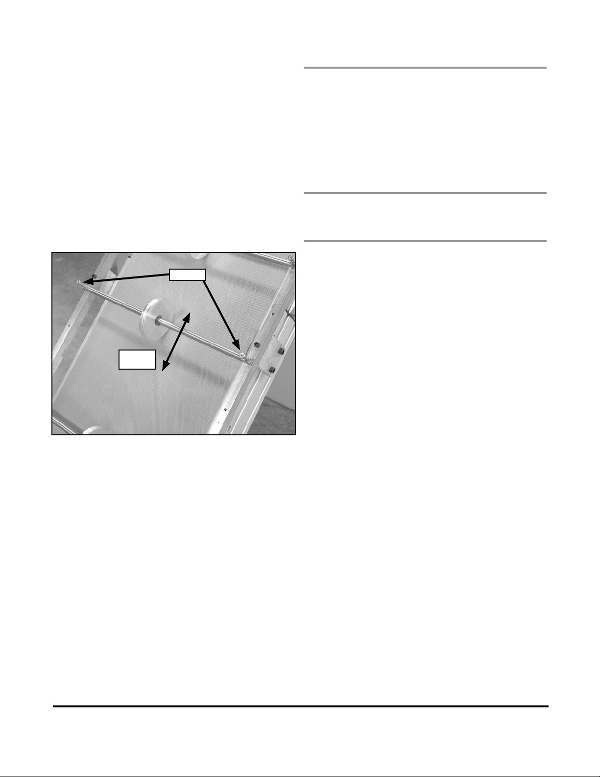
Vertical
locking
knob
Horizontal
locking
knob
11 AutoStreAm HV mAnuAl
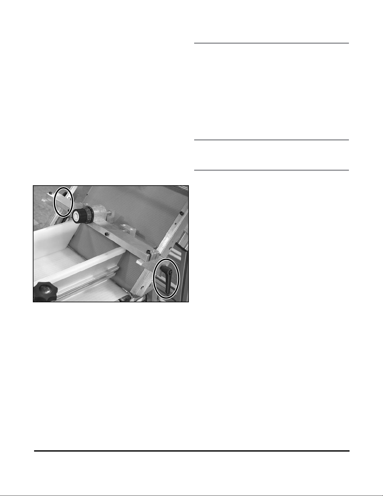
Step 5:
Separator Setup
Review
The separator shingles the product for its upward travel
on the incline conveyor belt. By moving the separator
up and down along the hold down frame, the height of
the separator is adjusted for the height of the product as
it has been loaded along the horizontal belt. To adjust
the separator for the thickness of the product, choose
one of the three slot sets. Finely adjust for the thickness
of the product by raising or lowering the gate by turning
the adjustment knob.
Objective
Adjust the separator for height and thickness of product.
Procedure
1. Loosen the locking levers on each side of the
separator.
2. Slide the separator up and down along the hold
down frame to approximately ½” above the
height of the product as it is loaded on the hori-
zontal belt.
3. Tighten the locking levers.
4. If the shingling gate is not in the desired slot set
to accommodate the product thickness, loosen
the socket head cap screws on each side.
5. Position the shingling in the desired slot set.
6. Tighten the socket head cap screws.
7. Turntheknobtoneadjusttheshinglingby
lowering it toward or raising it away from the
incline conveyor belt.
Locking levers.
12
AutoStreAm HV mAnuAl
Step 6:
Hold Down Rollers
Setup
Review
Theholddownrollersoatalongthetopsurfaceof
the shingled stream of product to help control it as it
is moved upward on the incline conveyor belt to the
discharge area. The hold down rollers can be spaced as
close as 3 inches along the hold down frame. The ideal
set up would use the least rollers necessary to manage
the product.
Objective
Set the spacing of the hold down rollers.
Procedure
1. For each hold down roller assembly, loosen the
shoulder head cap screw on each side.
2. Move each hold down roller assembly to the
desired position.
3. Tighten the shoulder head cap screws.
Adjusting hold down rollers.
Loosen
Move up
or down

13 AutoStreAm HV mAnuAl
Step 7:
Product Sensor Setup
Review
The product sensor detects when the product in the
feeder hopper is low. When detected, the autoloader
will advance to feed more product.
Objective
Properly install and adjust the autoloader product
sensor.
Procedure
1. Connect the sensor to the sensor output recep-
tacle on the external upper right side of the
control box.
2. Install the sensor mounting hardware onto the
feeder.
3. Direct the sensor at the stack of product in the
feeder hopper and adjust to the desired height.
Attach to feeder and adjust height.
Sensor
Connector
Table of contents
Other Barry-Wehmiller Packaging Equipment manuals


Popular Packaging Equipment manuals by other brands


HSM
HSM ProfiPack C400 operating instructions

PackBest
PackBest Q020 instruction manual

AETNAGROUP
AETNAGROUP ROBOPAC ROTOPLAT Use and maintenance manual

Polychem
Polychem GP44 Operation and maintenance manual

Air Packaging Machine
Air Packaging Machine H035 manual

Francotyp-Postalia
Francotyp-Postalia FPi 5020 Operator's manual