GP44 Semi-Automatic Strapping Machine
OPERATION -8-
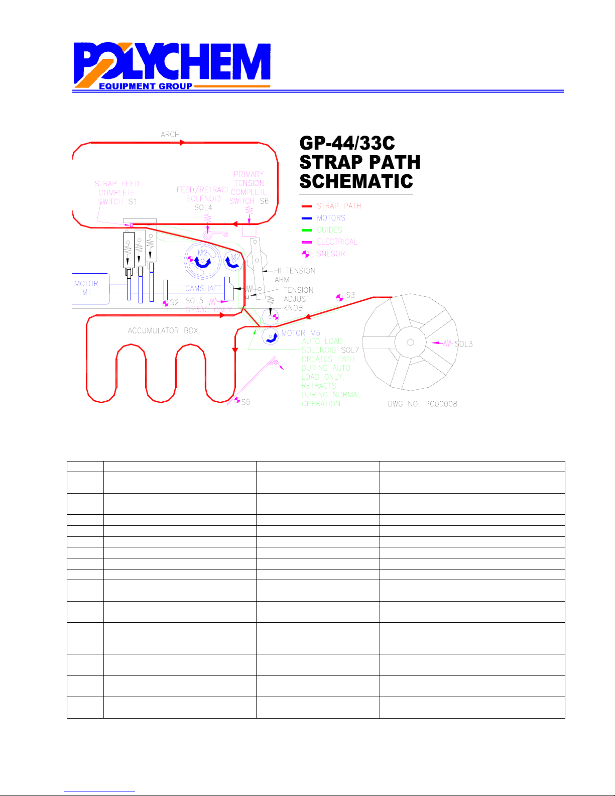
KEY COMPONENTS (Refer to Strap Path Schematic)
Ref Description Location Function
EB1 Electric Brake Cam Motor (M1) In back of M1 Stops cam in home position, primary
tension position and final tension position.
EB2 Electric Brake Feed/Retract Motor
(M2)
In back of M2 Stops feed/retract motor when strap is not
feeding or retracting
EB3 Reel Brake On reel shaft Stops reel when not loading strap
M1 Cam Shaft Motor Under conveyor Rotates camshaft
M2 Strap Feed/Retract Motor Under conveyor Rotates feed/retract wheels
M5 Accumulator Load Motor Before accumulator box Feeds strap into the accumulator box
SA 1 Tabletop Safety Switch Side of conveyor top Verifies that the tabletop is closed
SA2 Tabletop Safety Switch Side of conveyor top Verifies that the tabletop is closed
SOL3 Real Brake Solenoid On reel shaft Provides some drag on the reel to prevent
it form “free wheeling”
SOL4 Strap Feed/Retract Solenoid Under conveyor Presses the strap against the feed/retract
wheel to feed/retract strap
SOL7 Initial Feed Solenoid Behind accumulator box Engages only during initial load to create a
path for strap to initially load into the
strapping head/arch.
S1 Strap End Detect Switch Under slide plate Detects if the end of the strap has made it
entirely around the arch
S2 Camshaft Home Proximity Switch Near camshaft Stops the cam in the home position (TR12)
and the primary tension position (TR 93).
S3 Strap Present Proximity Switch After reel Verifies that strap is present and flowing
into the accumulator box