Barry-Wehmiller BW Integrated Systems Streamfeeder V-1400IJ User manual

V-1400IJ
Inkjet Feeder
Manual

© 2018 Streamfeeder - BW Integrated Systems. All rights reserved.
No part of this publication may be reproduced, photocopied, stored on
a retrieval system, or transmitted without the express written consent of
Thiele Technologies, Inc. - Streamfeeder.
Streamfeeder - BW Integrated Systems
315 27th Avenue NE
Minneapolis, MN 55418 USA
Tel:(763) 502-0000
Fax:(763) 502-0100
e-Mail: service@streamfeeder.com
Web: www.streamfeeder.com
Printed in the USA.

i
V-1400IJ Manual
Contents
Safety Information ........................................................ii
Specications ..............................................................iv
Section 1: About the Machine .......................................................1
Section2: InstallingtheMachine ..................................................5
Section3: PreparingforOperation ............................................. 11
Section4: HowtoOperate ...........................................................17
Section5: Troubleshooting .........................................................20
Section6: InspectionandCare ...................................................22
Section7: MechanicalComponents ...........................................29
Section8: ElectricalComponents...............................................45
ii V-1400IJ Manual
Message
Conventions
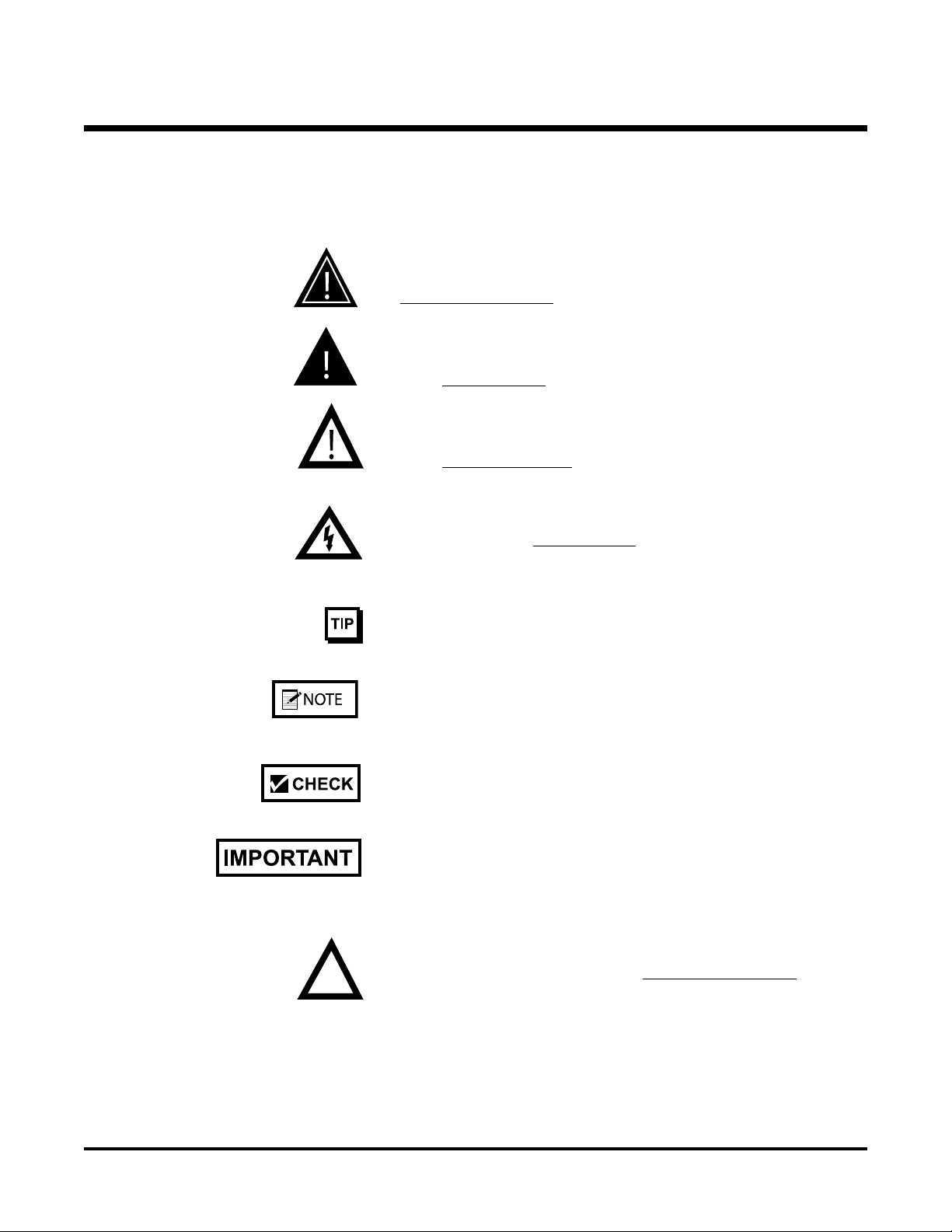
DANGER signies an action or specic equipment area that can result
in serious injury or death if proper precautions are not taken.
WARNING signies an action or specic equipment area that can
result in personal injury if proper precautions are not taken.
CAUTION signies an action or specic equipment area that can
result in equipment damage if proper precautions are not taken.
ELECTRICAL DANGER signies an action or specic equipment
area that can result in personal injury or death from an electrical haz-
ard if proper precautions are not taken.
TIP signies information that is provided to help minimize problems
in the installation or operation of the feeder.
NOTE provides useful additional information that the installer or
operator should be aware of to perform a certain task.
CHECK signies an action that should be reviewed by the operator
before proceeding.
IMPORTANT alerts the installer or operator to actions that can poten-
tially lead to problems or equipment damage if instructions are not
followed properly.
WARNING LABELS afxed to this product signify an action or spe-
cic equipment area that can result in serious injury or death if proper
precautions are not taken.
Before You Begin

iii
V-1400IJ Manual
Message
Conventions
Before You Begin
Avoid injury. Do not reach around guards.
Hazardous voltage. Contact will cause electric shock or burn. Turn off
and lock out power before servicing.
Moving parts can crush and cut. Keep guards in place. Lock out power
before servicing.
Pinch point. Keep hands and ngers clear.
Moving parts can crush and cut. Keep guards in place. Lock out power
before servicing.

iv V-1400IJ Manual
Maximum Product Size: ...................... 14 W x 18 L in (355 x 457 mm)
Minimum Product Size: ...................... 2 W x 3 L in (51 x 76.2 mm)
Min/Max Product Thickness: ............. .003 -1.0 in (.07 - 25.4 mm)
Belt Speed: ............................................. 7800 in/min (19,812 cm/min)
Drive: ...................................................... DC motor
Electrical Requirements: ...................... 115/230vac, 50/60Hz, 3A
Multiple Voltage Interface Relay: ........ 24vac, 115vac, 5vdc, 12vdc, 24vdc
Weight: ................................................... 47 lbs. (21.3 kg)
speCifiCations

v
V-1400IJ Manual
Make sure you thoroughly read this section to become familiar with
all the safety issues relating to the safe operation of this product.
Thiele Technologies - Streamfeeder hereby declares that this product
is in conformance with the following standards:
Machinery Directive 98/37/EC
Low Voltage Directive IEC/EN/CSA/UL 60950
Emissions - EN55014-1
Immunity - EN55014-2
The technical file for these products is maintained at the corporate
headquarters of Thiele Technologies - Streamfeeder in Minneapolis,
Minnesota USA.
Ce CertifiCation

1V-1400IJ Manual
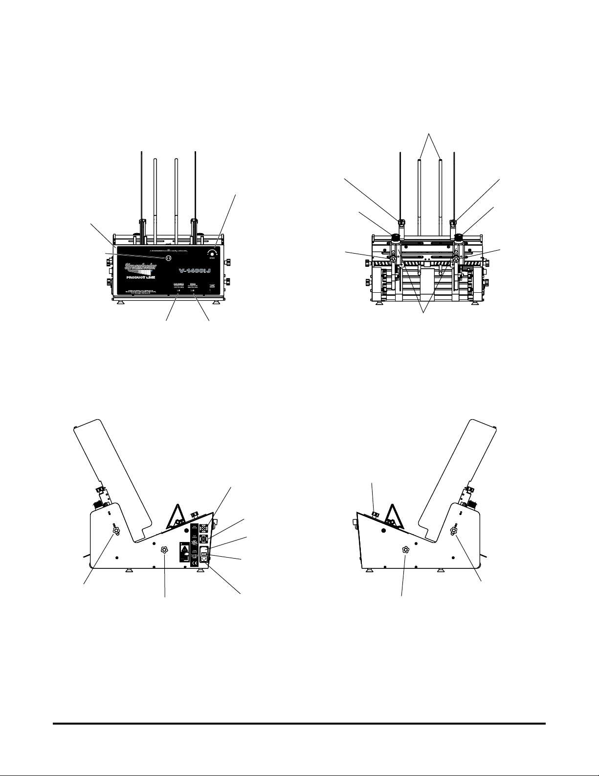
Gate
Gate
Table Top/Shell
Wedge
Carriage
Hinged Panel
(Controls Access)
Side Guides
Adjustable
Product
Support Rods
1About the Machine
The V-1400IJ is designed for reliability, exibility, and ease of use
with a variety of vacuum and non-vacuum bases.
All parts required for setup, loading, feeding, and easy operator con-
trol are combined into one compact unit.
Review the main assemblies below to become familiar with names
and locations of feeder parts and adjustments. This will help to prepare
you for initial setup.
Features
Main Assemblies

2
V-1400IJ Manual
Main Assemblies Feature Descriptions
Feature Description
Side guides Single knob adjust (one on each side) allows lateral adjustment from each
side for different size product.
Side guide adjustments Dual-knob design allows you to move side guides together or apart for
different size product. Can be positioned equally or offset. (Note: Single-
knob design also available.)
Gates and adjustments Single or double gates mounted above the carriage housing the feed belts.
This device provides a curvature to help preshingle stacked product.
When properly adjusted, a clearance is created to help singulate and feed
product.
Adjustable Product Support Rods Rods can be adjusted laterally for support of wider products.
Wedge and adjustments Lifts the product to keep it off the table top, reduces excessive contact with
the feed belts, and helps push the product against the curvature of the
gate assembly. To achieve proper lift, adjustment wing-nuts and locking
levers allow you to slide the wedge to various positions and angles.
Shell One piece shell for mounting of all sub-assemblies and components.
Easy access to controls Located in rear of feeder. Allows for easy assembly and servicing of
control and other electronic components.
Removable carriage Houses the feed belts which provides the friction and motion necessary to
pull individual product from the bottom of the stack and through the gate
assembly. Easy to remove for feed belt replacement.
Lateral feed belt positioning Single knob adjust (one on each side) allows for two outside belts to be
adjusted laterally depending on product size and feeding characteristics.
3V-1400IJ Manual
Control Features
Run Status
Connector
AC Power Cordset
Connector
Run Enable
Connector
Fuse Holder
Power On/Off
Switch
Gate
Adjust Knob
Gate
Adjust Knob
Side Guide
Lock Knob Side Guide
Lock Knob
Gate
Lock Knob
Gate
Lock Knob
Belt Adjustment
Knob
Side Guide
Adjustment
Knob Belt Adjustment
Knob
Side Guide
Adjustment
Knob
Gates
Wedge
Adjustment
Knob
Pre-gate Bars
Variable
Speed
Control
Speed
Switch
Run Enable
Switch
Panel
Open/Close
Latch
On Delay
Adjust
(inside panel
on circuit
board)

4
V-1400IJ Manual
Control Features Descriptions
On Delay Adjustment
Feature Description
Variable speed control This dial switch (labeled Speed) allows the feeder speed to be
synchronized with a vacuum or non-vacuum base. Turning counter-
clockwise decreases speed; clockwise increases speed. Note: Feeder
motor stops if turned completely counter-clockwise.
Run Enable switch This slide switch allows you to use the feeder “stand- alone” or with the
run enable input interface.
Speed switch This slide switch allows you to
AC power cordset connector Cordset plugs into this connector to provide feeder with power from a
grounded and fused outlet.
Power On/Off Toggles AC power On or Off.
Fuse holder Contains two replaceable 5-Amp, 5x20 mm time delay fuses.
IMPORTANT: Always make sure power module is replaced exactly as
removed so that “115” is always visible on 115V models and "230" is
always visible on 230V models. Failure to follow this caution can result in
damaged electrical parts.
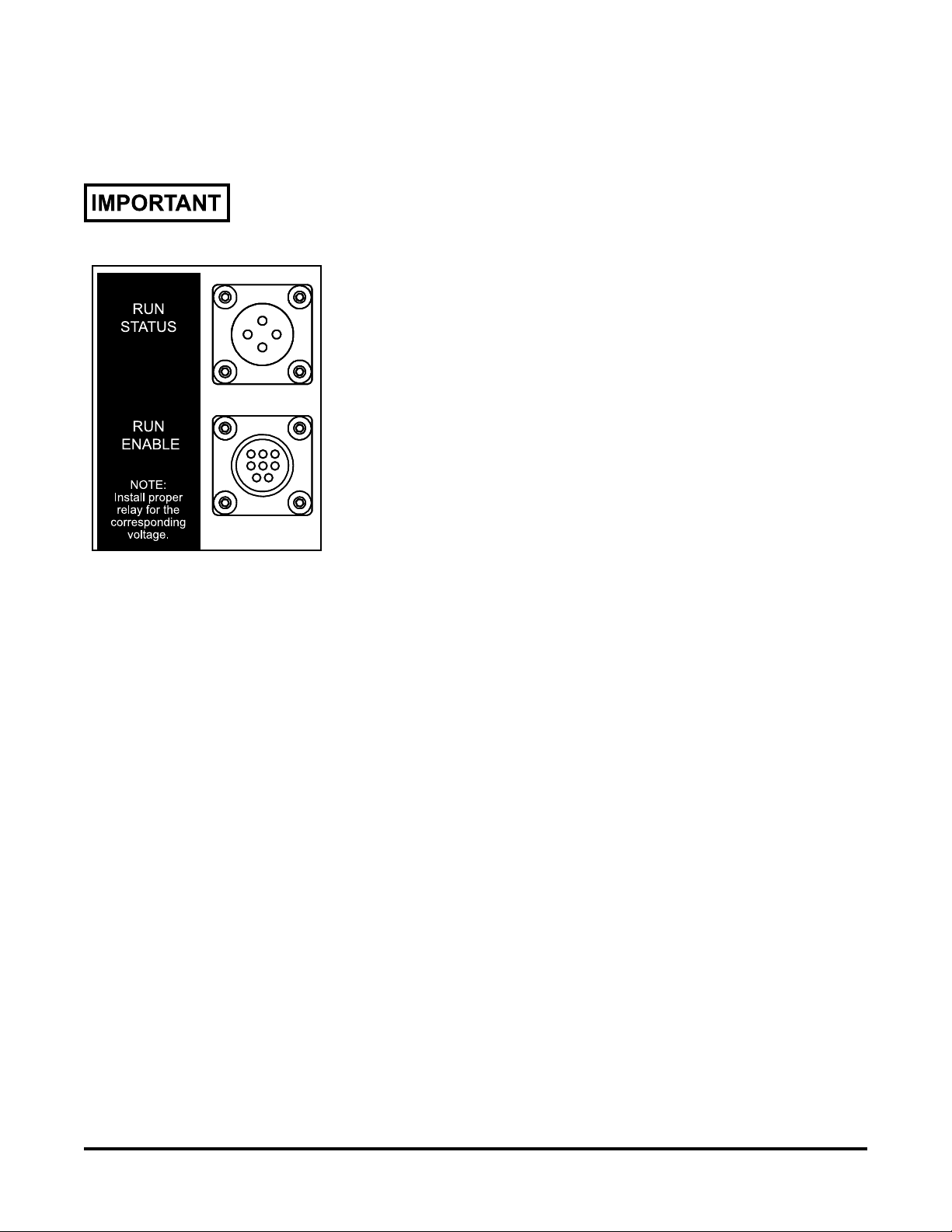
Run Status connector An interface available for host systems. Provides feedback to host system
whether the feeder is running or not.
Run Enable connector This 4-pin connector is used to carry start/stop signals from a vacuum or
non-vacuum base to the feeder.
On delay adjust Located on circuit board on inside of panel. See photo below.
Used to delay (or synchronize) feeder startup with base startup. Range is
adjustable from 0 to 12 seconds (factory set at 0 seconds).

5V-1400IJ Manual
When performing initial installation, always make sure you turn Off the main power switch and disconnect all equipment from the electrical
power source. Failure to do so can expose you to a potential startup and moving parts which can cause serious injury.
Do not attempt feeder installation while the feeder and machine of application are running. Failure to do so can expose you to moving parts which
can cause serious injury. Do not wear loose clothing when operating the feeder.
Avoid turning on the feeder or making initial adjustments until all parts are secured. Failure to do so can cause damage to equipment.
This section provides information on installing the V-1400IJ onto a
vacuum or non-vacuum transport base.
Information for a particular application typically includes procedures
for basic parts removal, feeder mounting and alignment, and cable
connections for power and control interface. Information that relates
to specic adjustments you must make to feeder prior to startup and
operation is found in Section 3, “Preparing for Operation.”
2Installing the Machine
Vacuum Base
Installation for
Shuttle Feed Bases
Installation of the V-1400IJ onto various types of vacuum and non-
vacuum bases is a relatively simple procedure. Several minor modi-
cations to the vacuum base are required prior to mounting, wiring, and
aligning the feeder.
To install the feeder onto a shuttle feeder vacuum base, perform the
following steps:
1: Repositioning front side guides
2: Removing back jogging plate/back hopper guide
3: Raising hopping rollers
4: Disabling the shuttle
5: Initial positioning of feeder
6: Providing AC power to feeder
7: Connecting run enable input
8: Checking product discharge from feeder
Included with your V-1400IJ 230V feeder is an Allen Wrench Set (P/N 23511CC1). These tools are designated for Service Personnel only.
6
V-1400IJ Manual
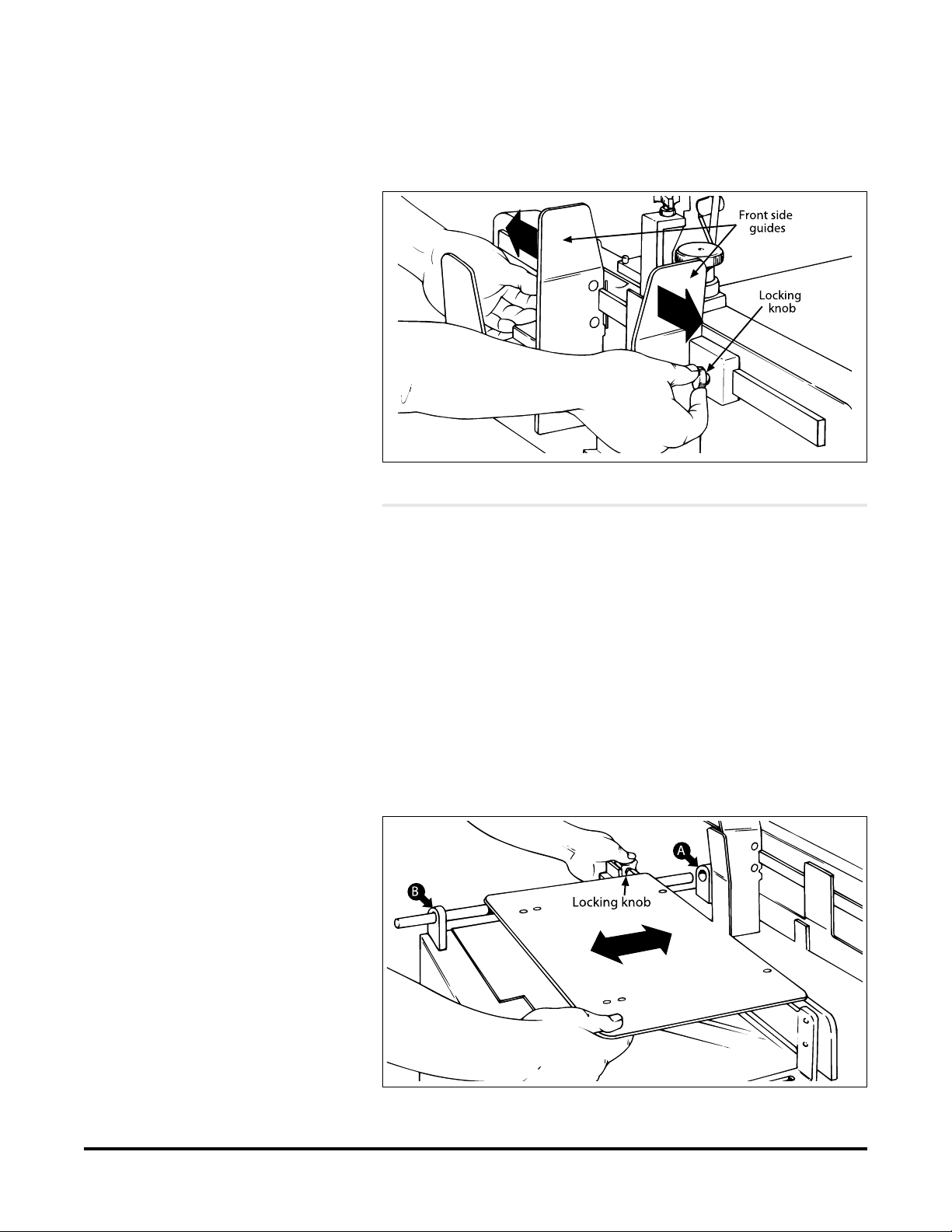
1. Loosen locking knobs at both side guides.
2. Slide each side guide to the outermost position. Do not lock in
place.
STEP 2:
Removing Back Jogging
Plate/Back Hopper Guide
STEP 1:
Repositioning Front
Side Guides
Front Side Guides Being Repositioned
1. Loosen each of the setscrews at the two shaft housing assem-
blies A and B.
2. Slide shaft end closest to the vacuum base gate out of housing
A (with jogging plate/hopper guides still attached). Slide shaft
back far enough on housing B to allow removal of jogging
plate/hopper guides.
3. Loosen locking knob and slide jogging plate/back hopper
guide off of shaft and away from the surface of the vacuum
base.
4. Return shaft end to housing B. Lock setscrews in both housing
assemblies.
Back Jogging Plate/Back Hopper Guide Removal

7V-1400IJ Manual
1. Locate the gate adjustment knobs and turn completely in a
clockwise direction to raise hopping rollers.
2. Then, locate the vertical adjustment lever on the hopping roll-
ers assembly and push down all the way. This will raise the
feed rollers to highest vertical position possible, thus making
for maximum clearance.
STEP 3:
Raising Hopping Rollers
If additional control of material is required
during feeding, you may choose to keep the base’s
hopping roller assembly in the down (or normal)
position.
1. Remove side access panel from vacuum base enclosure.
2. Locate the reciprocating arm and reciprocating block directly
beneath the underside of shuttle.
3. Using a box wrench, remove the hex-head rod end bearing
bolt holding the reciprocating arm to the reciprocating block.
4. Once the bearing bolt is removed, the reciprocating arm is ef-
fectively disconnected. As the shaft is connected to the shuttle
base plate on the other end, simply allow the shaft to hang
in-position, with no further disassembly.
5. Make sure the base plate of shuttle is all the way forward
(toward the vacuum base gate).
Using the Adjustments to Raise Hopping Rollers
STEP 4:
Disabling the Shuttle
To prevent any accidental startup of shuttle
motor and to eliminate the hazard of moving
parts, you can prevent accidental startup by
either disconnecting vacuum base from AC
power at the outlet, or you can remove the
internal AC power fuse (located behind the
access door of the vacuum base).
Disabling the Shuttle from Inside the Access Panel

8
V-1400IJ Manual
1. Lift the feeder onto the top plate of the vacuum base and slide
forward toward the vacuum base gate.
2. Center the feeder between the two side guides as you posi-
tion the feeder fully forward. To verify centering, sight down
the center of the feeder gate, making sure it is in-line with the
vacuum base gate.
3. Trap the feeder in-between the vacuum base side guides by
sliding each in toward the side plates of the feeder until they
gently touch. Tighten side guide knobs to secure in position.
STEP 5:
Initial Positioning
of Feeder
1. Connect IEC320 end of power cord to the feeder (at the power
inlet module).
2. Connect three-prong end to nearest AC voltage power source.
Positioning the Feeder on the Vacuum Base
STEP 6:
Providing AC Power
to Feeder
Please verify that the voltage shown at the power
inlet module matches the incoming voltage from
the power source.
9V-1400IJ Manual
Using the run enable cables supplied for host interface applications:
Dry Contact Run Enable
1. Ensure power is not applied and power cord is disconnected
from feeder.
2. Connect the run enable cable to the top male eight-pin thread-
ed connector on the feeder.
3. At the host equipment, locate start/stop control circuit.
4. Route run enable input cable from the feeder to the host sys-
tem.
5. Interface the leads of the interface cable to the host start/stop
circuit.
6. Connect power cord to feeder.
AC/DC Run Enable
1. Ensure power is not applied and power cord is disconnected
from feeder.
2. Connect the run enable cable to the bottom female eight pin
threaded connector on the feeder.
3. At the host equipment, locate start/stop control circuit.
4. Determine the exact run input voltage required by checking
host start/stop control circuit.
5. Interface the leads of the interface cable to the host start/stop
circuit.
6. The appropriate coil relay must be installed into the feeder. To
do this, carefully open panel door.
7. Locate K1 relay slot on the control board and insert the appro-
priate relay from the supplied kit (P/N 311-0090). Close panel
door on the feeder. (See electrical diagram).
8. Connect power cord to feeder. As product leaves the feeder
gate cylinder, the trailing edge must be under the hold-down
as the leading edge is entering the vacuum base transfer sec-
tion. In otherwords, there must be a good transfer of product
from the feeder hold-down to the vacuum base transfer sec-
tion.
Run Status Signal
This is a congurable dry contact used to monitor the feeder’s
status.
The host equipment will connect to the green wire and the red
wire, which are located in both run enable cable sets.
STEP 7:
Connecting
Run Enable Input
This procedure should be performed only by a
qualied technician.
Run Status/Enable Connectors

10
V-1400IJ Manual
To verify:
1. Slide feeder back far enough to clear the vacuum base side
guides. If necessary, loosen the knobs on both side guides and
pull to the outside slightly to allow movement of the feeder.
2. Insert a piece of product under the hold-down in such a way
that approximately 2/3 of the leading edge is extending out
beyond the feeder (Figure 2-7).
3. Slide feeder back into position, making sure it is again cen-
tered between the side guides. As you do so, also make sure
that the leading edge of the product moves into the transfer
section of the vacuum base unobstructed.
STEP 8:
Checking Product
Discharge from Feeder
Make sure rollers on vacuum base are raised in
the highest vertical position so that it does not
interfere with the product.
Checking for Proper Product Discharge from Feeder to Vacuum Base
4. Check to make sure the product is still under the hold-down
roller bearings and also resting on the vacuum base transfer
section.
5. Trap the feeder in-between the side guides until they gently
touch. Tighten side guide knobs.

11 V-1400IJ Manual
3Preparing for Operation
When performing initial feeder adjustments prior to operation, always make sure you turn Off the main power switch and
disconnect all equipment from the electrical power source. Failure to do so can expose you to a potential startup and moving parts
which can cause serious injury.
Do not attempt to make any adjustments while the feeder and machine of application are running. Failure to do so can expose you
to moving parts which can cause serious injury. Do not wear loose clothing when operating the feeder.
Avoid making adjustments with loose or unsecured parts. This can potentially damage parts.
Once the V-1400IJ is installed on your host system, you are then ready
to prepare the machine for operation. To do so, perform the following
steps:
1: Lateral feed belt adjustment
2: Gate/knockdown adjustment
3: Side guide setting
4: Back wedge adjustment
5: Verifying proper installation
STEP 1:
Lateral Feed Belt
Adjustment
Smaller size product may use only the middle belt where as larger
product will likely use the two outside feed belts. The middle feed
belt is stationary and has no lateral adjustment. Since this belt is
located exactly in the center, it should be used as reference for the bal-
ance of the feed belt set-up. If the outside belts are used, they should
be positioned towards the outside edge of the product for the benet of
drive and support. They are adjusted using the knobs located on each
side of the feeder.
Belt adjustment knob
12
V-1400IJ Manual
Excessive lowering of the gate assembly can damage product or lead
to premature wear of the O-rings or feed belts.
A wider gap between product and belt provides
the highest tolerance for curled and bent edges.
Lift gate assembly upward to insert product
Feeding problems will occur with either too much
product in the hopper, or too large a gap between
the gate assembly and the product.
When feeding product with varying thickness,
it may be necessary to adjust the two gates
individually for the different thicknesses. Use one piece thickness to set gap
Slip product under
gate
Pull knob up
Move product back
and forth
Test for slight
drag
Turn knob
counterclock-
wise to lower
(or decrease
gap)
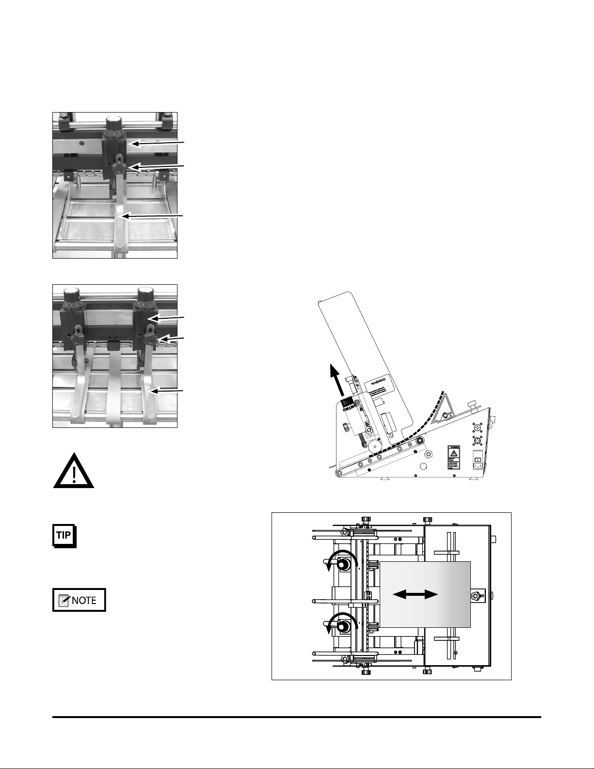
STEP 2:
Gate/Knockdown
Adjustment
Decide whether one or two gates will be needed. This is usually based
on the material size and the function of separating. They can be placed
either over the belts or over the void between belts.
1. Position the gate (either over the middle feed belt or the void
between the belts) and position the knockdown approximately
1/16" above product (or a gap which allows unimpeded feeding).
Tighten the lock knob.
2. Slide a single piece of product between the feed belt and the gate.
3. Rotate the gate adjustment knob either up or down until the
product can be pulled from under the gate assembly with a slight
amount of drag.
4. Repeat the drag tests and adjust as needed to achieve acceptable
clearance.
5. When using two gates, position each gate and repeat steps 1
through 4.
Single gate over the middle belt
Gate
Gate
Lock knob
Lock knob
Knockdown
Knockdown
Two gates over the outer belts

13 V-1400IJ Manual
STEP 3A:
Side Guide Adjustment
1. Loosen each side guide lock knob. This will allow you to move
each side guide individually from side to side.
2. Each guide is attached by a pin and slot mechanism allowing the
guide to adjust vertically approximately ½ inch. To move over
a feed belt, lift the side guide and move it laterally. After it has
passed over the belts, push the side guide down in the slot.
Side guide in down position
Side guide in up position
Center
product
on
middle
belt
Loosen
lock knob
Lift side
guides
Move side guides laterally over belts
Lift side
guides
Loosen
lock knob
Position
side
guides
3. Center the product to be run on the middle belt and position
both side guides close to the edge of the product (approximately
1/16th inch) by turning the side guide adjustment knobs.
4. Place a handful of pre-shingled product in the hopper and against
the gate(s).
5. Test run to assure proper feeding and singulation.
6. Tighten the side guide lock knobs to secure the position.
Table of contents
Other Barry-Wehmiller Packaging Equipment manuals


Popular Packaging Equipment manuals by other brands

Signode
Signode BXT3-13 Service manual

EDM Product
EDM Product 07586 instruction manual

Polychem
Polychem PHT801 Operation manual and spare parts list

quadient
quadient LAN installation guide

Lacor
Lacor EXTREME 69355 Instructions for use and maintenance

Pro Mach
Pro Mach Wexxar BEL Series Operation & service manual

Genesis
Genesis TP-501 Operation manual and spare parts list

Polychem
Polychem SP3100 Operation manual and spare parts list

AirSaver
AirSaver F2 Safety instructions, setup & installation manual

Oliver
Oliver 1808-D User's operation

hawo
hawo hd 680 DE instruction manual

strapex
strapex STR 66 operating instructions


