Scope:
EXcite
USER MANUAL
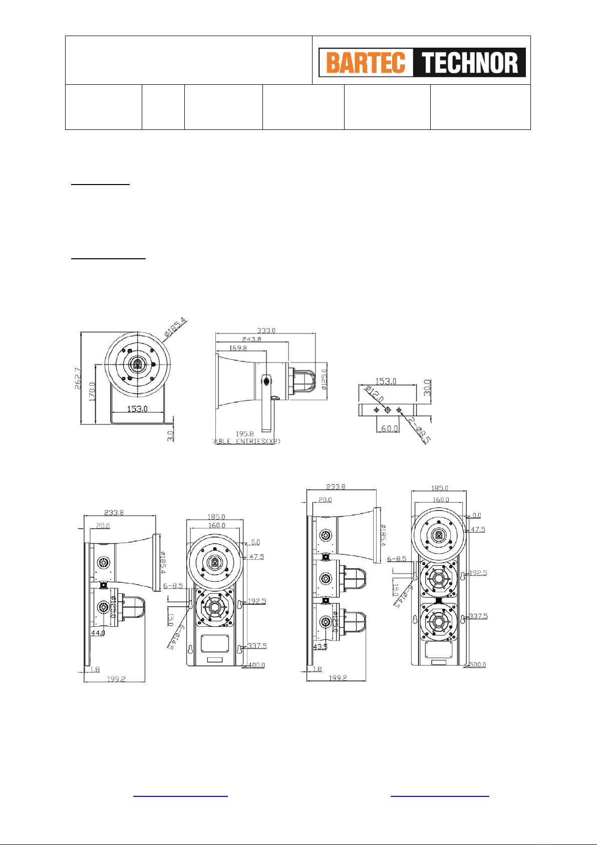
BHB 125 / BHB 150
WEB: www.bartec-technor.no PHONE: +47 51 84 41 00 E-MAIL: mail@bartec-technor.no
1.0 INTRODUCTION
BHB-125 / 150 series Explosion-proof sounder/horn & beacon are designed according to EN/IEC 60079-0,
EN/IEC 60079-1 and EN/IEC 60079-31 standards. Enclosure material is Stainless Steel (BHB 125) or GRP
(BPB 150). This product is certified for use and installation in Zone 1 and Zone 2 areas with gases groups
of IIA, IIB, IIC and temperature classification of T4~T6. It specially applies to Oil & Gas, Offshore Platform,
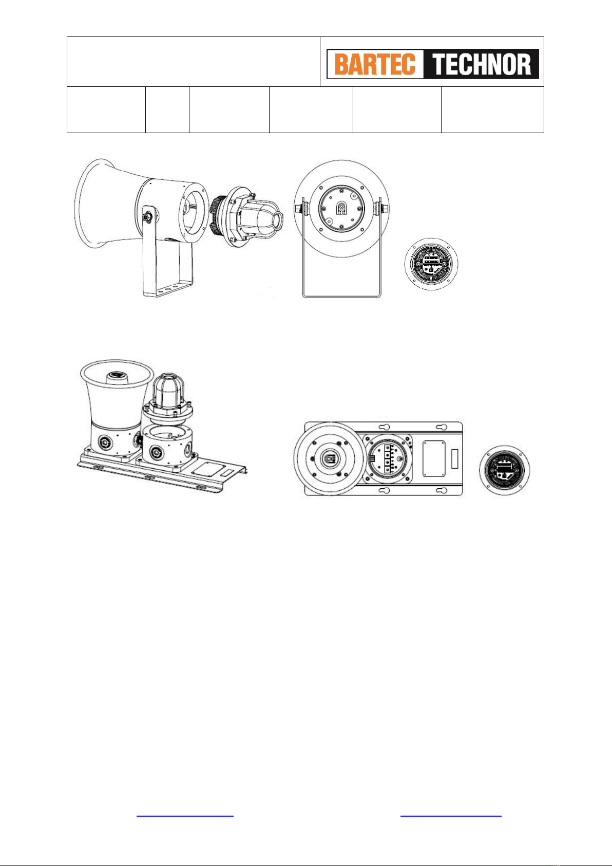
Chemical, Petrochemical, Refinery and Marine Industries etc. Users can choose from single or combination
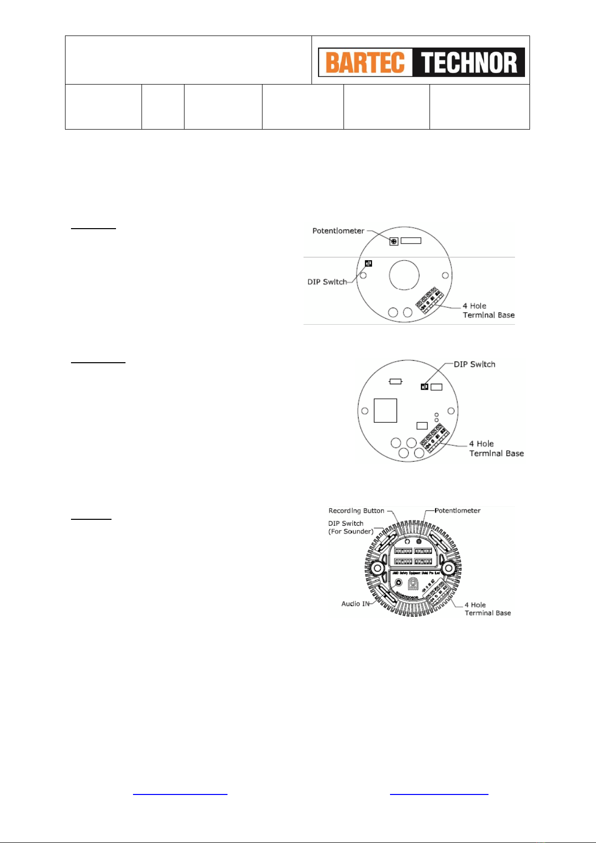
types. The design of 3 in 1 sounder, loudspeaker and beacon is unique. According to user control system, 4
stages of alarm tones can be sent out, from less critical stage (stage 1) to the most critical stage (stage
4). 64 tones are selectable. Tone can be preset during installation. At the same time, four stages of alarm
light can also be sent out.
2.0 EXPLOSION PROOF LABELING
All products have a rating label which carries the following important information:
Product order no.: e.g.
BHB125RX10DCARDN
(Refer to the datasheet for product order selection)
Input voltage: up to 48V DC or 100-254V AC
Code: Ex d IIC Txx Gb
Ex tb IIIC Txx
ATEX Marking: Gas Group and Category: II 2GD
CE Mark:
Warning: DO NOT OPEN WHEN AN EXPLOSIVE GAS ATMOSPHERE IS PRESENT
Note; exact information is given on the actual label, ref also example on page 1
3.0 TYPE APPROVAL STANDARD
The BHB 125/150 series have been approved to the following standards:
IEC/ EN 60079-0General requirements
IEC/ EN 60079-1Flameproof enclosure “d“’
IEC/ EN 60079-31 Dust atmosphere “t”