Basta Boatlifts Over-Center 4.5k37 User manual

READ complete manual CAREFULLY
BEFORE attempting assembly or operation
11/21
L392-0098D
TM
Over-Center Hydraulic Aluminum Lift
4,500 lbs Capacity Models 4.5k37 & 4.5k53
1-866-GO BASTA
www.gobasta.com
ASSEMBLY
INSTALLATION
REPLACEMENT PARTS
Copyright 2018 Basta, Inc.
©
Basta, Inc. Bellevue, WA 98005 USA

Assembly Instructions .........................................................................Pages 6 - 17
First Use / Adjustments
..……………...........................................................Page 17
Basta Boatlifts Accessories ...................…………………............….….….Page 23
Parts List and Diagrams .............................................................Pages 4, 5, 13, 14
2
INDEX
Warning......………………..............................................................................Page 2, 3
Warranty .............................…...........................................................................Page 22
NOTE:Your boat lift is a very heavy piece of equipment. Improper use could result in
serious injury or death. For the safety of people and property please review the safety
guidelines below for your new boat lift.
Do not exceed the maximum weight capacity
specified for the lift. SEE PAGE 17.
Passengers should stand clear of the lift and not
be aboard when the lift is in operation.
Do not play on or near the lift.
Leave your automatic bilge pump turned on the
automatic setting to prevent the accumulation of
rain water.
Service your lift regularly.
Do not service the unit with the boat on the lift.
Use a mooring line for additional security.
Only use Basta Boatlifts biodegradable non-toxic
hydraulic fluid - part # Y354-0001.
Visually inspect all parts and assemblies for
defects and damage prior to assembling the
lift.
Do not install the lift alone.
Install the lift on firm and level ground.
Verify the lower frame of the lift is level
before each use.
Turn the power off during periods of non-use.
This hoist is a heavy piece of equipment please
use with care.
The lift should not be used for any other
purpose besides the lifting of boats & watercraft.
WARNING
Maintenance ......................…...........................................................................Page 21
Troubleshooting / FAQ .…...........................................................................Page 20
3
In the following pages various symbols are used:
indicates an illustration for a procedure.
indicates a major part described in the parts list on pages 4 and 5.
or indicate hardware items shown above and described in the parts list
on pages 4 and 5.
1&2
23
AA
1
After the lift is assembled and installed, all
fasteners should be checked for proper tightness
and reinspected periodically.
INSPECT
the lift monthly
for frayed hoses, loose
fasteners and corrosion
Before Using:
Read this manual
completely!
!
!
!
lift unattended
OIL INJECTED INTO THE SKIN FROM HIGH PRESSURE
LEAKS IN HYDRAULIC SYSTEMS CAN CAUSE SEVERE
INJURY. SEEK MEDICAL ATTENTION IMMEDIATELY.
USE ONLY BASTA BOATLIFTS BIODEGRADABLE HYDRAULIC FLUID
Do not exceed the maximum weight capacity
specified for the lift.
4,500 lb
DANGER
MAXIMUM CAPACITY
2,000 kg
BATTERY SAFETY IS IMPORTANT
Follow all battery manufacturer’s
warnings and safety information.
!
For a full list of patents, go to:
bastaboatlifts.com/patents

4
13&14
16
13&14
16
KK
EE
FF
9
9
9
9
DD
DD
12
12
12
12
15
15
15
15
6&2
6&2
6&2
6&2
1&2
1&2
1&2
1&2
BBBB
BBBB
BBBB
BBBB
BBAA
AA
AA
AA
CC
CC
JJ
1&2
4
6
4
6
11
11
1&2 1&2
6&2
6&2
6
4
11
11
3
6
4
7
KK
6&2
1&2
6&2
1&2
6&2
6&2
1&2
GG
HH HH
5
3
7
13&14
MM NN
10
LL
13&14
10
5
MECHANISM PARTS LIST
SEE PAGES 13 &14 FOR ELECTRICAL AND HYDRAULIC PARTS
1
2
3
4
5
6
ITEM PART NO. DESCRIPTION QTY.
LL
MM
NN
W102-0046
Extension Arm [4.5k53 only]
[4]
ITEM PART NO. DESCRIPTION QTY.
AA
BB
CC
DD
EE
FF
GG
K200-0001
W117-0001
W105-0010
W111-0016
A431-0044
A431-0043
SEE PG. 14
Leg
Foot Pad
Side Rail
Base Crossmember
H-frame, Forward
H-frame, Aft
Hydraulic Cylinder
4
4
2
2
1
1
1
7
12
9
4
6
8
11
3
5
2
2
1
10
6
1
2
16
14
13
15
A427-0017
Bunk Rail Assembly, Left
1
A427-0018
Bunk Rail Assembly, Right
1
ITEM PART NO. DESCRIPTION QTY.
1
2
3
4
5
6
7
8
9
10
S362-0008
S313-0008
S501-0812
S503-0012
S314-0032
S103-0516
S522-0801
nut, 3/8-16 nylock SS
washer, flat 3/8 SS
clevis pin, 3/4 x 3.5 SS
base pivot pin SS
washer, flat 3/4 nylon
bolt, hex head 3/8-16 x 3.75 SS
ring cotter pin .091 x 3/4 SS
18
32
2
4
2
18
10
S532-1801
P pin, SS
4
11
S503-0019
bunk pin, SS
4
12
13
14
15
F730-0021
plastic cap for 2-3/8" OD sq tube
4
16
S103-0705
S503-0011
S103-0338
S322-0006
S520-1706
bolt, hex head 1/4-20 x 1.75 full thread SS
bolt, hex head 1/2-13 x 1.0 SS
extension arm pin
washer, lock 1/4 SS
cotter pin 3/16 x 2.0 SS
4
4
4, [8]
4, [8]
4
ITEM PART NO. DESCRIPTION QTY.
N/A
L129-0001
key fob floats
2
Y356-0003
anti-seize grease packet
1
–
JJ
HH
W107-0001
Stop Block
2
KK
M621-1002
Base Pivot Bushing (part of EE, FF)
8
K200-0072
Pivot Block
2
N/A
W410-0069
Bunk Board Assembly (part of MM, NN)
(2)
N/A
S313-0007
washer, flat 5/16 SS (part of MM, NN)
(6)
N/A
S322-0007
washer, lock 5/16 SS (part of MM, NN)
(6)
N/A
S342-0007
nut, 5/16-18 SS (part of MM, NN)
(6)
N/A
W114-0013
Bunk Rail Weldment, Left (part of MM)
(1)
N/A
W114-0014
Bunk Rail Weldment, right (part of NN)
(1)
N/A
M621-1009
Bunk Pivot Bushing (part of MM, NN)
(8)
[4.5k53 only]
10
7
10
17
17
S313-0013
washer, flat 3/4 SS
8
17
7
17
7
17
7
17

4
13&14
16
13&14
16
KK
EE
FF
9
9
9
9
DD
DD
12
12
12
12
15
15
15
15
6&2
6&2
6&2
6&2
1&2
1&2
1&2
1&2
BBBB
BBBB
BBBB
BBBB
BBAA
AA
AA
AA
CC
CC
JJ
1&2
4
6
4
6
11
11
1&2 1&2
6&2
6&2
6
4
11
11
3
6
4
7
KK
6&2
1&2
6&2
1&2
6&2
6&2
1&2
GG
HH HH
5
3
7
13&14
MM NN
10
LL
13&14
10
5
MECHANISM PARTS LIST
SEE PAGES 13 &14 FOR ELECTRICAL AND HYDRAULIC PARTS
1
2
3
4
5
6
ITEM PART NO. DESCRIPTION QTY.
LL
MM
NN
W102-0046
Extension Arm [4.5k53 only]
[4]
ITEM PART NO. DESCRIPTION QTY.
AA
BB
CC
DD
EE
FF
GG
K200-0001
W117-0001
W105-0010
W111-0016
A431-0044
A431-0043
SEE PG. 14
Leg
Foot Pad
Side Rail
Base Crossmember
H-frame, Forward
H-frame, Aft
Hydraulic Cylinder
4
4
2
2
1
1
1
7
12
9
4
6
8
11
3
5
2
2
1
10
6
1
2
16
14
13
15
A427-0017
Bunk Rail Assembly, Left
1
A427-0018
Bunk Rail Assembly, Right
1
ITEM PART NO. DESCRIPTION QTY.
1
2
3
4
5
6
7
8
9
10
S362-0008
S313-0008
S501-0812
S503-0012
S314-0032
S103-0516
S522-0801
nut, 3/8-16 nylock SS
washer, flat 3/8 SS
clevis pin, 3/4 x 3.5 SS
base pivot pin SS
washer, flat 3/4 nylon
bolt, hex head 3/8-16 x 3.75 SS
ring cotter pin .091 x 3/4 SS
18
32
2
4
2
18
10
S532-1801
P pin, SS
4
11
S503-0019
bunk pin, SS
4
12
13
14
15
F730-0021
plastic cap for 2-3/8" OD sq tube
4
16
S103-0705
S503-0011
S103-0338
S322-0006
S520-1706
bolt, hex head 1/4-20 x 1.75 full thread SS
bolt, hex head 1/2-13 x 1.0 SS
extension arm pin
washer, lock 1/4 SS
cotter pin 3/16 x 2.0 SS
4
4
4, [8]
4, [8]
4
ITEM PART NO. DESCRIPTION QTY.
N/A
L129-0001
key fob floats
2
Y356-0003
anti-seize grease packet
1
–
JJ
HH
W107-0001
Stop Block
2
KK
M621-1002
Base Pivot Bushing (part of EE, FF)
8
K200-0072
Pivot Block
2
N/A
W410-0069
Bunk Board Assembly (part of MM, NN)
(2)
N/A
S313-0007
washer, flat 5/16 SS (part of MM, NN)
(6)
N/A
S322-0007
washer, lock 5/16 SS (part of MM, NN)
(6)
N/A
S342-0007
nut, 5/16-18 SS (part of MM, NN)
(6)
N/A
W114-0013
Bunk Rail Weldment, Left (part of MM)
(1)
N/A
W114-0014
Bunk Rail Weldment, right (part of NN)
(1)
N/A
M621-1009
Bunk Pivot Bushing (part of MM, NN)
(8)
[4.5k53 only]
10
7
10
17
17
S313-0013
washer, flat 3/4 SS
8
17
7
17
7
17
7
17

6
QTY 4: 3/8 x 3.75" bolts ("6")
QTY 4: 3/8 nylon insert lock nuts ("1")
QTY 8: 3/8 flat washers ("2")
QTY 4: leg P pins ("9")
QTY 4: 1/2 x 1.0" bolts ("15")
1
1
1
2
3
1
NOTE: assemble lift on level ground
and adjust legs so that lift base
frame is level during lift assembly.
1
6+2
NOTE: use a small amount of 'moly' lube on bolt threads
ASSEMBLY INSTRUCTIONS
Feet and Legs [4 places]
Assemble lift on level ground and adjust legs so
that lift base frame is level during lift assembly.
AA
BB
DD
NOTE:
the 3 different holes shown
can be used for pin “9” to
allow fine height adjustment
after installation
9
1+2
DOWN
to lock 15
NOTE:
do not tighten bolt “15” until Step 16 on Page 17.
7
QTY 4: 3/8 x 3.75" bolts ("6")
QTY 8: 3/8 flat washers ("2")
QTY 4: 3/8 nylon insert lock nuts ("1")
QTY 4: 3/8 x 3.75" bolts ("6")
QTY 8: 3/8 flat washers ("2")
QTY 4: 3/8 nylon insert lock nuts ("1")
Forward Crossmember
2
Aft Crossmember
3Assemble lift on level ground and adjust legs so
that lift base frame is level during lift assembly.
Assemble lift on level ground and adjust legs so
that lift base frame is level during lift assembly.
CC
DD
1+2
6+2
DD
1+2
6+2

9
QTY 8: plastic bushings ("KK")
QTY 4: 3/8 nylon insert lock nuts ("1")
QTY 4: 3/8 flat washers ("2")
QTY 4: 3/8 x 3.75 bolts ("6")
QTY 4: cotter pins ("11")
QTY 4: base pivot pins ("4")
H-frame Bushings [fwd & aft]
H-frames [2 places]
Assemble lift on level ground and adjust legs so
that lift base frame is level during lift assembly.
6
5
NOTE: forward H-frame
is shown. Aft H-frame
installation is the same
KK
BOTH
H-FRAMES
are installed
with curved
side up
EE
KK
11
64
NOTE: no washer on this end
1+2
NOTE: no washer on this end
8
QTY 2: 3/8 nylon insert lock nuts ("1")
QTY 4: 3/8 flat washers ("2")
QTY 2: 3/8 x 3.75 bolts ("6")
NOTE: use a small amount of 'moly' lube on bolt threads
ASSEMBLY INSTRUCTIONS
Pivot Blocks & Stop Tubes
Assemble lift on level ground and adjust legs so
that lift base frame is level during lift assembly.
6
5
4
6
4
6
4
4
NOTE: orient flat faces of toward lift center
JJ
JJ
HH
HH
6+2
6+2
JJ

QTY 2: 3/4 x 3.5" clevis pin ("3")
QTY 2: 3/4 ring type cotter pin ("7")
QTY 2: 3/4 nylon flat washers ("5")
Install cylinder with lift in 'down' position
10
NOTE: use a small amount of 'moly' lube on bolt threads
ASSEMBLY INSTRUCTIONS
Cylinder
7NOTE: install cylinder with hose fittings facing dock.
9
7
8
9
8
NOTE:
install plastic
washers here
5
NO
washers
here
7+3
5
HOSE FITTINGS @ THIS END
7+3
5
7
11
QTY 4: extension pins ("16")
QTY 4: 1/4 x 1.75" bolt ("13")
QTY 4: 1/4 lock washer ("14")
4.5k53 Inner Arms [4 places]
8 Model 4.5k53 only
16
13+14
LL
NOTE: use a small amount of 'moly' lube on bolt threads
ASSEMBLY INSTRUCTIONS
8
8
Model 4.5k53 only

12
NOTE: use a small amount of 'moly' lube on bolt threads
ASSEMBLY INSTRUCTIONS
13
9
Bunk Rail Assembly
9
10
MM
NN
Power unit
NOTE: always turn unit OFF when not in use
10
Left Rail Right Rail
Bolts that hold the pins will be installed in
step 11.
SHORT
AT AFT
END
LONG AT
FORWARD
END
7. Test the lift on dry ground using the Up/Down Switch
and the Key Fob Transmitters. Inspect the system
for leaks.
1. The Hydraulic Power Unit will arrive fully assembled.
Make sure all the connections are snug to prevent
leaks or loss of power to the unit.
Install a Group 31 Deep Discharge AGM Battery as
shown above. Be sure to connect the Red Battery
Cable to the p ositive terminal and the Black Battery
Cable to the negative terminal.
NOTE: Ensure battery cables are correctly connected
4. Slide the Hydraulic Hose Assembly through the
access hole in the side of the fiberglass Enclosure
and attach the ends to their corresponding
Quick Couplers.
and their terminals are tight (use a wrench).
CONNECT POWER UNIT
Ensure each Quick Coupler is
completely seated and tight with
no gap at the connection joint.
Connection must be tight to open internal
check valve and allow fluid to flow. USE PLIERS
DO NOT SUBMERSE
Keep inside dry
5. Plug the cable from the Solar Panel into the connector
with yellow & black wires that comes from the Solar
Controller (shown above left).
NO GAP!
Prevent unauthorized use -
KEEP BOX LOCKED
2.
COMPLETE POWER PACKAGE
# H653-0001
power
switch
POSITIVE BATTERY
CABLE (RED)
# R711-1010
NEGATIVE BATTERY
CABLE (BLACK)
# R711-1005
HOSE ASSEMBLY
# H123-0001
remote
receiver
up/down
switch
MALE QUICK COUPLER
# H700-0020
FEMALE QUICK COUPLER
# H700-0019
6. Read Operating Instructions on Page 17.
bushings are
pre-installed
Inside
bushings are
pre-installed
Inside
NOTE:
REMOVE SHIPPING PLUG IN
RESERVOIR AND REPLACE
WITH BREATHER PLUG
BEFORE START-UP
NOTE:
REMOVE SHIPPING PLUG IN
RESERVOIR AND REPLACE
WITH BREATHER PLUG
BEFORE START-UP
3. Replace the reservoir tank shipping plug with the
included breather plug.
QTY 4: bunk pivot pins ("10")
QTY 8: 3/4 ring type cotter pin ("7")
QTY 8: 3/4 flat washers ("17")
7
17
10
7
17
The angles and directions of bunk rail
assemblies MUST face the directions
shown below.
solar
controller
one
inch
hydraulic fluid level with
lift in DOWN position
breather
cap
REPLACE SHIPPING PLUG
WITH BREATHER CAP
(ATTACHED TO CONTROL PANEL)

MM
NN
14 15
NOTE: use a small amount of 'moly' lube on bolt threads
ASSEMBLY INSTRUCTIONS
Bunk Rail Assembly
11
11
11
QTY 4: 1/4 x 1.75” bolts ("13")
QTY 4: 1/4 lock washers ("14")
Assemble lift on level ground and adjust legs so
that lift base frame is level during lift assembly.
13+14
raise lift to install 1/4 x 1.75” bolts ("13")
13+14
13+14
28
# R811-0010
Remote Control Receiver
with Fobs
Remote Key Fobs
POWER UNIT
ASSEMBLY
# H603-0003 Please order replacement parts by PART NO. and DESCRIPTION
pre-wired
with wiring
harness
Hydraulic Fluid (quart)
pre-charged with
hydraulic fluid
Hydraulic Cylinder Assembly
#H310-0009
(Item GG on pg 5)
CONTROL PANEL
ASSEMBLY
# R815-0008
BATTERY SAFETY IS IMPORTANT
Follow all battery manufacturer’s
warnings and safety information.
Padlock
not included
SOLAR PANEL ASSEMBLY
# R281-0004
ENCLOSURE
# C243-0003
# R812-0011 # Y354-0001
Hydraulic Cylinder
#H412-5201
Hydraulic Fitting
#H710-0009
Hose Assembly
#H123-0001
POWER SYSTEM COMPONENTS
13+14
# R283-0002
Solar Controller
Connect to Solar Panel
Connected

Lower the lift completely, then raise it slightly.
Disconnect the hydraulic hose quick couplers in the Power Unit box to
separate it from the lift.
13
12
Move the lift into its operational position.
15 Re-connect the hydraulic hose quick couplers in the Power Unit box.
Raise the lift fully and finish adjusting the legs so that the base frame
is level side-to-side and forward-to-aft.
14 Adjust the legs to provide enough water over the lift so that the boat
will not have to be "driven" hard up onto the bunks.
16
16
FIRST USE AND ADJUSTMENTS
Follow this “first use section” during your first loading of a boat onto the boat lift.
These are required adjustments to make the lift work correctly.
1. Place the boat or water craft over the lift to the following specifications:
a. The craft should be centered between the bunks side-to side.
b. Move the craft forward to position its center of buoyancy near the bunks' centers.
Centering Guides may be helpful when positioning your craft.
Disembark and raise the boat. If more than two inches of settling occurs, STOP, carefully
lower the lift to remove the boat and re-level the lift. Continue repeating this step until the
boat lift can be raised into the full Over-Center position without settling.
TM
3. Remove the boat. Verify that the lift frame is level. Re-level the framework if necessary.
NOTE: If you purchase a new boat, be sure it is within the weight capacity
limits of the lift. Also remember that these adjustments will have to
be done again to accommodate the new boat.
First test lift on dry ground for oil leaks, remote control function and correct operation.
2.
IMPORTANT: After installation, the legs MUST be adjusted so that the lift frame is level.
TM
Always turn unit OFF when not in use
Lift must move into Over-Center position when fully raised.
H-frame arms should appear to be tilted slightly forward.
Maximum lifting capacity is 4,500 pounds.
DO NOT OVERLOAD!
Tighten the pinch bolts
that were installed in Step 1.
4. Check all bolts for proper tightness.
17
one
inch
hydraulic fluid level with
lift in DOWN position
add fluid ONLY with lift
in LOWERED position
one
inch
hydraulic fluid level with
lift in UP position
USE ONLY BASTA BOATLIFTS BIODEGRADABLE HYDRAULIC FLUID
Check the battery and oil levels:
The battery electrolyte in a flooded cell type battery should be slightly above the indicator
ring in each cell. Carefully add DISTILLED water if necessary. Do not over-fill.
AGM type batteries are sealed and do not require maintenance.
DO NOT add fluid with
lift in RAISED position
Ensure each Quick Coupler is
completely seated and tight with
no gap at the connection joint.
Connection must be tight to open internal
check valve and allow fluid to flow. USE PLIERS.
Tighten bolts/wingnuts on batteries very
tight.
Otherwise, cables may overheat
during lift operation.
PLEASE NOTE THE FOLLOWING BEFORE PROCEEDING:
ASSEMBLY INSTRUCTIONS
Do not exceed the maximum weight capacity
specified for the lift.
4,500 lb
DANGER
MAXIMUM CAPACITY
2,000 kg

1918
Use these diagrams to help place the lift 4.5k37
120”
77”
54”
25” 24”
36”
111”
110”
Use these diagrams to help place the lift 4.5k53
36” 110”
111”
120”
58”
36”
22” 21”
12”
12”

1918
Use these diagrams to help place the lift 4.5k37
120”
77”
54”
25” 24”
36”
111”
110”
Use these diagrams to help place the lift 4.5k53
36” 110”
111”
120”
58”
36”
22” 21”
12”
12”

20
MAINTENANCE
TM
DATE: WHAT WAS DONE:
21
TROUBLESHOOTING PROBLEMS AND FAQ
Q: THE PUMP DOESN’T RUN
A: Check the battery charge and recharge if necessary.
A: Check the battery connections, clean and re-secure
if necessary.
Q: THE BATTERY WILL NOT HOLD A CHARGE
A: Verify that the loaded boat is not exceeding the weight
capacity of the lift. If the battery is a flooded-cell type,
check the electrolyte level.
A: Ensure the solar panel is properly connected.
A: Re-align the solar panel for proper exposure to the sun.
A: Recharge the battery with a 10 amp charger and
check the charge again.
A: Have the battery tested. It may be old and
require replacement.
A: If the lift is being used frequently during the day, it
may be necessary to use a 110-volt maintainer/charger.
Q: THE REMOTE CONTROL IS NOT FUNCTIONING
A:
A: Verify that the power unit battery is charged and connections are tight.
A: Reprogram the remote key fobs.
Q: HOW DOES THE REMOTE CONTROL WORK?
Q: DOES THE LIFT HAVE TO GO ALL THE WAY UP?
A: YES - in order for your lift to function as intended the lift
must ALWAYS be stored in the full upright position when
the boat is unattended.
Q: IS MY BOAT SECURE?
A: Yes, once you verify that the lift is Over-Center , switch
off the power and lock the power unit box, there is less
chance of theft.
™
Q: DO I NEED A MOORING LINE?
A: Under most circumstances one mooring line is sufficient
to prevent the boat from drifting away if the lift is
inadvertently lowered or the water level rises.
Q: HOW MUCH SUN DOES THE SOLAR PANEL NEED?
A: The panel should receive constant sun for at least 8 hours a day.
Q: WHAT IF I GET A NEW BOAT?
A: Re-leveling the boat lift may be necessary. A new lift
will be required if the boat exceeds the weight capacity
of your current lift.
Q: THE PUMP RUNS, BUT THE LIFT DOESN’T MOVE
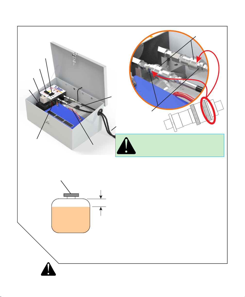
A: Check the 'quick couplers' in the Power Unit. If they are not
screwed together tight enough, built-in check valves will
not allow fluid to flow. See Page 13.
A: Check the fluid level. See Page 13.
Q: IS THE HYDRAULIC FLUID SAFE FOR THE FISH?
A:
We use a special low-toxicity hydraulic fluid that is safe
for the environment. This fluid is different than food-grade
oil. Only use Basta Boatlifts fluid in your hydraulic system.
Q: HOW DO I CHANGE THE HYDRAULIC FLUID?
A: Our fluid should not require replacement for a considerable
amount of time. If yours has been contaminated or the
hydraulic power unit has been replaced, visit our web site at
www.gobasta.com for detailed instructions.
POWER-UP
At power-up the remote fob function has a ten second delay.
Failure to wait for this ten seconds can make the wait time much
longer.
LIFT OPERATION
The remote fob is non-functional until it is enabled by
depressing the lower right unlock button momentarily. After
the initial ten second delay, depressing the unlock button enables
operation using the remote fob. The lockout is re-enabled after
60 seconds without a button press.
Lift operation using the fob is limited to 120 seconds of
continuous operation. If a longer cycle is needed it is necessary
to release and then re-depress the button.
LOW BATTERY LOCKOUT
This control incorporates a low voltage lockout which is
intended to protect the battery from abuse and over-discharge.
When the battery drops below the low battery threshold during
pump operation, further activation using the Fob is not allowed.
The battery needs to be checked prior to further operation. The
manual switches will allow the lift to operate if sufficient battery
power is present.
FOB PROGRAMMING
At initial power up there is a five second window when it is
possible to reprogram the receiver to enroll a remote fob. Up to
four fobs may be enrolled. If a fifth fob is enrolled, the first
enrolled fob will fall off the list.
To enroll a fob, turn off the power to the lift for fifteen or more
seconds. When power is turned back on press both the UP and
DOWN buttons on the fob simultaneously. This must be done
within the first five seconds after power is applied.
LIGHTING CIRCUIT
The lighting circuit is activated whenever the lift is operated. The
lights stay on for 2 minutes after the lift is operated
The lights may be manually turned on or off by depressing the
lower left button on the remote Fob. When manually enabled the
lights will automatically turn off after 4 minutes. This is prevents
accidental battery discharge.
STORAGE
Always leave the boat in the fully raised, Over-Center™
position with the power off.
FOR ASSISTANCE OR SERVICE:
Contact your local dealer or call 1 - 866 - GO BASTA
website: www.gobasta.com email: [email protected]
Your Basta Boatlift requires very little maintenance once installed.
Occasionally wipe the solar panel with a clean, damp cloth to preserve its charging performance.
Every 6 months, we recommend:
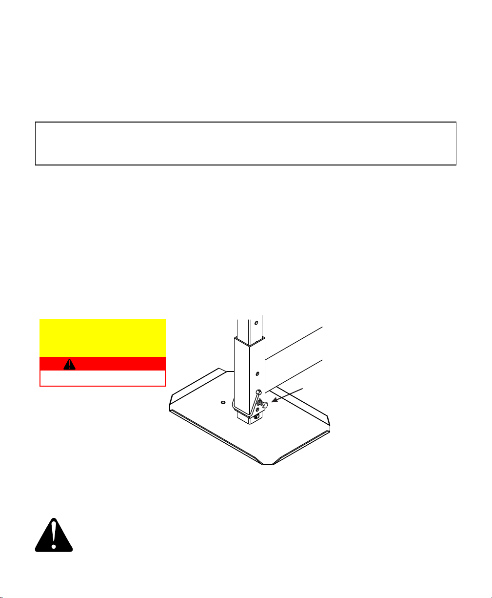
Inspect the lift frame for level and adjust the legs as necessary
Inspect the hoses, cylinders and fittings for leaks and wear - tighten as necessary.
Check the wire terminals for snugness and corrosion.
Check the hydraulic fluid and battery electrolyte levels (AGM batteries excluded):
The battery electrolyte in a flooded-cell battery should be slightly above the indicator ring in each cell.
Carefully add DISTILLED water if necessary. (Does not apply to AGM batteries.) Do not over-fill.
The hydraulic fluid level should be about one inch below the top of the reservoir with the lift DOWN.
DO NOT add fluid with the lift in the raised position!
Use only Basta Boatlifts biodegradable hydraulic fluid.
The battery in the key fob transmitter may be low. Replace it with a
new lithium CR2032. These are widely available at variety, hardware
and even grocery stores. Polarity is marked on the battery holder.
Other manuals for Over-Center 4.5k37
1
This manual suits for next models
1
Table of contents
Other Basta Boatlifts Lifting System manuals

Basta Boatlifts
Basta Boatlifts Over-Center 7k51 User manual

Basta Boatlifts
Basta Boatlifts Over-Center 4.5k37 User manual

Basta Boatlifts
Basta Boatlifts Over-Center 10k53 User manual

Basta Boatlifts
Basta Boatlifts Over-Center 12k64 User manual

Basta Boatlifts
Basta Boatlifts Over-Center 24k60 User manual

Basta Boatlifts
Basta Boatlifts 8k53 User manual

Basta Boatlifts
Basta Boatlifts Over-Center 18k59 User manual

Basta Boatlifts
Basta Boatlifts 2x2k50 User manual

Basta Boatlifts
Basta Boatlifts Over-Center 18k59 User manual

Basta Boatlifts
Basta Boatlifts 1.4k60 User manual