In general, the appliance should have ad-
equate ventilation for complete combustion
of gas, proper fl ueing and to maintain tem-
perature of immediate surroundings within
Remove the packaging accessories, includ-
ing the fi lms covering the chrome-plated and
stainless steel parts, from the cooker.
Position the cooker in a dry, convenient and
Any adjoining wall surface situated within
200mm from the edge of any hob burner
must be a suitable non-combustible material
for a height of 150mm for the entire length of
the hob. Any combustible construction above
the hotplate must be at least 600mm above
the top of the pan supports no construction
shall be within 450mm above the top of the
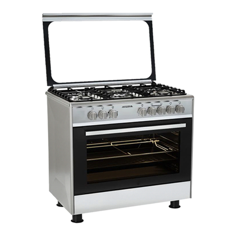
The cooker may be free-standing or between
two units the sides of which must withstand
f a combustible bench-top is situated within
200mm from the edge of any burner, it should
be 10mm or more below the cooker hob
Clip wire racks to sides of oven walls (Fig.
Slide shelves and trays on the guides as
CONNECTING TO THE GAS SUPPLY
Before connecting the cooker, check that it
is preset for the gas to be used. Otherwise,
make the conversion as described in the sec-
tion headed “Adapting to different gas types”.
The appliance is factory set for Natural gas.
The test point pressure should be adjusted
to 1.00kPa with the Semi Rapid and Rapid
burners operating at maximum. Ensure that
the gas regulator supplied with the cooker is
connected as close as practical to the gas
inlet. The gas connection is male 1/2 BSP
and is situated at the right hand rear of the
appliance, 605mm from the bottom of the
cooker ( without legs ) and 60mm fromm
- For ease of service, the cooker should be
connected with a fl exible hose.
Ensure the fl exible hose complies with AS/
NZS 1869 (AGA Approved), 10mm ID, class
B or D, between 1 - 1.2m long and is installed
in accordance with AS5601 for a high level
connection. The hose should not be subjected
to abrasion, kinking or permanent deformation
and should be able to be inspected along its
entire length. Unions compatible with the hose
fi ttings must be used and connections tested
for gas leaks. The fi xed consumer piping ou-
tlet should be at approximately the same hei-
ght as the cooker connection point, pointing
downwards and approximately 150mm to the
side of the cooker. The hose should be clear
of the fl oor when the cooker is in the installed
position. The installer must supply and install
a restraining device (typically chain) utilising
the anchor point provided for the anti tilt chain
closest to the gas connection point. This
restraining device must restrict the appliance
movement to no more than 80% of the hose
length to prevent strain on the hose connec-
tions when the cooker is pulled forward.
- Alternatively, the cooker can be connected
with rigid pipe as specifi ed in AS5601 table
- After installation, check that all connec-
- For operation with propane, check that the
gas pressure is as indicated on the name-
ADAPTING TO DIFFERENT TYPES OF
If the cooker is not already preset to oper-
ate with the type of gas available, it must be
converted. Proceed as follows:
- If the gas conversion kit is not supplied with
the appliance, contact the retailer/distribu-
tor to obtain the gas conversion kit.
