Bausch Datacom DinBox User manual

Reference manual
DinBox GSM/GPRS
modem

DinBox GSM/GPRS Reference manual – V1.0
Bausch Datacom NV
2
! CAUTION !
ELECTRIC SHOCK HAZARD IF COVER REMOVED
SERVICE BY QUALIFIED PERSONEL ONLY
Document History
Date Version Status Author Info
25/10/2004 V1.0 Preliminary Filip Lavaerts Creation

DinBox GSM/GPRS Reference manual – V1.0
Bausch Datacom NV
3
1. Introduction 5
2. Block Diagram 6
3. Specifications 8
3.1Housing 8
3.2 Connectors 8
3.3 Antenna Interface 9
3.4 Environmental conditions 10
3.5 Power Supply 10
3.6 GSM/GPRS module 10
4. SIM card 11
5. Ports and Connectors 12
5.1 Power Connection 12
5.2 Serial DTE Interface 13
5.3 I/O Connections 14
6.LEDIndicators 16
7. Watchdog functionality 17
8. Push Button 17
9. AT Command interface 18
A. EC-declaration of conformity 19
B. Antenna 20
C. RJ-45 Modular Jack 21
D. ESD Protection 22

DinBox GSM/GPRS Reference manual – V1.0
Bausch Datacom NV
4

DinBox GSM/GPRS Reference manual – V1.0
Bausch Datacom NV
5
1. Introduction
This manual is the reference book when setting up the DinBox GSM/GPRS modem for
your application. Because of the nature of this product and it's field of application, some
degree of technical background knowledge regarding the application and data-
communication is assumed.
The DinBox GSM/GPRS modem is a versatile communications device designed to
provide a very flexible data communication solution for an industrial environment. The
DinBox GSM/GPRS modem contains a number of options to accommodate different
communication speeds, power supplies and interfaces.
The DinBox GSM/GPRS is designed to transmit and receive data into a GSM data
and/or a GPRS channel.
But … there is more …
Information (serial data and/or input/output lines) can be transmitted/received via a
TCP/IP socket, e-mail, FTP, SMS or normal GSM data to and from remote host
systems.
GPRS connection can normally only be used if the DTE has TCP/IP capability to create
and send TCP/IP - PPP packages. Thanks to the embedded TCP/IP and the
implementation of a “Communication Control” processor the DinBox GSM/GPRS is, for
example, capable of opening/closing and maintaining a GPRS connection complete
independently of the DTE. Once the DinBox GSM/GPRS has opened the GPRS
connection the DTE can transmit and receive transparent ASCII data with a host
system.
Thanks to the 4 I/O lines it’s possible to read or change the status of control lines.
The DinBox GSM/GPRS is designed in a robust DIN rail housing with different power
supply options accepting a wide range of DC voltages.
Basically we have 5 DinBox GSM and 5 DinBox GPRS models available :
Standard versions
DinBox GSM
GSM modem
DinBox GPRS
GSM/GPRS modem with embedded TCP/IP
“Communication Control” processor versions
DinBox GSM or DinBox GPRS with …
•… 4 x I/O (TTL 3.7V)
•… 1 Input (Opto Coupler) – 1 output (Relais contact NO/NC)
•… 2 input (Opto Coupler)
•… 2 output (Relais contact NO/NC)

DinBox GSM/GPRS Reference manual – V1.0
Bausch Datacom NV
6
2. Block Diagram
The block diagram below details the location and interconnection of the different
functional units within the modem. The most important units are briefly described.
Power Supply
The power supply (DC) must be connected to the DinBox GSM/GPRS modem via a
terminal block with screw contacts. Make sure the voltage supplied to the modem is in
the range of the DinBox GSM/GPRS input voltage (see specifications for details on
voltage range). This input is protected against reversed polarity with a serial diode.
DTE Interface
The DinBox GSM/GPRS modem has a RS-232 interface (RJ-45) which can be
connected to a computer or similar DTE device via included RJ-45/DB-9 serial cable.
GSM/GPRS Modem
The DinBox GSM/GPRS modem has a Wavecom GSM/GPRS module on board.
Connection with the GSM dual band antenna is done via a standard SMA connector.
RS
-
232
10 - 50 Vdc
WatchDog “tick” LED
I/O TTL
DTE
Interface
Power
Supply
Watch
DOG
-
Control
Processor
-
Optional
- GSM
GPRS
Modem
TxD RxD DCD DTR GSM
Controle LED’s
LED on PCB (internal)
LED on Front

DinBox GSM/GPRS Reference manual – V1.0
Bausch Datacom NV
7
Watchdog circuit
A long-term watchdog circuit is implemented. The power supply of the Wavecom
GSM/GPRS module and the “Communication Control” processor will be disconnected
for a few seconds after the selected reset period.
If a part of the DinBox GSM/GPRS is ‘locked’ after e.g. an unexpected high ESD
discharge, surge pulse or an internal lock-up, this watchdog will always insure the
continuity of communication.
“Communication Control” Processor
This processor can monitor the whole communication process. This processor will also
control the 4 I/O lines and will perform the necessary action when input changes are
detected or when data is received to change output pins.
We have different basic “Communication Control” applications available :
DinBox GSM
-2 input – if input is changed -- SMS send
-2 output – SMS received – output will be changed
-1 input – SMS / 1 output SMS
DinBox GPRS
-1 input – to open a socket / 1 output – active when the socket is opened
-2 input – if input is changed – send predefined message in socket to a host
-2 output – receive predefined message in socket from a host – output will be
changed
The software for this “Communication Control” processor can be adapted for special
customer needs.
Please contact Bausch Datacom NV to have more information about all the possibilities
and existing implementations.

DinBox GSM/GPRS Reference manual – V1.0
Bausch Datacom NV
8
3. Specifications
3.1 Housing
Phoenix Contact EG22,5 ABS DIN rail housing
(EG22.5-G/ABS GN + EG22.5-A/ABS GN)
•22.5 mm 107.5 mm x 75 mm
•IP40
•Symmetrical DIN rail mounting according EN50 022
•Green color
Standard ABS
Acryl Butadiene Styrene – Tmax = 80 °C
Inflammability class acc. to UL 94 : HB
Optional PC (only on special request)
Polycarbonate – Tmax = 115 °C
metal DIN-rail clip
Inflammability class acc. to UL 94 : V0
3.2 Connectors
Antenna
SMA
Serial DTE
RJ
-
45
RXD
GSM
DCD
- +
Power
Supply
x x
Not
Used
I/O connections
4321
DTR
TXD
uP

DinBox GSM/GPRS Reference manual – V1.0
Bausch Datacom NV
9
Power Supply 4-pin header (MSTBO2.5/4-GR(L)-5.08)
pitch : 5.08 mm / Inom : 12 A / Unom : 250 V
& Not Used 4-pin plug (MVSTBW2.5/4-ST-5.08)
pitch : 5.08 mm / Inom : 12 A / Unom : 250 V / Max. conductor cross section, flexible : 2.5 mm²
I/O 4-pin header (MSTBO2.5/4-GR(L)-5.08)
pitch : 5.08 mm / Inom : 12 A / Unom : 250 V
Connections 4-pin plug (MVSTBW2.5/4-ST-5.08)
pitch : 5.08 mm / Inom : 12 A / Unom : 250 V / Max. conductor cross section, flexible : 2.5 mm²
Antenna Standard SMA connector
Serial DTE RJ-45 8x8 (Molex)
3.3 Antenne Interface
The GSM antenna can be mounted directly on the GSM modem via a cable, depending
on the application and the RF field at the local site. The antenna interface connector is
SMA (male).
Frequency TX: 890-915 MHz
RX: 935-960 MHz
Impedance 50 Ohms
VSWR TX: Max. 1.7:1 installed
RX: Max. 1.9:1 installed
Gain: > 1.5dB referenced to l/2 dipole
Maximum power 1W (cw)
2W peak; at ambient temperature of 55°C
Never use the DinBox GSM/GPRS modem without a
proper antenna attached!
CTS
RTS
RI
GND
DTR
TXD
RXD
DCD

DinBox GSM/GPRS Reference manual – V1.0
Bausch Datacom NV
10
3.4 Environmental conditions
Temperature in use -10°C / + 50°C
Humidity in use 10% - 75% (non condensing)
3.5 Power Supply
Input voltage range: 10 – 50 Vdc regulated
Typical power consumption : 350 mA
3.7 GSM/GPRS module
General specifications
•Dual-band 900/1800 MHz operation, designed to work with dual-band antennas.
•Maximum power output: 2 Watts
•3V SIM reader
•Asynchronous mode
•DTE interface with speeds up to 115.200 bps (RS-232 interface option)
•Flow control (RTS/CTS – XON/XOFF) and speed buffering
•Automatic format/speed (300 to 115,200 bps) sensing
•AT command set support
Data Features
GSM DATA :
•Data circuit asynchronous, transparent and non transparent up to 14400 bit/s
•Automatic fax group 3 (Class 1 and Class 2)
GPRS packet Data :
•GPRS Class 10
•Coding Schemes : SC1 to CS4
•PBCCH support
Message services
•Point to point (MT/MO) and cell broadcast
•EMS
Embedded IP
The following TCP/IP features and protocols are available :
PPP / ICMP / DNS / SMTP / POP3 / FTP / TCP socket

DinBox GSM/GPRS Reference manual – V1.0
Bausch Datacom NV
11
4. SIM card
Disconnect the mains power before opening the
DinBox GPRS modem!
Install a SIM card into the SIM card interface socket. Without a SIM card the DinBox
GSM/GPRS will communicate with the DTE but will not respond properly on all
commands.
The International Mobile Subscriber Identity (IMSI) is used for internal signaling and is
saved on the SIM (processor card). If the SIM is removed from the terminal, any existing
connections are cleared and further call setup is prevented with the exception:
emergency calls.
See the +CIMI command for more details.
Use the +CGSN command to view the Product Serial Number of the DinBox GPRS
modem.
How to install the SIM card:
1. Disconnect the power and DTE interface.
2. Open the DinBox GSM/GPRS housing.
3. The SIM cardholder is placed between the 2 PCB connectors onto the PCB.
4. Carefully slide the metal bracket to the ‘Open’ position.
5. Insert the SIM card into the SIM card holder (mind the correct direction).
6. Close the SIM card holder and slide the metal bracket into the ‘Lock’ position.
7. Close the DinBox GPRS enclosure.
8. Connect power and DTE interface.
See the +CPIN command for more info about entering the PIN number.

DinBox GSM/GPRS Reference manual – V1.0
Bausch Datacom NV
12
5. Ports and Connectors
Before you start the installation, take a moment to become more familiar with the
possible connections to and from the DinBox GSM/GPRS modem.
Disconnect the power before connecting or
disconnecting the power and/or DTE plugs !
5.1 Power Supply Connection
PIN
+ + DC
- - DC
Always disconnect the mains power before connecting or disconnecting the power.
Make sure the voltage supplied to the modem is in the range of the DinBox GSM/GPRS
power supply specification (see specifications for details on voltage range).
Antenna
SMA
Serial DTE
RJ
-
45
RXD
GSM
DCD
- +
Power
Supply
x x
Not
Used
I/O connections
432
1
DTR
TXD
uP

DinBox GSM/GPRS Reference manual – V1.0
Bausch Datacom NV
13
5.2 Serial DTE Interface
Only devices which are conform with the safety
regulations can be connected to the DTE port!
The DinBox PSTN is equipped with a RJ-45 (8x8) connector. This is the serial interface
of the modem.
A RJ-45 to a standard DB9 (female) cable is delivered with the DinBox GSM/GPRS
modem.
Pin
RJ45
Pin
DB9
V.24/V.28 I/O TEXT
CCITT DIN EIA
1 1 109 M5 DCD O Data carrier detect
2 2 104 D2 R D O Receive data
3 3 103 D1 T D I Transmit data
4 4 108/1
108/2
S1.1
S1.2
DTR I Data terminal ready
5 5 102 E2 GND --- Signal ground
- 6 107 M1 DSR O Data set ready
7 7 105 S2 RTS I Request to send
8 8 106 M2 CTS O Clear to send
6 9 125 M3 RI O Ring indicator
Output: from DCE (modem) to DTE (terminal)
Input: from DTE (terminal) to DCE (modem)
8 CTS
7 RTS
6 RI
5 GND
4 DTR
3 TXD
2 RXD
1 DCD

DinBox GSM/GPRS Reference manual – V1.0
Bausch Datacom NV
14
The DinBox GSM/GPRS modem will detect the DTE port speed (auto baud), number of
data bits and parity type from the "AT" header that precedes every command (in async
mode).
The commands +IPR and +ICF saves the baud rate, number of data bits, parity and
number of stop bits.
5.3 I/O connections
“Communication Control” processor versions are equipped with I/O. We provide I/O on
three possible levels ; TTL input and output, opto coupler input and relais contact
output.
Below you will find the different characteristics of the different I/O’s.
•TTL
The 4 TTL I/O lines are directly connected 4 port pins of the ATMEL AVR micro
controller and can be used as digital I/O or ADC inputs.
All connections are guarded with a Transil for ESD protection. See chapter D for more information.
Defined as Input :
(internally connected via 20Kohm pull-up to Vcc)
left open Æhigh input
grounded Ælow input
Symbol Parameter Condition Min Typ Max
VIL Input Low Voltage -0.5 V 0.7 V
VIH Input High Voltage 2.5 V 4 V
Defined as Output :
Vcc Æhigh output
GND Ælow output
Symbol Parameter Condition Min Typ Max
VOL Output Low Voltage IOL = 15 mA 0.6 V
VOH Output High Voltage IOH = -15 mA 3.0 V

DinBox GSM/GPRS Reference manual – V1.0
Bausch Datacom NV
15
•Opto Coupler Input
Input : 5 to 15 V (4 … 14 mA)
Other input specifications are optional possible.
•Relais Contact Output
Normal open contact (default)
Normal closed contact (optional)
Load Res. load (p.f. = 1) / Induct. load (p.f. = 0.4, L/R = 7 ms
Rated load 0.5 A at 125 Vac, 1 A at 24 Vdc
Max. operation voltage 125 Vac, 60 Vdc
Max. operation current 1 A
Vcc
To
p
rocesso
r
1 K
BAS16
- 1/3
+ 2/4
SFH6156-2
0 E
1/3
2/4 - From
p
rocessor
NO
NC

DinBox GSM/GPRS Reference manual – V1.0
Bausch Datacom NV
16
6. LED indicators
The InduBox GSM/GPRS has 6 LED indicators in front and 3 LED indicators onto the
PCB (internal).
Front panel :
GSM GSM Network
service DCE LED off: no service
Pulse 80% on/ 20% off: emergency
service
Pulse 20% on / 80 % off: limited
availability
LED on: full service
TXD Transmit Data DTE ÆDCE Reflects the state of the TXD signal
RXD Receive Data DCE ÆDTE Reflects the state of the RXD signal
DTR Data Terminal Ready DTE ÆDCE Reflects the state of the DTR signal
DCD Data Carrier Detect DCE ÆDTE Reflects the state of the DCD signal
µP (PD6) (*)
Onto PCB (internal) :
µP (PB7) (*)
µP (PB6) (*)
WD Watchdog “Tick” - Reflects the state of the Watchdog
(*) “Communication control” processor (µP - micro processor) LED indicators functions
are defined/described in the separate user manuals depending on the application.
IMEI CODE
SIM
µ
P
(
PB6
)
µ
P
(
PB7
)
WD LED

DinBox GSM/GPRS Reference manual – V1.0
Bausch Datacom NV
17
7. Watchdog functionality
To prevent a “total lock-up” of the DinBox GSM/GPRS a long term watchdog is
implemented. This function is created with a separate RISC micro controller. The micro
controller itself is guarded with it’s own internal watchdog (+/- 1 second refresh / WD
LED flash).
The power supply to the “Communication Control” processor and the modem module
will be disconnected for a few seconds after +/- 24 hour IF the modem is NOT
connected (inactive DCD signal).
If the reset period is ended and the modem is connected to a remote host (active DCD
signal) the reset will not be conducted.
If the reset period is ended and the watchdog already past a reset, because of an active
DCD signal, the reset will be conducted after +/- 10 minutes !
Otherwise, if the DinBox GSM/GPRS is “locked-up” with an active DCD signal the
watchdog will never be able to reset the WAN module.
8. Push button
The DinBox GSM/GPRS modem has a simple push button (switch) onto the PCB.
This switch can be used to start-up the DinBox GSM/GPRS without the “Communication
Control” processor. This function is necessary during first-time configuration of the
DinBox GSM/GPRS or for manual communication tests and debugging purposes.
IMEI CODE
SIM
Switch

DinBox GSM/GPRS Reference manual – V1.0
Bausch Datacom NV
18
9. AT Command interface
The operating functions of the GSM Data Modem are implemented as AT commands
and responses and are available via the serial DTE interface.
The DinBox GSM/GPRS is based on the Wavecom Wismo Q2403 module.
The original Wavecom manuals are available onto the CD-ROM.
Two manuals are available :
AT Commands Interface Guide.
This manual describes the AT-commands based messages exchanged between an
application and the DinBox GPRS modem in order to manage GSM related events or
services.
AT Commands Interface Guide for IP Connectivity.
(DinBox GPRS version only)
This manual describes the AT-commands dedicated to IP connectivity.

DinBox GSM/GPRS Reference manual – V1.0
Bausch Datacom NV
19
A. EC-Declaration of conformity

DinBox GSM/GPRS Reference manual – V1.0
Bausch Datacom NV
20
B. Antenna
Dual band GSM antenna
Frequency: 880 - 1880 MHz
Gain: 0 dB
RG 174 cable 250 cm with
FME plug (female)
Table of contents
Other Bausch Datacom Modem manuals
Bausch Datacom
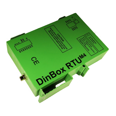
Bausch Datacom DinBox RTU M4 User manual
Bausch Datacom
Bausch Datacom Vega 56 PC2 User manual
Bausch Datacom
Bausch Datacom Proxima ISDN Lite User manual
Bausch Datacom
Bausch Datacom InduBox GSM M4 Instruction sheet
Bausch Datacom
Bausch Datacom DinBox GSM M4 User manual
Bausch Datacom
Bausch Datacom DinBox PSTN User manual
Bausch Datacom
Bausch Datacom InduBox PSTN III Instruction sheet
