Bausch Datacom InduBox GSM M4 Instruction sheet

Installation & Configuration manual
InduBox GSM M4
V1.1

! CAUTIO !
ELECTRIC SHOCK HAZARD IF COVER REMOVED
SERVICE BY QUALIFIED PERSO EL O LY
Document History
Date Version Auteur
29/01/18 V1.0 Preliminary Filip Lavaerts Creation / V1.0 InduBox SM M4 hardware manual
28/05/18 V1.1 Preliminary Filip Lavaerts Adding/edit Wouter’s info about configuration

Table of Contents
1. Introduction
2. Block Diagram
3. Specifications
Housing and Connectors
Environmental conditions
Power Supply Specifications
4. SIM Card
5. Ports and Connectors
Mains Power Connection
Isolated DTE Interfaces
Isolated RS-232 connection
Isolated RS-485 connection
Pin 1
Ethernet interface
Antenna interface
Non isolated DTE interface
6. LED Indicators
7. InduBox GSM M4 HTML GUI Configuration
A. EC-declaration of conformity
B. Basic Dimensions

Serial flow as used in this manual :
DCEDTE
TxD
RxD
DTR
DCD
RTS
CTS
RI
DSR
G D
Modem
InduBox GSM M4
Communication
device
PC
POS
PLC
Application
I
OUT
Data
Terminal
Equipment
Data
Communication
Equipment

1. Introduction
This manual is the reference when setting up the InduBox SM M4 modem for your
application. Because of the nature of this product and its field of application, some
degree of technical background knowledge regarding the application and data-
communication is assumed.
The InduBox SM M4 modem is a versatile communication device designed to provide
a flexible data communication solution for an industrial environment. The InduBox SM
M4 modem contains a number of options to accommodate different communication
speeds, power supplies and interfaces.
This modem has an extended TCP/IP stack implementation, and is able to connect non-
IP devices to an IP network over an Ethernet or SM link.
The main specifications of the InduBox SM M4 are :
InduBox wall mountable housing
Configuration, setup and monitoring via UI / HTML pages
8 x status LEDs
10/100 Mb Ethernet interface
full RS-232 DCE serial interface
galvanic isolated 2-wire RS-485 serial interface
galvanic isolated 3-wire RS-232 serial interface
1 x passive galvanic isolated digital input
Sierra Wireless HLx SM module
SIM card holder internally
FME antenna connector
powerful Cortex M4 processor
2Mb EEPROM [262.144*8 bit]
64KB FRAM [8.192*8 bit]
Thanks to the powerful Cortex M4 processor it's possible to add IP basic routing and/or
standard RTU protocols like IEC60870-104 or other customer specific protocol
demands.

2. Block Diagram
The block diagram below details the location and interconnection of the different
functional units within the modem. The most important units are briefly described.
AC/DC power supply
The mains supply (ac) must be connected to the InduBox SM M4 modem via a 2 pin
terminal block with screw contacts. Make sure the voltage supplied to the modem is in
the range of the InduBox SM M4 input voltage (see specifications for details on
voltage range).
Configuration Interface
The InduBox SM M4 modem has one complete (TxD, RxD, DCD, DTR, RTS, CTS, RI
and ND) RS-232 interface. This RS-232 interface is not isolated and can be used to
configure and/or debug tracing. This interface has a RJ-45 connector.
Ethernet Interface
The InduBox SM M4 modem has one standard 10/100 Mbit/s ethernet LAN interface.
This interface can be used to configure the modem via the HTML UI.
Power
Supply
Power
Input
ETH
RS-232
RS-485
LAN WAN
PPPos
SM
2/3/4
AT
Command
parser
... TCP/IP
Server
IP stack
PPPoS
STM32 F4 – CORTEX M4
DI
8x status LED
RS-232

Isolated DTE interfaces
The InduBox SM M4 has 2 galvanically isolated serial interfaces :
3- wire RS-232 (RxD, TxD, G D’)
3- wire RS-485 (A, B, G D’)
Those interfaces are galvanically separated and can be used to connect a serial device.
Both interface connections are done through one RJ-45 connector.
The V' - pin can be used for external reset (V') or for powering (100 mA Imax) an
external device (+5V'), selectable via a JP6.
8x Status LED’s
The InduBox SM M4 has 8 status LED’s.
SM module
The InduBox SM M4 is using a Sierra Wireless CF3 footprint SM module as WAN
device. Thanks to the Sierra Wireless CF3 HL footprint for the WAN module, the InduBox
SM M4 offers the flexibility to easily migrate communication technologies, thus making
it future proof. Depending on the application, the modem can be provided with standard
3 PP cellular 2 PRS, 3 UMTS, 4 LTE, LPWA (low power wide area), LTE Cat-M1
or NB-IoT. LPWA with 3 PP 2 PRS fallback is also possible. Most modules are
available for global or NAM, EMEA and APAC only regions.
The following options are possible (Q3 2018) :
3 PP
HL6528 – quad band SM/ PRS & SM Data
HL6528RD – quad band SM/ PRS
HL8518 – dual band HSPA, SM/ PRS/ED E
HL8548 – quad band HSPA, SM/ PRS/ED E
HL7690 – FDE band LTE Cat-1 (*)
HL7692 – FDE band LTE Cat-1 with dual band SM/ PRS/ED E fallback (*)
LPWA
HL7800 – LTE Cat-M1, NB-IoT
HL7802 – LTE Cat-M1, NB-IoT with dual band SM/ PRS fallback
(*) only with 1-SISO antenna connection

3. Specifications
3.1 Housing and Connectors
Housing: Bausch InduBox IP51 housing
bottom enclosure and sealable connector cover
ABS with self-extinguishing V0 additive
transparent cover
polycarbonate + self-extinguishing V1
dimensions with connector cover: 180 x 108 x 71 mm
dimensions without connector cover: 145 x 108 x 71 mm
Connectors: Mains plug and connector (terminal block screw connector)
pitch 5.08 mm
maximum wiring section 2.5 mm2
Female RJ-45 connectors (RS-232, RS-485)
RJ-45 Ethernet connector
AMP 50 Ohm FME antenna connector
3.2 Environmental conditions
Temperature in use -25°C / + 55°C
Humidity in use 10% - 75% (non condensing)
3.3 Power Supply Specifications
Input voltage range: 90 – 253 Vac
Input frequency: 47 – 63 Hz
Power: 1,8 Widle 5 Wmax
Disconnect the mains power before opening the
InduBox GSM M4 modem!

4. SIM Card
Install a SIM card into the SIM card interface socket. Without a SIM card the InduBox
SM M4 will not be able to communicate over the WAN interface.
How to install the SIM card:
1. Disconnect the mains power and DTE interface.
2. Open the InduBox SM M4 enclosure.
3. The SIM cardholder is placed in the upper right corner onto the PCB.
4. Slide the upper part to the LEFT position.
5. Rotate the SIM card holder upper part to the upright position.
6. Insert the SIM card into the upper part of the card holder.
7. Rotate back and close the upper part of the SIM cardholder
8. Finally slide the upper part to the right (LOCK) position.
9. Close the InduBox SM M4 enclosure.
10. Connect mains power and DTE interface.
Power Supply GSM
module
Mains
Serial
Antenna
Ethernet
SIM
L1
L2
GSM
TXD
RXD
DTR
RI
DCD
CO 3
DC
H1
JP1
JP2
Term
JP3JP6
JP7 JP8
2
4
Meter
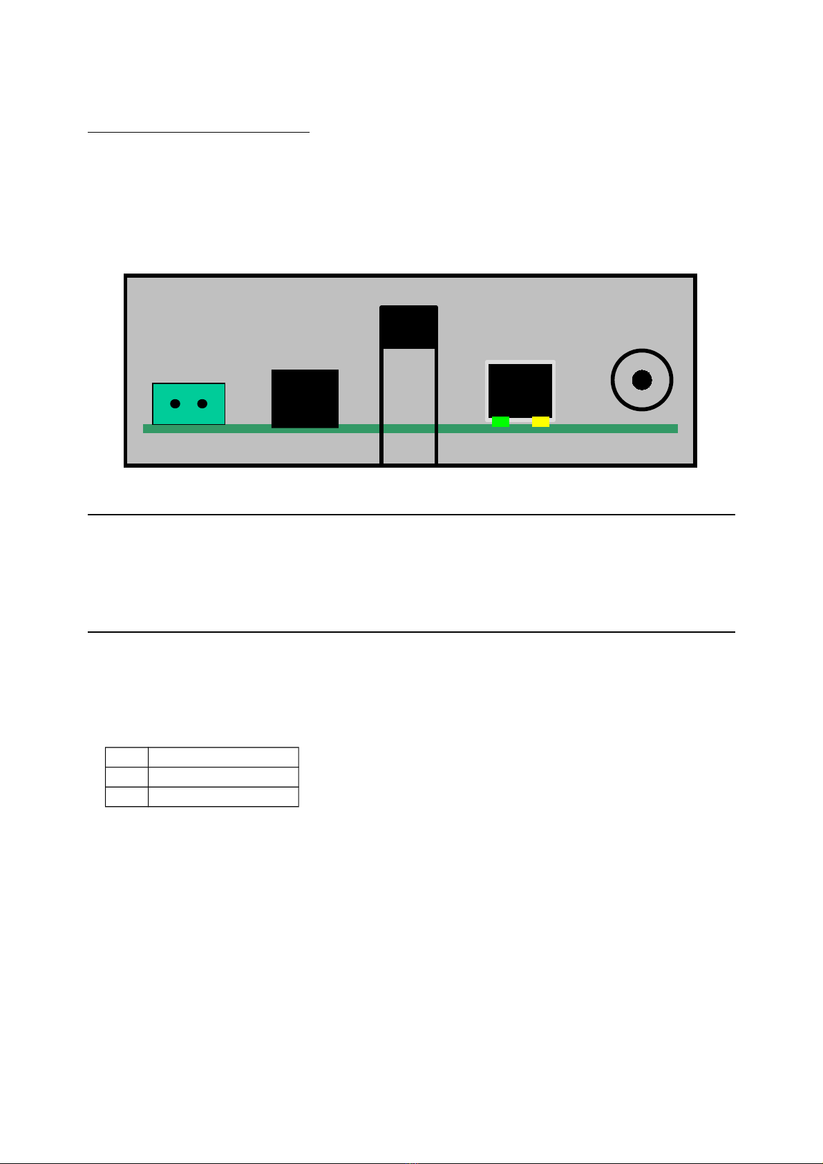
5. Ports and Connectors
Before you start the installation, take a moment to become more familiar with the
possible connections to and from the InduBox SM M4 modem.
The InduBox SM M4 has three types of connectors; a mains terminal block screw
connector, two RJ-45 connectors and one FME connector.
Disconnect the mains power before connecting or
disconnecting the power and/or DTE plugs !
5.1 Mains Power Connection
PI
1 N
2 L1
Always disconnect the mains power before connecting or disconnecting the power plug.
Make sure the voltage supplied to the modem is within range of the InduBox SM M4
input voltage (see specifications for details on voltage range).
There is no fuse or circuit breaker built-in to the InduBox SM M4, this must be added
externally.
When the InduBox GSM M4 modem is connected via a standard mains plug, the
used mains socket must be directly accessible and easy reachable.
SERIAL Ethernet A T
Mains
L1

5.2 Isolated Serial DTE Interfaces
The isolated serial interfaces are galvanically separated from the main circuits of the
InduBox SM M4 ; the RxD and TxD lines are separated via an OptoCoupler, a second
5 Vdc power supply is created via an additional DC/DC convertor.
Two isolated serial interfaces are possible on the same RJ-45 connector :
RS-232 3-wire & '+V'
RS-485 3-wire & '+V'
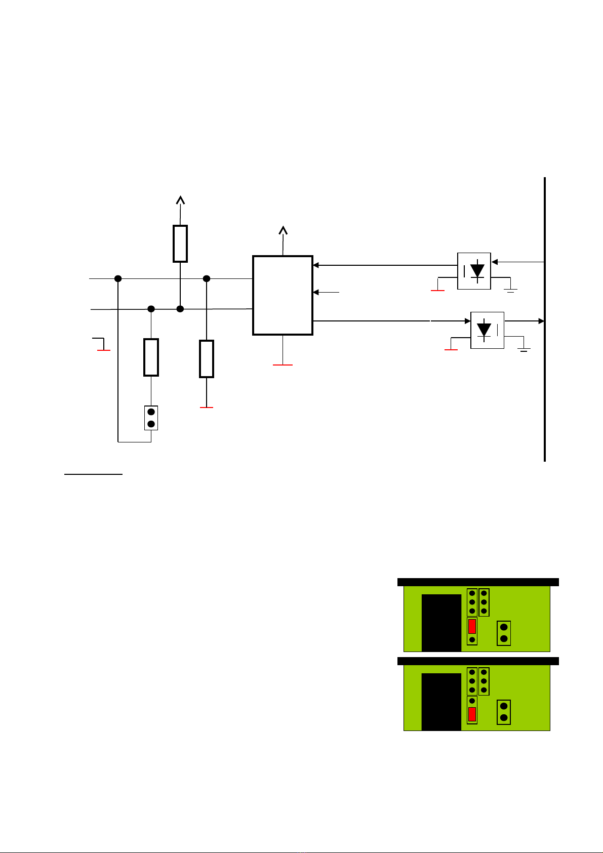
5.2.1 Isolated RS-232 interface
To be used when a RS-232 device must be connected to the InduBox SM M4.
•Jumper settings
JP7 & JP8 on position ‘2’
•Connection
PI RS-232 Direction Level
1 +V - - 5~25 Vdc in OR +5V' out (JP6)
2 - - - -
3 - - - -
4 - RXD DCE DTE V.28
5 - TXD DTE DCE V.28
6 - ND' - V.28
7 - - - -
8 - - - -
Ethernet A T
Mains
L1
Serial Interface
RJ-45 8 contacts
1 ………. 8
Serial
Term
JP3JP6
JP7 JP8
2
4
Meter

•Schematic overview
5.2.2 Isolated RS-485 interface
To be used when a RS-232 device must be connected to the InduBox SM M4.
•Jumper settings
JP7 & JP8 on position ‘4’
•Connection
PI RS-485 Level
1 +V - 5~25 Vdc in OR +5V' out (JP6)
2 - B V.11
3 - - -
4 - A V.11
5 - A V.11
6 - ND' -
7 - B V.11
8 - - -
UART
5V5V’
TxD
RxD
5V’
RXD
TXD
ND’
TTL/V.10
Level
Shift
Ethernet A T
Mains
L1
Serial Interface
RJ-45 8 contacts
1 ………. 8
Serial
Term
JP3JP6
JP7 JP8
2
4
Meter
JP3 “Term” open no 120 ohm termination between A and B
“Term” closed 120 ohm termination between A and B
•Schematic overview
5.2.3 Pin 1
Pin 1 of the RJ-45 connector can have 3 functions, available in the RS-485 and RS-232
configurations.
•No connection (default)
When JP6 is not placed, pin1 is not connected.
•5Vdc outgoing
To have 5Vdc (maximum 100mA) onto pin 1.
•Input (reset) function
Pin 1 is connected to a DI (digital input via an
optocoupler). An input voltage of 5 to 25Vdc is
needed to activate the DI.
Depending on the firmware this can for example
reset the InduBox SM M4.
A
B
receiver
transmitter
DE
120 E
JP3
UART
5V’
B
A
ND'
RxD
TxD
5V’
560 E
560 E
Serial
Term
JP3JP6
JP7 JP8
2
4
Meter
Serial
Term
JP3JP6
JP7 JP8
2
4
Meter

5.3 Ethernet interface
This 10/100 Mbit/s LAN interface is primarily used to configure the InduBox SM M4.
Default IP address is 192.168.1.44 / 255.255.255.0.
HTML is available on standard port 80.
5.4 Antenna interface
The SM antenna must be connected on the SM modem via a cable, depending on
the application and the SM RF field strength at the site. The antenna interface
connector is FME (male).
ever use the InduBox GSM M4 modem without a
proper antenna attached!

5.5 on isolated DTE Interface
This interface can be used to connect a standard serial device or to configure or debug
the InduBox SM M4. This interface is accessible via a RJ-45 8-pin connector, is not
galvanically isolated and has all standard V.24 interface lines. A RJ-45 to a standard
female DB-9 connector cable is available.
PI V.24 Description Direction Level
1 DCD Data Carrier Detect DCE DTE V.28
2 RXD Receive Data DCE DTE V.28
3 TXD Transmit Data DTE DCE V.28
4 DTR Data Terminal Ready DTE DCE V.28
5 ND round - -
6 RI Ring Indicator DCE DTE V.28
7 RTS Request to Send DTE DCE V.28
8 CTS Clear to Send DCE DTE V.28
Power Supply GSM
module
Mains
Serial
Antenna
Ethernet
SIM
L1
L2
GSM
TXD
RXD
DTR
RI
DCD
CO 3
DC
H1
JP1
JP2
Term
JP3JP6
JP7 JP8
2
4
Meter
Serial Interface
RJ-45 8 contacts
8 ………. 1

6. LED Indicators
There are 8 LED’s located onto the
InduBox SM M4 modem printed circuit.
L1 green RSSI: Received
Signal Strength,
indicating the
received power level.
A higher number
indicates a better
connection.
DCE Always ON : +CSQ==99
1 periodical flash: +CSQ >10
2 periodical flash: +CSQ 10-14
3 periodical flash: +CSQ 15-19
4 periodical flash: +CSQ 19-23 :
5 periodical flash: +CSQ >23
L2 green WAN TCP/IP
connection
DCE OFF: No connection
Slow flash: WAN IP received
ON: TCP socket open
SM yellow SM Network
service
DCE ON: not registered on the network
Slow flash (2 s. OFF):
registered on the network
Quick flash (600 ms OFF):
communication in progress
TXD red Transmit Data DTE DCE TXD signal of the SM module
RXD red Receive Data DCE DTE RXD signal of the SM module
DTR red Data Terminal Ready DTE DCE DTR signal of the SM module
DCD red Data Carrier Detect DCE DTE DCD signal of the SM module
RI red Ring Indicator DCE DTE RI signal of the SM module
DC green Isolated 5Vdc power
supply
- OFF: no voltage present
ON: voltage present

7. InduBox GSM M4 HTML GUI Configuration
Configuration of the InduBox SM M4 can be done through a UI via HTML.
The default ip address of the modem is 192.168.1.44.
Username : admin
Password : password
Click on “login” to enter the configuration pages of the modem.
To make changes, always save the change at the bottom of the page and reboot
the modem before the change is executed.

Status
Displays the most important configuration.
General
System info
•Software Version
•Uptime: time passed after power-on or reset of the modem
LAN - Info about the local Ethernet interface:
•IP Address
•Netmask
•MAC Address
WAN - Info about the WAN interface, which is the connection over the mobile network:
•SIM Access: pin code of the installed SIM card.
•Network band indicator: frequency band of the mobile connection.
•Operator selection: Network operator to which the modem is connected.
•RSSI: Received Signal Strength, indicating the received power level. A higher
number indicates a better connection.
•IP Address: received/used WAN IP address
•Netmask
•Uptime: time passed after getting a WAN IP address

Configuration
To change the configuration: change the parameter, press Save Changes on the same
page and Reboot the module.
LAN
Configuration of the local Ethernet interface.
IP
•IP Address: Set the IP address of the local Ethernet interface
•Subnet Mask
•Default gateway, enter 0.0.0.0 when not in use
•DNS1, enter 0.0.0.0 when not in use
•DNS2, enter 0.0.0.0 when not in use
DHCP
•Client: Turn on to get an IP address from a DHCP server, off for static ip.
Dynamic IP not visible on trace/browser

Serial
configuration of the serial port.
Configuration Interface RS-232 - Set the serial parameters of the RS-232 configuration
interface. These parameters should match the parameters of the connected device.
•Baud rate
•Data Bits
•Parity
•Stop Bits
•Flow control
Isolated interface - Set the serial parameters of the isolated RS-232/RS-485 interface.
Should be the same as for the device connected.
•Type: this isolated interface can be hardware configured as an RS-232 (3-wire) or
RS-485 (2-wire) interface. See above JP7 & JP8.
•Baudrate
•Data Bits
•Parity
•Stop Bits
•Driver Enable Delay: Delay between sending the last character and disabling the
RS-485 transceiver.
Table of contents
Other Bausch Datacom Modem manuals

Bausch Datacom
Bausch Datacom InduBox PSTN III Instruction sheet

Bausch Datacom
Bausch Datacom DinBox RTU M4 User manual

Bausch Datacom
Bausch Datacom DinBox GSM M4 User manual

Bausch Datacom
Bausch Datacom Vega 56 PC2 User manual

Bausch Datacom
Bausch Datacom DinBox User manual

Bausch Datacom
Bausch Datacom DinBox PSTN User manual

Bausch Datacom
Bausch Datacom Proxima ISDN Lite User manual


