Bausch Datacom DinBox GSM M4 User manual

Reference Manual for
DinBox GSM M4
V1.0a
Bausch Datacom NV Tiensesteenweg 6 B-3360 Korbeek-Lo Belgium +32 16 461288

! CAUTION !
ELECTRIC SHOCK HAZARD IF COVER REMOVED
SERVICE BY QUALIFIED PERSONEL ONLY
Bausch Datacom nv 2DinBox GSM M4 V1.0a

1. Introduction
2. Block Diagram
3. S ecifications
3.1 Environmental
3.2 Housing
3.3 Power su ly
3.4 GSM Module
3.5 Ins and outs
3.5.1 Power
3.5.2 Serial Interfaces
3.5.3 Ethernet
3.5.4 Digital In ut
3.5.5 Digital Out ut
3.5.6 SIM Card Reader
3.5.7 GSM Antenna
4. LED Indicators
5. Configuration & Setu
Bausch Datacom nv 3DinBox GSM M4 V1.0a

Bausch Datacom nv 4DinBox GSM M4 V1.0a

1. Introduction
This manual is the reference guide when setting u the "DinBox GSM M4" modem.
This modem has an Ethernet, a RS-232 and a RS-485 interface, 1 digital out ut and 1
digital in ut. It has a built-in ower su ly and an integrated GSM, GPRS, 3G or 4G
module.
U to 5 different ower su ly o tions are ossible to meet all su ly demands.
This modem has an extended TCP/IP stack im lementation, and is able to connect non-
IP devices to an IP network over an Ethernet or GSM/GPRS link.
Thanks to the owerful Cortex M4 rocessor it's ossible to add IP routing and/or
standard RTU rotocols like IEC60870-104 or other customer s ecific rotocol
demands.
The main s ecifications of the “DinBox GSM M4” are:
DIN rail mountable housing
Configuration, setu and monitoring via HTML ages
10 x status LEDs
10/100 Mb Ethernet interface
full RS-232 DCE serial interface
galvanic isolated 2/4-wire RS-485 serial interface
1 x assive galvanic isolated digital in ut
1 x galvanic isolated digital out ut
Sierra Wireless HL6 2G GSM/GPRS module (o tionally 3G or 4G)
SIM card holder (SIM card externally accessible)
SMA antenna connector
owerful Cortex M4 rocessor
2Mb EEPROM [262.144*8 bit]
64Kv FRAM [8.192*8 bit]
Because of the nature of this product and it's field of application, some degree of
technical background knowledge regarding the application and data-
communication is assumed.
Bausch Datacom nv DinBox GSM M4 V1.0a

Bausch Datacom nv 6DinBox GSM M4 V1.0a

2. Block Diagram
The block diagram below details the interconnection of the different functional units
within the "DinBox GSM M4".
Power Su ly
The "DinBox GSM M4" has 5 different ower su ly o tions. Before connecting ower
lease check carefully that the su lied voltage and the wire connection is correct.
PS1 o tion AC isolated 85 – 264 Vac / 100 – 370 Vdc
PS2 o tion DC isolated 18 – 75 Vdc
PS3 o tion DC isolated 9 – 36 Vdc
PS4 o tion DC non-isolated 9 – 57 Vdc
PS5 o tion DC non-isolated 10 – 15 Vdc
There is NO built-in fuse. Power must be rovided via a ro er fuse.
More information about the wire connection, see following cha ters.
Configuration interface
All configuration, setu and monitoring is done via IP - HTML via the Ethernet interface.
Bausch Datacom nv 7DinBox GSM M4 V1.0a
Power
Su ly
Power
In ut
ETH
RS-232
RS-485
LAN WAN
PPPos
GSM
2/3/4G
AT
Command
arser
Praxis
SNMP
client
TCP/IP
Server
IP stack
PPPoS
STM32 F4 – CORTEX M4
DI
DO
10x status LED

GSM Module
The "DinBox GSM M4" has a built-in Sierra Wireless HL6 2G GSM/GPRS module.
O tionally a 3G or 4G GSM module is ossible.
This module will be used to transfer data from/to the CTU or host system. The GSM
module needs a SIM card. The PIN code request can be enabled or disabled. A
standard SMA connection is rovided to connect an external GSM antenna.
Cortex M4 rocessor
The core of the “DinBox GSM M4” is the owerful Cortex M4 rocessor. This rocessor
will/can control the following tasks;
-TCP/IP stack
-RTC (real time clock)
-communication with the Sierra Wireless GSM/GPRS module
-serial RS-485 / RS-232 communication
-calculations on measured or received data
-scan DI changes
-set DO
-write and read data in/from the non-volatile FRAM and/or EEPROM memory
-….
IO
This RTU has 1 DI and 1 DO
1 x DI - galvanic isolated (o tocou ler)
- assive in ut (needs 9 – 25Vdc to activate)
1 x DO - galvanic isolated (o tomos ‘solid state’ relay)
FRAM
The "DinBox GSM M4" has one FRAM (ferro electric RAM) of 64 Kbit (8.192 x 8 bits).
This non-volatile memory can/will be used to store the configuration, measured data and
log information.
EEPROM
The "DinBox GSM M4" has one EEPROM (electrical erasable rogrammable ROM) of 2
Mbit (262.144 x 8 bits). This non-volatile memory can/will be used to store the rogram
code during a firmware u date.
See next cha ter for more technical details.
Bausch Datacom nv 8DinBox GSM M4 V1.0a

3. S ecifications
3.1 Environmental
•O eration tem erature range : -30 ~ +70 °C (*)
(*) The embedded GSM/GPRS module remains fully functional during
and after this tem erature ex osure and shall meet the minimum
requirements of 3GPPP or a ro riate standards.
•Storage tem erature range : -40 ~ +85 °C
•Relative humidity (non condensing) : 5 ~ 95 %
•IP class : IP3x
3.2 Housing
The "DinBox GSM M4" is enclosed into a Bernic Series 1570 housing.
This housing is 9 modules wide and has a DIN rail sna slot for easy DIN rail mounting.
dimensions 157 mm x 86 mm x 58 mm
self-extinguishing according to UL94-V0
maximum tem erature 100 °C
color black (base art) and grey (to art)
Bausch Datacom nv 9DinBox GSM M4 V1.0a

Bausch Datacom nv 10 DinBox GSM M4 V1.0a
1 26
27
62,5 62,5
62,5 dia 6,5
64,7
48,5
[16,2][17,4]
21,8
4,4
40,5
12,3
5
11,4
14,2
12
4,2
[17,3]
605 - 4 in
5mm itch
15
10
605 - 4 in
5mm itch
605 - 2 in
5mm itch
605 - 2 in
5mm itch
SIM card
holder standard
RJ-45
SMA
antenne
10x LED
conductor
3 mm
shielded
RJ-45
Ethernet
with 2 LED's
13
19
6
66
6
dia 3,x ?

3.3 Power Supply
The "DinBox GSM M4" has 5 ower o tions. Please verify carefully that your roduct
has the correct ower su ly o tion BEFORE connecting the ower voltage.
PS1 o tion AC isolated 85 – 264 Vac / 100 – 370 Vdc
In ut voltage range 85 – 264 Vac / 100 – 370 Vdc
Frequency range 47 ~ 440 Hz
Standards EMC, UL1950, TUV EN60950
Withstand voltage 4.000 Vac / 1 min
recommended fuse 1 A / 250 V slow blow
Idle ower consum tion tbd W
Max ower consum tion tbd W
PS2 o tion DC isolated 18 – 75 Vdc
In ut voltage range 18 – 75 Vdc
Standards EMC, UL, TUV EN60950
Withstand voltage 3000 Vdc / 1 min
Idle ower consum tion tbd mA
Max ower consum tion tbd mA
PS3 o tion DC isolated 9 – 36 Vdc
In ut voltage range 9 – 36 Vdc
Standards EMC, UL, TUV EN60950
Withstand voltage 3000 Vdc / 1 min
Idle ower consum tion tbd mA
Max ower consum tion tbd mA
PS4 o tion DC non-isolated 9 – 57 Vdc
In ut voltage range 9 – 57 Vdc
Idle ower consum tion tbd mA
Max ower consum tion tbd mA
PS5 o tion DC non-isolated 10 – 15 Vdc
In ut voltage range 10 – 15 Vdc
Idle ower consum tion tbd mA
Max ower consum tion tbd mA
tbd → to be defined (15/04/2016)
There is NO built-in fuse. Power must be rovided via a ro er fuse.
More information about the wire connection, see following cha ters.
Bausch Datacom nv 11 DinBox GSM M4 V1.0a

3.4 GSM module
The “DinBox GSM M4” has a built-in state-of-art Sierra Wireless quad band GSM/GPRS
module. Currently [15/04/2016] two o tions are ossible :
HL6528 (2G/GPRS) or HL8548 (3G).
HL6528 (2G/GPRS) features:
GSM Output Power Class 4 (2 W) for GSM 850 and E-GSM 900
Class 1 (1 W) for DCS 1800 and PCS 1900
GPRS Quad-band GSM 850/E-GSM 900/DCS 1800/PCS 1900
GPRS Multi-slot class 10
R99 su ort
PBCCH su ort
Coding schemes: CS1 to CS4
UIM Interface 1.8V/3.0V su ort for UIM1
Su orts UIM a lication tool kit with roactive UIM commands
Application Interface Full set of AT for GSM/GPRS including GSM 07.07 and 07.05 AT command sets
Com rehensive set of dedicated AT commands for M2M a lications
SMS SMS class 0,1 and 2
SMS MT, MO
SMS storage into UIM card or Flash memory
Concatenation of MT SMS
HL8548 (3G) features:
Power RF Band Transmit band (Tx) Receive band (Rx) Maximum Output Power
UMTS B1 1922 to1978 MHz 2112 to 2168 MHz 23 dBm (+/- 2dBm) Class 3bis
UMTS B2 1852 to 1908 MHz 1932 to 1988 MHz 23 dBm (+/- 2dBm) Class 3bis
UMTS B5 826 to 847 MHz 871 to 892 MHz 23 dBm (+/- 2dBm) Class 3bis
UMTS B6 832 to 838 MHz 877 to 883 MHz 23 dBm (+/- 2dBm) Class 3bis
UMTS B8 882 to 913 MHz 927 to 958 MHz 23 dBm (+/- 2dBm) Class 3bis
UMTS B19 832.4 to 842.6 MHz 877.4 to 887.6 MHz
GSM 850 824 to 849 MHz 869 to 894 MHz 2 Watts GSM, GPRS and EDGE
E-GSM 900 880 to 915 MHz 925 to 960 MHz 2 Watts GSM, GPRS and EDGE
DCS 1800 1710 to 1785 MHz 1805 to 1880 MHz 1 Watt GSM, GPRS and EDGE
PCS 1900 1850 to 1910 MHz 1930 to 1990 MHz 1 Watt GSM, GPRS and EDGE
UIM interface 1.8V/3V su ort
Conforms with ETSI UICC S ecifications.
Su orts SIM a lication tool kit with roactive SIM commands
Application interface AT interface – 3GPP 27.007 standard, lus ro rietary extended AT commands
Protocol Stack Dual-mode UMTS (WCDMA) / HSDPA / HSUPA / EDGE / GPRS / GSM o eration
GSM/GPRS/EDGE
WCDMA
HSDPA (High S eed Downlink Packet Access)
HSUPA (High S eed U link Packet Access)
HSPA+ (Evolved High S eed Packet Access)
Bausch Datacom nv 12 DinBox GSM M4 V1.0a

SMS SMS MO and MT
CS and PS su ort
SMS saving to SIM card or ME storage
SMS reading from SIM card or ME storage
SMS sorting
SMS concatenation
SMS Status Re ort
SMS re lacement su ort
SMS storing rules (su ort of AT+CNMI, AT+CNMA)
A SMA connection is rovided for external antenna connection.
Bausch Datacom nv 13 DinBox GSM M4 V1.0a

Disconnect the mains ower before connecting or
disconnecting the ower and/or DTE lugs !
3. Ins and Outs
Before starting with the installation, take a moment to become more familiar with the
ossible connections to and from the "DinBox GSM M4".
Bausch Datacom nv 14 DinBox GSM M4 V1.0a
1 26
27
DC Input
- +
On
DI : 9 – 25Vdc
DO : 90mA 600V
Run
TxD
DTR
Ri
RxD
DCD
GSM
IP
Alive
RS-48
G Z B A Y Ethernet DI
+ -
DO
RS-232SIM
- +
DC Output
Antenna
DinBox GSM M4

3.5.1 Power
As mentioned before the "DinBox GSM M4" has 5 ower o tions. Not all o tions are
using the same internal electronic circuits, and they all have there s ecific com onent
stuffing. To meet all ossibilities the “DinBox GSM M4” has 2 ower su ly in- and
out uts.
Bausch Datacom nv 1 DinBox GSM M4 V1.0a
1
27
AC Input
N L
- +
DC Output
DinBox GSM M4
1
27
DC Input
- +
- +
DC Output
DinBox GSM M4
1
27
DC Input
- +
- +
DC Output
DinBox GSM M4
1
27
- +
DC Input
DinBox GSM M4
1
27
- +
DC Input
DinBox GSM M4
85 – 264Vac 50/60Hz
100 – 370Vdc 18 – 75Vdc 18 – 75Vdc
9 – 57Vdc 10 – 15Vdc
Option PS1 Option PS2 Option PS3
Option PS4 Option PS

Please verify carefully which ower su ly o tion your modem has BEFORE connecting
the ower voltage on the correct terminals. These terminals have a 5 mm itch and the
maximum conductor cross section of 2.5 mm2.
Power for galvanic se arated ower o tions 1, 2 and 3 should be connected via
terminals 1 and 2. Terminals 27 and 28 can be used as 5 Vdc out ut to ower external
devices. Maximum out ut current is 50 mA.
Power for direct owered o tions 4 and 5 should be connected via terminals 27 and 28.
3.5.2 Serial Interfaces
The “DinBox GSM M4” has 2 serial interfaces; one full RS-232 non isolated interface on
a RJ-45 connector and one galvanic isolated 2/4-wire RS-485 interface on 5 screw
terminals.
RS-232
This interface has a ESD tolerance of +15 kV Human Body Model, +15 kV IEC61000-4-
2 Air Discharge and +8 kV IEC61000-4-2 Contact Discharge.
This interface is non isolated and has the following connections :
RJ-45
1 DCD Data Carrier Detect Out ut
2 RxD Receive Data Out ut
3 TxD Transmit Data In ut
4 DTR Data Terminal Ready In ut
5 GND Ground
6 RI Ring Indicator Out ut
7 RTS Request to Sent In ut
8 CTS Clear to Sent Out ut
The RS-232 configuration (or direction) above is as DCE (Data Communication
Equi ment). If this interface needs to be connected to a standard DTE (Data Terminal
Equi ment) like a PC or la to , Bausch Datacom can rovide a custom cable with RJ-
45 to standard DB-9 female connector.
Bausch Datacom nv 16 DinBox GSM M4 V1.0a
RS-232
87654321
SIM Power

RS-48
This interface has a ESD tolerance of +15 kV and is galvanic isolated for 2.500 Vrms for
1 minute er UL1577.
The connection is done via screw contacts. These terminals have a 5 mm itch and the
maximum conductor cross section of 2.5 mm2.
Following connections are rovided :
G Ground
Z Out ut -
B In ut -
A In ut +
Y Out ut +
Jum er JP3 (internally, located onto the PCB) is rovided to close A = Y and B = Z to
switch to 2-wire. No external wiring needed.
It's ossible to add a 120 ohm end-resistor between A & B with jum er JP4 (internally,
located onto the PCB). No external resistor needed.
Bausch Datacom nv 17 DinBox GSM M4 V1.0a
Power RS-485
G Z B A Y
Ethernet DI
+ -
DO

3.5.3 Ethernet
The "DinBox GSM M4" has one 10/100 Mbit/s Ethernet connection.
This Ethernet interface su orts Auto-Negotiation to automatically determine the best
ossible s eed and du lex mode of o eration. It also su orts Auto-MDIX to allow using
a direct connect LAN cable, or a cross-over atch cable.
Via this RJ-45 connector and a standard Ethernet cable a PC or la to can be
connected to the modem for configuration and diagnostic ur oses and/or to attach
Ethernet equi ment like a PLC, electricity meter, … to the modem.
Two status LED's are rovided:
LED1 Link activity indication
OFF : no link detected
Blinks when network activity is detected
LED2 Link s eed indication
OFF : 10 Mbit/s
ON : 100 Mbit/s
Bausch Datacom nv 18 DinBox GSM M4 V1.0a
Power RS-485
G Z B A Y
Ethernet DI
+ -
DO

RS-485
G Z B A Y
Ethernet DI
+ -
DO
3.5.4 Digital in ut connection
The "DinBox GSM M4" can monitor 1 digital in ut. This in ut is a assive in ut; a
voltage between 9 and 25Vdc needs to be a lied to create an active in ut.
This DI is galvanic isolated with an o tocou ler and has an isolation test voltage of
5.300 Vrms.
The connection is done via screw contacts. These terminals have a 5 mm itch and the
maximum conductor cross section of 2.5 mm2.
Please use the correct olarity!
Bausch Datacom nv 19 DinBox GSM M4 V1.0a
Power
10K
BAS16
Varistor

3.5.5 Digital out ut connection
The "DinBox GSM M4" can control 1 digital out ut. Non inductive AC or DC loads can
be switched on or off.
The connection is done via screw contacts. These terminals have a 5 mm itch and the
maximum conductor cross section of 2.5 mm2.
This DO is equi ed with a SSR (Solid State Relay), with the following s ecifications :
•O toMos NEC PS7360L-1A
•Ron : 50 Ohm maximum
•Iload : 90 mA (ac/dc) maximum (non inductive load, no fuse rotection)
•Vbreakdown : 600 V
•Isolation voltage : 3.750 Vrms
•Overvoltage rotection with su ressor diode (Trisil) SMP100LC-400
◦VR : 400 V
Bausch Datacom nv 20 DinBox GSM M4 V1.0a
Trisil
Power RS-485
G Z B A Y
Ethernet DI
+ -
DO
Table of contents
Other Bausch Datacom Modem manuals
Bausch Datacom
Bausch Datacom Proxima ISDN Lite User manual
Bausch Datacom
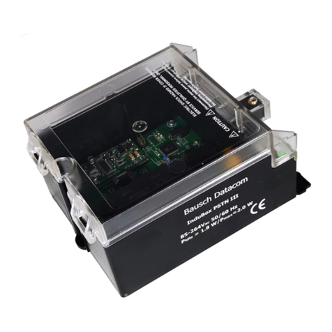
Bausch Datacom InduBox PSTN III Instruction sheet
Bausch Datacom
Bausch Datacom DinBox PSTN User manual
Bausch Datacom
Bausch Datacom Vega 56 PC2 User manual
Bausch Datacom
Bausch Datacom DinBox RTU M4 User manual
Bausch Datacom
Bausch Datacom InduBox GSM M4 Instruction sheet
Bausch Datacom
Bausch Datacom DinBox User manual
Popular Modem manuals by other brands

Comtrend Corporation
Comtrend Corporation NexusLink 3120 Connection guide

Paradyne
Paradyne COMSPHERE 3800PLUS installation instructions
Hitron
Hitron CODA-4589 Installation/Replacement Guide
Raisecom
Raisecom RC802-30B-FV35-S1 user manual
O2
O2 930D quick start guide
Novatel
Novatel Ovation U727 Getting started guide

