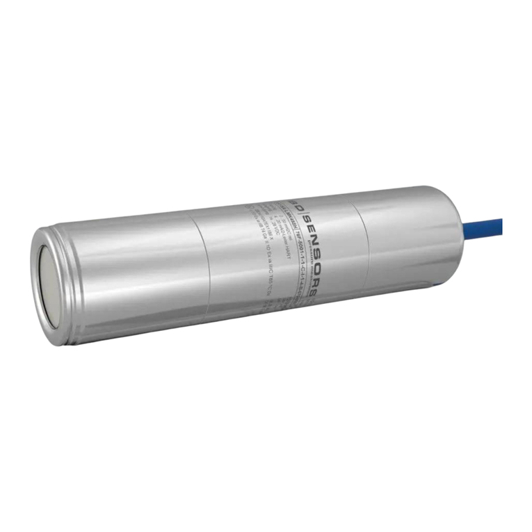
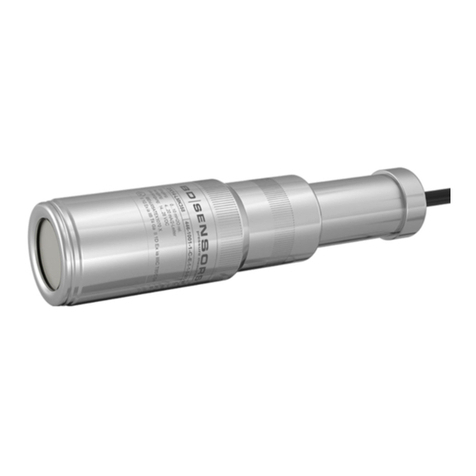
BD Sensors LMK 457 User manual

DE
EN
BD-Sensors-Str.1; 95199 Thierstein
Telefon: +49 (0) 92 35 / 98 11 0 | www.bdsensors.de
© 2022 BD|SENSORS GmbH -
Alle Rechte vorbehalten / All rights reserved
ID: MA_FS Schiff_D-E | Version: 07.2022.0
Montageanleitung /
Mounting instructions
Füllstandssonde für Marine und Offshore/
Probe for Marine and Offshore
LMK 457, LMK 458, LMK 458H, LMK 487
VOR GEBRAUCH SORGFÄLTIG LESEN
AUFBEWAHREN FÜR SPÄTERES NACHSCHLAGEN
READ THOROUGHLY BEFORE USING THE DEVICE
KEEP FOR FUTURE REFERENCE
Diese Montageanleitung stellt einen Auszug
aus der ausführlichen Betriebsanleitung dar.
Bitte fordern Sie diese an, falls Sie nicht mit
dem Produkt vertraut sind.
These mounting instructions are an excerpt from the complete
operating manual. If you are not familiar with the device, please
order it.
http://www.bdsensors.de
–Technische Änderungen vorbehalten –
–Technical modifications reserved –
WARNUNG - Um Gefährdungen des Bedienpersonals und
Schäden am Gerät auszuschließen, müssen die beschriebenen
Arbeiten von qualifiziertem Fachpersonal durchgeführt werden.
WARNUNG - Halten Sie sich an Sicherheitshinweise und
Handlungsanweisungen, die in der Betriebsanleitung aufgeführt
werden. Zusätzlich sind die geltenden Unfallverhütungsvor-
schriften, Sicherheitsbestimmungen sowie landesspezifische
Installationsstandards und die anerkannten Regeln der Technik
einzuhalten.
Haftungs- und Gewährleistungsbeschränkung
Nichtbeachtung der Montage- / Betriebsanleitung und techni-
schen Vorschriften, unsachgemäße und nicht bestimmungs-
gemäße Verwendung, Veränderung oder Beschädigung des
Gerätes führen zu Verlust der Gewährleistungs- und Haf-
tungsansprüche.
Bestimmungsgemäße Verwendung
Stellen Sie sicher, dass das Messmedium mit den medienbe-
rührten Teilen verträglich und das Gerät uneingeschränkt für
die Anwendung geeignet ist. Die im aktuellen Datenblatt auf-
geführten technischen Daten sind verbindlich.
Produktidentifikation
Anschlussbelegungstabelle
Elektrische Anschlüsse
Kabelfarben (IEC 60757)
Versorgung +
Versorgung −
Versorgung T+ (bei Pt 100)
Versorgung T–(bei Pt 100)
WH (weiß)
BN (braun)
YE (gelb)
GY (grau)
PK (rosa)
Schirm
GNYE (grün-gelb)
Anschlussschaltbilder
2-Leiter-System (Druck) / 3-Leiter-Anschluss (Temperatur)
2-Leiter System (Strom) HART
HINWEIS - Verwenden Sie für den elektrischen Anschluss
eine geschirmte und verdrillte Mehraderleitung.
Montage
Abziehen der Schutzkappe (falls erforderlich)
Zum Schutz der Membrane sind einige Geräte mit einer Kunst-
stoff-Schutzkappe ausgestattet. Ist ein Einsatz der Sonde in hö-
her viskosen Medien wie z. B. Schlämmen vorgesehen, ist diese
vor Inbetriebnahme abzuziehen. Dadurch wird die Sonde front-
bündig und das Medium gelangt an die Membrane.
HINWEIS - Achten Sie dabei unbedingt darauf, dass Sie die
Messzelle (7) unter der Schutzkappe nicht beschädigen!
Abziehen von Hand
1. Halten Sie die Sonde so, dass die Schutzkappe nach oben
zeigt.
2. Halten Sie mit einer Hand die Sonde am Sondenteil (1)
fest.
3. Ziehen Sie mit der anderen Hand die Schutzkappe (2) ab.
Abziehen mit Werkzeug (empfohlen)
Abb. 1 Abziehen der Schutzkappe
1. Halten Sie die Sonde so, dass die Schutzkappe nach oben
zeigt.
2. Schieben Sie ein dünnes Werkzeug (8), z. B. einen
Schraubendreher, gerade durch zwei gegenüberliegende
Bohrungen der Schutzkappe (2).
3. Hebeln Sie die Schutzkappe ab.
Zertifikat
Die Füllstandssonden LMK 457, LMK 458, LMK 458H und
LMK 487 erfüllen standardmäßig die Anforderungen des
DNV (Det Norske Veritas). Das Zertifikat können Sie auf
unserer Homepage herunterladen: http://www.bdsensors.de
Deutsch
GEFAHR
Lebensgefahr durch davonfliegende Teile, austretendes Medium, Stromschlag
- Montieren Sie das Gerät immer im druck- und stromlosen Zustand!
- Betreiben Sie das Gerät nur innerhalb der Spezifikation! (gemäß Datenblatt)
Lebensgefahr bei nicht bestimmungsgemäßer Installation
- Durchführung der Installation nur von fachspezifisch qualifiziertem Personal, das die Betriebsanleitung
gelesen und verstanden hat!
Tauchsonde Flanschsonde Einschraubsonde
Befestigen Sie die Tauchsonde ca. 25 Nm G3/4": ca. 15 Nm
sachgemäß, entsprechend G1": ca. 20 Nm
Ihren Anforderungen. G1 1/2": ca. 25 Nm
Verschiedenes Zubehör ist bei BD SENSORS erhältlich (Schellenbefestigung, Abspannklemmen, Montage- und Sondenflansche).
HINWEISE für Flansch- und Einschraubsonden:
-Verwenden Sie, soweit erforderlich, zur Abdichtung eine geeignete Dichtung, entsprechend Messstoff und zu messenden Druck.
Verwenden Sie bei Anschlüsse nach DIN 3852 kein zusätzliches Dichtmaterial wie Werg, Hanf oder Teflonband.
-Der erforderliche Anzugsmoment richtet sich nach den Gegebenheiten vor Ort (Werkstoff und Geometrie der Aufnahmestelle).
Die angegebenen Anzugsmomente gelten für die Füllstandssonde und dürfen nicht überschritten werden!
-Vermeiden Sie bei der Montage hohe mechanische Spannungen am Druckanschluss! Dies kann zu einer Verschiebung der
Kennlinie oder zur Beschädigung führen.
Typenbezeichnung Bestellcode Seriennummer
LMK 458H:
LMK 458
p
Versorgung +
Versorgung –
UB
I
Option Pt 100-
Temperaturfühler
p
I
Versorgung UB+
Versorgung UB−
Versorgung T+
Versorgung T−
Versorgung T−
UB

DE
EN
BD-Sensors-Str.1; 95199 Thierstein
Telefon: +49 (0) 92 35 / 98 11 0 | www.bdsensors.de
© 2022 BD|SENSORS GmbH -
Alle Rechte vorbehalten / All rights reserved
ID: MA_FS Schiff_D-E | Version: 07.2022.0
Montageanleitung /
Mounting instructions
Füllstandssonde für Marine und Offshore/
Probe for Marine and Offshore
LMK 457, LMK 458, LMK 458H, LMK 487
VOR GEBRAUCH SORGFÄLTIG LESEN
AUFBEWAHREN FÜR SPÄTERES NACHSCHLAGEN
READ THOROUGHLY BEFORE USING THE DEVICE
KEEP FOR FUTURE REFERENCE
Diese Montageanleitung stellt einen Auszug
aus der ausführlichen Betriebsanleitung dar.
Bitte fordern Sie diese an, falls Sie nicht mit
dem Produkt vertraut sind.
These mounting instructions are an excerpt from the complete
operating manual. If you are not familiar with the device, please
order it.
http://www.bdsensors.de
–Technische Änderungen vorbehalten –
–Technical modifications reserved –
WARNING - In order to avoid hazards to operators and
damages to the device, the following instructions have to be
performed by qualified technical personnel.
WARNING - Adhere to the safety and operating instructions
stated in the operation manual. Effective regulations on occupa-
tional safety, accident prevention as well as national installation
standards and approved engineering techniques must in addi-
tion be complied with.
Limitation of liability and warranty
Failure to observe mounting instructions / operating manual
or technical regulations, improper use and use not as in-
tended, and alteration of or damage to the device will result in
the forfeiture of warranty and liability claims.
Intended use
Ensure that the medium is compatible with the media-wetted
parts and that the device is suitable for the application without
restrictions. The technical data listed in the current data sheet is
binding.
Product identification
Pin configuration
Electrical connections
cable colours (IEC 60757)
Supply +
Supply -
Supply T+ (with Pt 100)
Supply T–(with Pt 100)
WH (white)
BN (brown)
YE (yellow)
GY (grey)
PK (pink)
Shield
GNYE (green-yellow)
Wiring diagrams
2-wire-system current (pressure) / 3-wire-system (temperature)
2-wire system (current) HART
NOTE - Use a shielded and twisted multicore cable for the
electrical connection.
Mounting
Removal of protective cap (if necessary)
For the protection of the diaphragm, some of the probes have a
plugged-on protection cap. If the device shall be used in high-
viscosity media such as sludge, a removal of the cap before
start-up is necessary. Thus, the sensor becomes flush, and the
medium will attain quickly to the diaphragm.
NOTE - Make sure that the sensor (7) under the protection cap
will not be damaged!
Removal by hand
1. Hold the probe in a way that the protection cap points up-
wards.
2. Hold the probe with one hand on the sensor section (1).
3. Remove the protection cap (2) with the other hand.
Removal with a tool (recommended)
Fig.2 Removal of protection cap
1. Hold the probe in a way that the protection cap points up-
wards.
2. Slide a small tool such as a screwdriver (8) straight through
two opposite drill holes in the protective cap (2).
3. Lever it off by moving up the handle of the screwdriver.
Certificates
The probes LMK 457, LMK 458, LMK 458H and LMK 487
fulfil the requirements of DNV (Det Norske Veritas) as
standard. The certificates are available for download on
our homepage: http:// www.bdsensors.de
English
DANGER
Danger of death from airborne parts, leaking fluid, electric shock
- Always mount the device in a depressurized and de-energized condition!
- Operate the device only within the specification! (according to data sheet)
Danger of death from improper installation
- Installation must be performed only by appropriately qualified persons who have read and understood the
operating manual.
Probe Flange version Screw-in version
Fasten the probe properly approx. 25 Nm G3/4": approx. 15 Nm
according to your requirements. G1": approx. 20 Nm
G1 1/2": approx. 25 Nm
Different mounting accessory is available from BD|SENSORS (mounting clamps, terminal clamps and mounting flanges).
NOTES for flange and screw-in versions:
- Use a suitable seal for the medium and the pressure to be measured, if necessary. For connections according to
DIN 3852 do not use any additional sealing material such as yarn, hemp or Teflon tape!
- The permissible tightening torque depends on the conditions on site (material and geometry of the mounting point).
The specified tightening torques are valid for the probe and must not be exceeded!
- When installing the device, avoid high mechanical stresses on the pressure port! This will result in a shift of the
characteristic curve or to damage, in particular in case of very small pressure ranges.
LMK 458H:
LMK 458
Type designation Ordering code Serial number
p
Supply +
Supply –
VS
I
Supply VS+
Supply VS−
Supply T+
Supply T−
Supply T−
VS
P
I
option Pt 100-
temperature
element
This manual suits for next models
3
Table of contents
Languages:
Other BD Sensors Measuring Instrument manuals

BD Sensors
BD Sensors BAROLI 02 User manual

BD Sensors
BD Sensors BAROLI 02 User manual

BD Sensors
BD Sensors DM 10 User manual

BD Sensors
BD Sensors BD SIMEX PAC-73S User manual

BD Sensors
BD Sensors KL 1 User manual

BD Sensors
BD Sensors DM01 User manual

BD Sensors
BD Sensors LMK 457 User manual

BD Sensors
BD Sensors PCB+ User manual

BD Sensors
BD Sensors DM 10 User manual

BD Sensors
BD Sensors DM10 User manual