BDH Elkay 376A-1 Manual

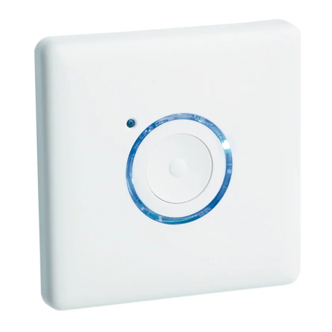
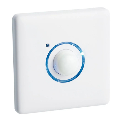
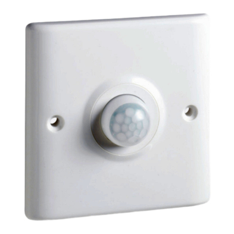
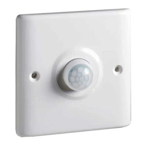
The Illuminated PIR Timer (2 wire)
is part of the Elkay family of switches,
timers and detectors which save
energy and increase convenience in
and around your home, garden
or premises.
Rating at 240V ac
• All load types 16A
• Time Delay: 2 min - 2 hrs
• Lux Level setting
• Blue Locator ring
• Last minute indicator
• Fits 25mm back boxes
• Override facility
• Single and multi way switching
Usage
The PIR timer has been designed to replace
a single gang light switch to control
lighting. The unit is switched on by the
detection of moving body heat within a
speci c range. When body heat is
no longer detected, the unit will switch o
after the adjustable time period has
elapsed. If moving body heat is detected
again during the timing period, the timing
sequence will restart. The unit has a lux
level adjustment, which prevents lighting
being switched on when there is su cient
light levels in the room.
When used with some low wattage lighting,
such as LEDs please ensure a capacitor of
2 microfarads (min.) is tted. Supplies of
suitable elkay capacitors can be found at
your stockist (Product no. PFCC-1).
Do not use this PIR with contactors.
IMPORTANT Please note that it is essential
that the live in and live out are identi ed prior
to commencing the installation and steps
1 – 5 are followed precisely. No neutral is
required on this product (See diagram 1).
Do not install the switch timer with the mains
power on as this can damage the product.
–
ILLUMINATED
PIR TIMER
376A-1
2 wire
Instruction Guide
BROOK DESIGN HARDWARE LTD
BDH
BDH
BROOK DESIGN
HARDWARE LTD
BDHBROOK DESIGN
HARDWARE LTD
BDH
BROOK DESIGN
HARDWARE LTD
BDH

• Not suitable for use with contactors
• Do not megger test or insulation
resistance test this product.
• Remove before testing or test circuit
prior to fi tting
Your Elkay unit is compatible with a single
gang, 25mm deep British Standard
accessory plate. Please ensure that the
top and bottom lugs are removed from
metal wall boxes prior to tting.
For 16mm boxes Elkay provide a spacer
plate (product code 220A-1) to take box
depth to 25mm. For two way lighting
(see diagram 2), you will require an activator.
Please note it is not possible to use two 2
wire masters in the same circuit.
Diagram 1
Wiring diagram for a
single unit master.
Diagram 4 – Time settings
Please note: The black bar denotes the position of the dip switch.
Diagram 2
Wiring diagram for a Master and Activator.
Diagram 3
Positioning
Use the detection range to determine a
suitable location for the sensor. Avoid
subjecting to direct sunlight, not adjacent
to the load, vibrating surfaces or near
forced air heating and ventilation.
This product requires a 24 hour power
supply. The battery inside the unit recharges
when the light source or appliance is
switched OFF. Where the supply may be
interrupted or isolated regularly we must
recommend our products from the three
wire range.
LIVE IN
NEUTRAL
LIVE OUT
5 - 7m
4 - 6m
5 - 7m
3 - 4m
5 - 7m
4 - 6m
5 - 7m
3 - 4m
LIVE IN
LIVE OUT
NEUTRAL
7 metres approx.
2.4 metres
7 metres approx.
CEILING
FLOOR
LIVE IN
NEUTRAL
LIVE OUT
LIVE IN
LIVE OUT
Battery
LIVE IN
LIVE OUT
DIL
switches
Battery
NEUTRAL
Battery
LIVE IN
NEUTRAL
LIVE OUT
Battery
Battery
*Optional wire for blue indicator
ring on pushbutton activators only.
Battery
LIVE IN
LIVE OUT
Battery
Battery
*Optional wire for blue indicator
ring on pushbutton activators only.
DIL
switches
Battery
DIL
switches
DIL
switches
Battery
DIL
switches
Battery
DIL
switches
Battery
DIL
switches
NEUTRAL
2INSTRUCTION GUIDE
|
ILLUMINATED PIR TIMER – 2 WIRE
2 mins 5 mins 10 mins 20 mins 40 mins 60 mins 90 mins 120 mins
ON DIP
4
3
2
1
ON DIP
4
3
2
1
ON DIP
4
3
2
1
ON DIP
4
3
2
1
ON DIP
4
3
2
1
ON DIP
4
3
2
1
ON DIP
4
3
2
1
ON DIP
4
3
2
1
Side view
Plan view
100
o
approx.
60
o
approx.
5 - 7m
4 - 6m
5 - 7m
3 - 4m
LIVE IN
NEUTRAL
LIVE OUT
5 - 7m
4 - 6m
5 - 7m
3 - 4m
5 - 7m
4 - 6m
5 - 7m
3 - 4m
LIVE IN
LIVE OUT
NEUTRAL
7 metres approx.
2.4 metres
7 metres approx.
CEILING
FLOOR
LIVE IN
NEUTRAL
LIVE OUT
LIVE IN
LIVE OUT
Battery
LIVE IN
LIVE OUT
DIL
switches
Battery
NEUTRAL
Battery
LIVE IN
NEUTRAL
LIVE OUT
Battery
Battery
*Optional wire for blue indicator
ring on pushbutton activators only.
Battery
LIVE IN
LIVE OUT
Battery
Battery
*Optional wire for blue indicator
ring on pushbutton activators only.
DIL
switches
Battery
DIL
switches
DIL
switches
Battery
DIL
switches
Battery
DIL
switches
Battery
DIL
switches
NEUTRAL
Battery
LIVE IN
NEUTRAL
LIVE OUT
Battery
Battery
*Optional wire for blue indicator
ring on pushbutton activators only.
Battery
LIVE IN
LIVE OUT
Battery
Battery
*Optional wire for blue indicator
ring on pushbutton activators only.
DIL
switches
Battery
DIL
switches
DIL
switches
Battery
DIL
switches
Battery
DIL
switches
Battery
DIL
switches
NEUTRAL
Master Activator

Installation Steps
DO NOT APPLY MAINS UNTIL INSTRUCTED!
Step 1
Ensure the mains power to the circuit is
switched o. Place the previously identied
live in wire as per diagram, into the
terminal marked L In, the switched live
out into the terminal marked L out
(see diagram 1).
Step 2
Set the timing as per timing table
(see diagram 4). The black square illustrates
where the dip switch should be situated.
For example:
10min 1 = OFF, 2 = ON, 3 = OFF, 4 = ON
Note: Dip switch must be positioned away
from the numbers for ON and against the
numbers for OFF.
Step 3
When initialising rotate lux level to
maximum (+).
Step 4
Switch on battery using dip switch 4.
You will notice a red ashing LED light on
the front of the unit. Attach the unit to the
wall with the screws provided then clip the
front fascia plate on. Switch on mains
power supply, the unit will default your
load to the ON condition (Blue ring OFF) for
approximately 60 seconds before switching
OFF (Blue ring comes ON and red LED will
ash periodically during initialisation).
Please leave for appropriately 5 minutes to
allow the unit to initialise. There is no
longer ANY need to press the PIR dome.
Step 5
Reduce lux level to sucient level by rotating
clockwise towards (–) if required. All the way
to the minus (-) represents zero lux level.
Operation of the Unit
• In standard operation, the PIR will now
sense body heat when passing through
the detection zone. Each time the PIR
is triggered the red LED will light and reset
back to the start of the timing period.
The unit will then wait 20 seconds
approximately before allowing the PIR
unit to sense and re-trigger the timing
period again.
• If no one is present in the room or the
detection zone is not passed through during
its set time period, the timer will time out,
turning the lights or appliance o and
the blue locator ring will light up.
• The PIR unit will only trigger the lights
or appliance if the ambient light level
is below that set on the lux level
adjustment potentiometer. See diagram
1 for location of potentiometer
(lux level adjustment).
• When the ambient light level is sucient
the override switch (pressing the lens as
shown in picture 5) can be used to turn
on the lights for the set period of time.
This can be used when additional light is
required in the room.
3
INSTRUCTION GUIDE
|
ILLUMINATED PIR TIMER – 2 WIRE
Side view
Plan view

Installation Notes
In case of a power failure, your Elkay PIR
timer will attempt to automatically
re-start, which will cause the blue locator
ring to ash. The unit will attempt to
locate the power source. The unit will
attempt to locate the power source
between 4-6 times before powering
down to sleep mode.
Once power is re-installed to reactivate
the unit switch battery OFF for 15 seconds
then back ON and leave unit to
re-initialize itself.
Override
Your Elkay timer has the added bene t of a
manual override facility. This allows the
lights to be turned on for the set period of
time when the ambient level is such that
the lights would not usually come on.
In dark conditions the manual override
disables the PIR allowing the lights to be
turned o inde nitely or when the
override switch is re-pressed.
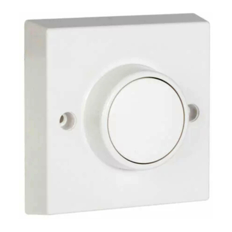
Activator and Momentary Fitting
When connecting with Activators use three
core cable connecting the Live In, Live Out
and Trigger terminals as shown in diagram 2.
The optional wire to the Activators only
applies to the 350A-1 Pushbutton Activator
units and is ideal for retro tting
(See diagram 2).
Please note that the Trigger terminal is the
third terminal. Momentary or activating
switches can also be used and can be
connected back to the Live In and the
Trigger terminal on the master.
Brook House,
Dunmurry Industrial Estate,
Dunmurry,
Belfast BT17 9HU
T +44 (0)28 9061 6505
F +44 (0)28 9061 6518
E info@elkay.co.uk elkay.co.uk
BROOK DESIGN HARDWARE LTD
BDH
B
DH
BROOK DESIGN
HARDWARE LTD
BDHBROOK DESIGN
HARDWARE LTD
BDH
BROOK DESIGN
HARDWARE LTD
BDH
Picture 5
Technical Helpline
For further help or assistance or information on this or other products in the range
please call the Elkay Technical team on +44 (0)28 9061 6505. Please call the Technical
helpline before returning any products to your stockist. In the unlikely event that you
have to return your product, please ensure you switch the battery off fi rst. These
instructions are available in other languages. Please refer to our website www.elkay.co.uk
Instrukcje są również dostępne w innych językach. Prosimy o zapoznanie się z
naszą stroną internetową www.elkay.co.uk lub www.elkaypolska.pl
Important Notice
All wiring should be carried out by a
competent person or a qualified electrician
and should be fitted to current IEE wiring
regulations BS 7671.The circuit should
be isolated before carrying out any work.
Failure to adhere to the instructions will
invalidate the warranty.
Elkay (Europe), 51C Milicka, Trzebnica, 55-100, Poland
Other BDH Timer manuals
