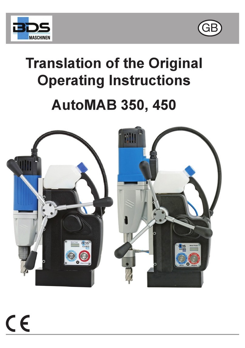
BDS MAB 1300 Quick guide

MAB 1300
Translation of the Original
Operating Instructions
GB

11
5
3
6
1
4
8
12
10
15
14
2
7
9
Fig. 2
31
32
Fig. 1
21
23
22
24
13

3MAB 1300
GB
Table of Contents
General instructions ................3
Safety ............................5
Components / delivery contents .....10
Before using for the rst time .......11
Preparation. . . . . . . . . . . . . . . . . . . . . . .11
Using............................16
Eliminating blockages. . . . . . . . . . . . . .20
Cleaning/maintenance .............20
Storage ..........................21
Troubleshooting ..................22
Technical data ....................23
EC Declaration of Conformity .......24
Dear Customer,
Before using the machine, please read the
operating instructions contained in these
operating instructions on startup, safety,
intended use as well as cleaning and care.
The links and illustrations in these instruc-
tions refer to the illustrations on the inside
of the cover.
Keep these operating instructions for later
use and pass them onto the next owner of
the machine.
General instructions
Copyright
This document is subject to copyright. Du-
plication or reprinting, even in part as well
as reproduction of the illustrations, even
if modied, is only permitted with written
consent of the manufacturer.
Liability disclaimer
All technical information, data and in-
structions contained in these operating
instructions for startup, operation and care
correspond to the latest requirements at the
time of printing.
The manufacturer assumes no liability for
damage or injury resulting from failure to
observe the operating instructions, use for
other than the intended purpose, unprofes-
sional repairs, unauthorised modications
or use of non-approved spare parts and
accessories, tools and lubricants.
Instructions on disposal
The packaging materials used can be
recycled. When no longer required,
dispose of the packing materials according
to local environmental regulations.
This product may not be disposed of
in the European Union via the normal
household refuse. Dispose of the
device via communal collection points.
The lubricant used can contain
substances dangerous to the
environment. Dispose of the lubricant
according to local regulations. Observe the
disposal instructions from the lubricant
manufacturer.
General instructions

4MAB 1300
GB
Safety warning structure
The following warnings are used in these
operating instructions:
DANGER
A warning of this category indicates
an impending dangerous situation.
If the dangerous situation is not avoid-
ed, it may lead to serious injury or even
death.
►Follow the instructions in this warning
to avoid possible danger of serious
injury or even death.
WARNING
A warning of this category indicates a
potentially dangerous situation.
If the dangerous situation is not avoid-
ed, it may lead to serious injury or even
death.
►Follow the instructions in this warning
to avoid the danger of serious injury
to persons.
ATTENTION
A warning of this category indicates
potential danger to property.
If the situation is not avoided, it may lead
to material damage.
►Follow the instructions in this warning
to avoid material damage.
NOTE
►A note indicates additional information
that simplies the use of the machine.
Intended use
The machine is intended solely for drilling
operations in magnetic and non-magnetic
metals, and for cutting threads, counter-
sinking and reaming within the limits speci-
ed in the technical data.
Any use other than previously stated is
considered as improper use.
WARNING
Danger due to improper use!
If not used for its intended purpose and/
or used in any other way, the machine
may be or become a source of danger.
►Use the machine only for its intended
purpose.
►Observe the procedures described in
these operating instructions.
No claims of any kind will be accepted for
damage resulting from use of the system
for other than its intended purpose.
The risk must be borne solely by the user.
NOTE
►If used commercially, pay attention to
compliance with the accident preven-
tion and occupational safety regula-
tions.
General instructions

5MAB 1300
GB
Safety
NOTE
When using electrical tools, the following
fundamental precautions must be taken
to protect against electric shock and the
risk of injury and re!
Fundamental safety instructions
■Do not use the machine in potentially
ammable or explosive environments.
■Persons, who are unable to safely op-
erate the machine due to their physical,
mental or motor abilities, my only use
the machine under the supervision or
instruction of a person responsible.
■Persons with heart pacemakers or other
medical implants must not use this
machine.
■Children are not permitted to use the
machine.
■Inspect the machine for visible signs of
damage before use. Do not operate a
damaged machine.
■Before beginning work, check the condi-
tion of the safety chain and the function
of the switches on the machine.
■Repairs to the connecting cable may
only be performed by a qualied elec-
trician.
■Repairs to the machine may only be
performed by an authorised specialist
workshop or factory customer service.
Unqualied repairs can lead to consid-
erable danger for the user.
■Repairs to the machine during the guar-
antee period may only be performed by
a customer service authorised by the
manufacturer, otherwise the guarantee
is invalid.
■Defective parts may only be replaced
with original spare parts. Only these
parts ensure that the safety require-
ments are met.
■Do not leave the machine unsupervised
during operation.
■Store the machine in a dry, temperate
location out of the reach of children.
■Do not allow the machine to stand out-
side and do not expose to moisture.
■Make sure that your work area is su-
ciently lit (>300 Lux).
■Do not use low-power machines for
heavy working.
■Pay attention to cleanliness at the
workplace.
■Keep the machine clean, dry and free of
oil and grease.
■Follow the instructions on lubricating
and cooling the tool.
Safety

6MAB 1300
GB
Danger from electric current!
DANGER
Danger to life from electrical current!
Contact with live wires or components
can lead to serious injury or even
death!
Observe the following safety precautions
to avoid any danger from electric current:
►Do not open the housing of the
machine. Risk of electric shock from
touching live connections.
►Never immerse the machine or mains
plug in water or other liquids.
►Only use extension cables or cable
drums with a cable cross-section of at
least 1.5 mm².
►Only use extension cables that are
approved for the location of use.
►Check the condition of the extension
cable regularly and replace if dam-
aged.
►Avoid bodily contact with grounded
parts (e.g., pipes, radiators, steel
girders) to reduce the risk of electric
shock in the event of a defect.
►When using the machine outside or in
a humid environment, an RCD (resid-
ual circuit device) must be used.
Risk of injury!
WARNING
Risk of injury from engine starting
unintentionally!
Pay attention to the following safety
notes to avoid danger from motor starting
unintentionally:
For safe stopping of the motor:
►Press the red button (O) of the motor
switch (21).
►Switch o the machine with the ON/
OFF switch (main switch) (23).
►Disconnect the voltage supply (pull
out the mains plug).
WARNING
Improper handling of the machine
increases the risk of injury!
Pay attention to the following safety
instructions in order not to injure others
or yourself:
►Operate the machine only with the
protective equipment specied in
these instructions (see section “Per-
sonal protective equipment”).
►Do not wear protective gloves when
the machine is running. A glove can
be caught by the drilling machine and
torn o the hand. Risk of losing one
or more ngers.
►Remove loose jewellery before begin-
ning work.
►Wear a hair net if you have long hair.
Safety

7MAB 1300
GB
WARNING
►Always switch o the machine before
changing tools, performing main-
tenance or cleaning. Wait until the
machine has come to a complete
standstill.
►Always remove the plug from the
mains socket before changing tools,
cleaning or performing maintenance
work in order to avoid unintentional
starting of the machine.
►Do not put your hand into the ma-
chine while it is in operation. Remove
swarf only when the machine is at
a standstill. Wear protective gloves
when removing swarf.
►When working on scaolding, the op-
erator must be secured with a safety
belt as the machine can oscillate dan-
gerously in the event of interruption to
the power supply.
►Check for secure clamping of the
electromagnets on the substrate be-
fore every use (see section “Prepa-
ration”).
►Secure the machine with the safety
chain (D) supplied when working in
an inclined or vertical position and
during overhead work. The machine
could fall down if the magnet is loos-
ened or the power fails.
►Check that the tool is tightened
securely before using (see section
“Inserting the tool”).
►Do not allow the connecting cable to
hang over edges (trip eect).
Transporting the machine
WARNING
Danger resulting from the heavy
weight of the machine!
Due to the heavy weight of the machine,
observe the following instructions
►Only transport the machine with a
suitable means of transport.
►Lifting the machine manually should
be carried out by two persons.
►When transporting the machine with a
crane, use suitable lifting equipment.
Pay attention to the carrying capacity
of the lifting equipment.
Preventing damage
ATTENTION
Potential damage to property if the
machine is improperly used!
Observe the following instructions to
avoid damage to property:
►Before connecting the machine, com-
pare the connection data (voltage and
frequency) on the rating plate with
those of your mains power supply.
The data must correspond in order to
avoid damage to the machine.
►Always use the handle to carry the
machine and not the connecting
cable.
►Do not pull the mains cable to remove
the plug from the mains socket.
Safety

8MAB 1300
GB
ATTENTION
►Do not crush the connecting cable.
►Do not subject the connecting cable
to heat or chemical liquids.
►Do not pull the connecting cable
across sharp edges or hot surfaces.
►Lay the connecting cable in such
a way that it cannot be caught and
wound up in the rotating part of the
machine.
Safety equipment
Restart protection
NOTE
►The machine stops automatically
when the magnetic clamp is switched
o or if the power supply is interrupt-
ed.
In order to prevent the machine from
starting unexpectedly after switching on the
magnetic clamp again or after reconnection
following interruption to the power supply
("restart protection"), the machine must be
switched on using the ON/OFF switch.
Magnet indicator
The magnet indicator (22) provides visual
indication of the magnetic clamping force.
■Magnet indicator (22) lights up GREEN:
The magnetic clamping force satises
the minimum requirements.
Processing can take place.
■Magnet indicator (22) lights up RED:
Insucient magnetic clamping force.
Do not process with the machine. This
can be the case if the material is too
thin, the surface is uneven or if coated
with paint, scale or zinc.
Overheat protection
The machine is also protected against
overheating. If the machine becomes too
hot, it switches o automatically.
Perform the following steps before continu-
ing to work with the machine:
■Remove any blockages that may have
occurred.
(see section “Eliminating blockages”)
■Allow the machine to run at idle for
approx. 2 minutes.
The machine is then ready for operation
again.
Safety

9MAB 1300
GB
Slip clutch
If the drill blocks, the gearbox is protected
by a slip clutch.
Symbols on the machine
The symbols on the machine have the
following meaning:
Symbol Meaning
Electric shock hazard!
Heavy load!
Read the operating instructions
before beginning work!
Wear protective goggles and
ear protection!
Personal protective equipment
Wear the following protective equipment at
all times when operating the machine:
Symbol Meaning
Close-tting work protection
clothing with a low tear strength
Goggles for protecting eyes
against ying parts and liquids
and ear protection in areas with
noise emission >80 dB(A)
Safety shoes for protecting feet
against falling objects.
Also wear the following protective equip-
ment during special work:
Symbol Meaning
Helmet for protecting your head
against falling objects
Wear a harness where there is
a danger of falling.
Gloves for protection against
injuries
Safety

10 MAB 1300
GB
Components / delivery con-
tents
Machine overview
1 Core drill
(not supplied as standard)
2 Tool mounting
3 Support strut
4 Internal lubrication
5 MK4 spindle taper
6 Opening for ejector pin
7 4-speed gearbox with selector
8 Speed and torque controller
(see g. 2)
9 Engine drive
10 Transport lug
11 Hand lever
12 Handle
13 Operating panel (see g. 1)
14 Machine slide and guide
15 Magnetic foot
Operating panel
(see g. 1)
21 Motor ON/OFF switch
22 Magnet indicator (Magnet Power)
23 Magnet ON/OFF switch
(main switch)
24 Direction of rotation switch
(see g. 2)
31 Speed setting
32 Torque setting
Scope of supply
Machine MAB 1300
A ZAP 200 reducing ring
(32 mm Weldon to 19 mm Weldon)
B ZAK 075 ejector pin
C ZAK 090 ejector pin
D ZAK 100 ejector pin
E ZAK 120 ejector pin
F Safety belt
G MK4 ejector pin
HHexagonal oset screwdriver, size SW6
Metal transport case (not illustrated)
Operating instructions/guarantee card
(not illustrated)
Components / delivery contents

11MAB 1300
GB
Before using for the rst time
Transport inspection
As standard, the machine is supplied with
the components indicated in the “Scope of
supply” section.
NOTE
►Check for visible signs of damage or
missing items on delivery. Report an
incomplete or damaged delivery to
your dealer/supplier immediately.
Preparation
This section contains important instructions
on the required preparation before begin-
ning any work.
Additional safety measures for
certain work
Additional safety precautions must be
taken for the following operations with the
machine:
Non-horizontal work position
WARNING
Risk of injury from a falling machine.
When working in an inclined or vertical
position or during overhead work, the
machine must be secured using the
safety belt (F) supplied to prevent it from
falling.
►Check the safety belt for correct func-
tion before using. A damaged safety
belt must not be used. Replace a
damaged safety belt immediately.
WARNING
►Attach the safety belt in such a way
that the machine can fall away from
the operator if it slips.
►Lay the safety belt as taught as possi-
ble around the handle of the machine.
►Check the secure tting of the safety
chain and lock before starting work.
►Use the protective equipment stipulat-
ed in the section “Personal protec-
tive equipment”.
Work on scaolding
WARNING
Risk of falling from sudden oscillating
movements of the machine.
When working on scaolding, the
machine can make a sudden oscillating
movement on starting or in the event of
interruption to the power supply.
►Secure the machine with the safety
belt (F) supplied.
►Wear a safety harness to protect
yourself against falling.
Before using for the rst time

12 MAB 1300
GB
Check the condition
of the substrate
The magnetic clamping force is depend-
ent on the condition of the substrate. The
clamping force is signicantly reduced by
paint, zinc and scale coatings and rust.
The substrate must satisfy the following
conditions in order to achieve sucient
magnetic clamping force:
■The substrate must be magnetic.
■The clamping surface and the magnetic
foot (15) must be clean and grease-
free.
■The clamping surface must be com-
pletely smooth and level.
NOTE
►Clean the substrate and the magnetic
foot (15) of the machine before use.
►Remove any unevenness and loose
rust from the substrate.
►The BDS range of accessories in-
cludes special holding devices.
The best clamping eect is obtained on
low-carbon steel substrate with a thickness
of at least 20 mm.
Steel with low thickness
When drilling into low thickness steel, an
additional steel plate (minimum dimensions
100 x 200 x 20 mm) must be placed under
the workpiece. Secure the steel plate to
prevent it from falling.
NF metals or workpieces with an uneven
surface
A special holding device must be used
when drilling into NF metals or into work-
pieces with an uneven surface.
NOTE
►BDS oers a range of accessories
with special clamping devices for
tubes and non-magnetic materials.
Preparing

13MAB 1300
GB
Dismantling/assembling the tool
holder
WARNING
Risk of injury!
►Only dismantle/mount the tool holder
when the machine is switched o and
at a standstill. Pull the plug out of the
mains socket.
►After mounting, check for secure
seating of the tool holder.
►Only use the tool holders appropriate
to this machine.
Dismantling the tool holder
Unscrew and remove the screws of
the retainer (3) on the magnetic foot.
Push the tool holder (2) out of the
morse taper with the ejector pin (G).
Remove the tool holder with the retain-
er.
NOTE
►Keep the tool holder in the transport
case for later use.
Assemble the tool holder
Insert the tool holder (2) from below
into the morse taper (5) of the ma-
chine.
Put the retainer into the guide on the
magnetic foot and secure it with the
screws.
Inserting the tool
WARNING
Risk of injury!
►Do not use damaged, contaminated
or worn tools.
►Change tools only when the machine
is switched o and at a standstill. Pull
the plug out of the mains socket.
►After inserting, check that the tool is
engaged securely.
►Only use tools, adapter and accesso-
ries that match the machine.
The machine is equipped with an MK tool
holder.
Depending on the type of tool to be used,
corresponding tool holders, drill chucks or
adapters must be employed.
Tool
with:
Tool holder
to be used
MK3 cone Use adapter sleeve (availa-
ble as accessory).
Dismantle the tool holder
with the retainer.
MK4 cone Insert the tool directly into the
spindle taper (5). Disman-
tle the tool holder with the
retainer.
19 mm
Weldon shaft
Use ZAP 200 reducing ring.
32 mm
Weldon shaft
Use MK4/Weldon 32mm tool
holder with retainer (delivery
condition).
Preparing

14 MAB 1300
GB
Straight
shank
Use drill chuck with tapered
mandrel (available as acces-
sory). If necessary, use an
adapter sleeve.
Thread
tap
Use industrial tool holder with
Weldon Shank and matching
ZGA adapter for drill taps
(available as accessory).
NOTE
►To insert the tools, the tool holder
must be mounted or dismantled (see
section “Dismantling/assembling
the tool holder”).
Weldon industrial tool holder (Fig. 3)
Inserting the tool
Before inserting, clean the Weldon
shank of the tool and the tool holder.
Loosen both hexagonal socket screws
in the tool holder using the Allen
wrench (H) supplied.
Insert the tool into the tool holder.
NOTE
►Use the ZAP 200 (A) reducing ring for
tools with 19mm Weldon shank.
►Insert the appropriate ejector pin
(B, C, D, E) before inserting a core
drill.
Tighten both hexagonal socket screws
in the tool holder using the Allen
wrench (H) supplied.
Removing the tool
Loosen both hexagonal socket screws
in the tool mount using the Allen
wrench (H) supplied and remove the
tool from below.
Remove the ZAP 200 reducing ring (A),
if necessary.
MK tool/industrial tool holder
WARNING
Risk of injury from incorrectly inserted
tool!
An insuciently secured tool can lead to
serious injuries.
►Check the proper seating of the tool,
adapter or drill chuck in the MK tool
mounting.
NOTE
►When using tools with MK4 taper,
the toolholder with retainer must be
dismantled.
For further information, see the sec-
tion “Dismantling/assembling the
tool holder”.
Fitting the tool/industrial tool holder
Before tting, clean the tool shank,
adapter or industrial tool holder and
the spindle taper (5) of the machine.
Insert the tool into the spindle taper (5)
of the machine from below.
NOTE
►When using tools/adapters with MK3
taper, use MK4:3 adapter sleeve.
Preparing

15MAB 1300
GB
Removing the tool
Turn the tool until the ejector pin (G)
slips into the opening for the ejector
pin (6).
Lever out the tool with the ejector
pin (G) or loosen the tool by tapping
against the ejector pin.
Using the drill chuck
WARNING
Risk of injury!
An insuciently secured tool can lead to
serious injuries.
►Turn the drill chuck only with the
chuck key provided.
►Always remove the chuck key from
the drill chuck after tightening or
loosening.
NOTE
►When using tools with MK4 taper,
the toolholder with retainer must be
dismantled.
For further information, see the sec-
tion “Dismantling/assembling the
tool holder”.
Inserting the drill chuck
Insert the drill chuck onto the tapered
mandrel and insert the combination
into the spindle taper (5) of the ma-
chine. If necessary, use an adapter
sleeve.
Open the drill chuck and insert the tool
into the drill chuck.
Close the drill chuck by hand and then
turn the drill chuck with the chuck key.
Removing the drill chuck
Loosen the drill chuck with the chuck
key and remove the tool.
Turn the drill chuck until the ejector
pin (G) slips into the opening for the
ejector pin (6).
Lever out the drill chuck with the ejec-
tor pin (G) or loosen the drill chuck by
tapping against the ejector pin.
Adapter for drill taps (Fig. 4)
Inserting the tool
Insert the tool holder with Weldon
shank into the spindle taper (5) of the
machine.
Insert the drill tap into its matching
adapter.
Insert the drill tap with adapter into the
industrial tool holder.
Tighten both hexagonal socket screws
in the tool holder.
NOTE
►For cutting threads, the toolholder
with retainer must be dismantled.
For further information, see the sec-
tion “Dismantling/assembling the
tool holder”.
►BDS oers matching industrial tool
holders and drill tap adapters in its
range of accessories.
Removing the tool
Loosen both hexagonal socket screws
in the tool holder and remove the
adapter with thread tap from below.
Remove the drill tap by pulling it down-
wards out of its adapter.
Preparing

16 MAB 1300
GB
Using
Activating/deactivating the mag-
netic clamp
Activating the magnetic clamp
ATTENTION
►To prevent the magnet from overheat-
ing, switch on the magnetic clamp
only when the machine is standing on
a magnetic substrate.
Switch the magnet (23) ON/OFF
switch on. The indicator lamp in the
magnet (23) ON/OFF switch on.
Check the magnet holding force with
the magnet indicator (“MAGNET
POWER” (22) indicator light).
MAGNET POWER
indicator light
Magnetic holding
force condition
GREEN Sucient
magnetic holding
force
RED Insucient magnet-
ic holding force
ATTENTION
►The maximum magnetic clamping
force is only available after switching
on the motor.
Deactivating the magnetic clamp
Hold the handle tightly (12) to stop the
machine from slipping.
Switch the magnet (23) ON/OFF
switch o. The indicator lamp in the
magnet (23) ON/OFF switch extin-
guishes.
Switching the machine ON/OFF
Using the ON/OFF switch (21), turn
the machine ON with the green
button (I) and OFF with the red but-
ton (O).
NOTE
►The machine can only be switched on
when the magnetic clamp has been
switched on.
►Allow a severely overheated machine
to run on at idle speed for approx.
2 minutes.
►The machine switches o automati-
cally in the event of a power failure or
if the magnetic clamp is switched o.
Selecting the speed range
ATTENTION
►Switch the gear stages only with the
machine at standstill.
NOTE
►Select the speed range according to
the material and drilling diameter.
The machine is equipped with a gearbox
that has four mechanical gear stages.
The gear stage is set using both selector
levers (7) on the side of the gear box.
Using

17MAB 1300
GB Using
To select the desired gear stage,
switch the machine o and set both
selector levers (7) to the desired
speed as shown in the table below.
Gear
level
max.
speed
Selector lever
left right
Level 1 80 rpm ● ●
Level 2 120 rpm ●● ●
Level 3 350 rpm ● ●●
Level 4 550 rpm ●● ●●
Setting the speed
In addition to the mechanical gearbox, the
machine is also equipped with full-wave
control electronics for stepless variable
speed adjustment.
First set the appropriate gear stage,
then adapt the speed using the elec-
tronic speed control (31).
Gear stage Speed range
Level 1 30 - 80 min-1
Level 2 50 - 120 min-1
Level 3 130 - 350 min-1
Level 4 210 - 550 min-1
NOTE
►If possible, always select a setting
with low gear stage and high motor
speed. The motor is then set with a
higher torque and therefore protect-
ed against overheating under heavy
load.
Setting the
torque cut-o
ATTENTION
►Do not use this function to switch o
the machine when cutting threads in
blind holes.
In order to protect the tool, the maximum
torque of the machine can be set using the
controller (32).
The machine switches o when it reaches
the maximum set torque. After switching o,
the machine must be switched o and on
again using the ON/OFF switch (21).

18 MAB 1300
GB
Using
Drilling with the machine
Drilling with twist drills
When drilling with twist drills, proceed as
follows:
Remove the tool holder with the retain-
er.
Push twist drills with MK taper into the
spindle taper (5) of the machine from
below.
Push twist drills with straight shank
into the drill chuck after tting the drill
chuck (see section “Using the drill
chuck”).
Position and x the machine at the
location of use.
Switch on the clamping magnet and
check the magnetic holding force (see
section “Activating/deactivating the
magnetic clamp”).
Select a suitable speed and switch on
the machine.
Direct the drill to the material with the
handle (11).
NOTE
Observe the following instructions when
drilling with twist drills:
►Under excessive pressure, the drill
can wear out and the machine can be
overloaded.
►Make sure that swarf is removed
regularly. With larger drilling depths,
break up the swarf.
Drilling with core drills
When drilling with core drills, proceed as
follows:
Assemble the tool holder and the
retainer.
Use the ZAP 200 (A) reducing ring for
core drills with 19mm Weldon shank.
Connect the cooling lubricant system.
Insert the appropriate ejector pin into
the core drill and insert the core drill
into the tool holder.
Position and x the machine at the
location of use.
Switch on the clamping magnet and
check the magnetic holding force (see
section “Activating/deactivating the
magnetic clamp”).
Select a suitable speed and switch on
the machine.
Direct the drill to the material with the
handle (11).

19MAB 1300
GB
NOTE
Observe the following instructions when
drilling with core drills:
►Drilling with core drills does not require
great force. The drilling process is not
accelerated by higher pressure. The
drill wears faster and the machine can
be overloaded.
►Use the high-performance BDS 5000
cutting oil in the cooling lubricant sys-
tem of the machine.
►The cooling lubricant system cannot
be used when working overhead. In
this case, use the high-performance
ZHS 400 grease spray. Spray the drill
on the inside and outside before drill-
ing. In the case of larger drill depths,
repeat this procedure.
►Make sure that swarf is removed regu-
larly. With larger drilling depths, break
up the swarf.
Thread cutting
The machine is equipped with reversible
direction of rotation and can also be used
for cutting threads.
In order to cut threads, proceed as follows:
Drill the hole for the thread.
Switch o the machine and set the
lowest gear stage and speed.
Using
Set the direction of rotation to clock-
wise (right = R) at switch (24).
Tighten the drill tap in the machine
using the appropriate drill tap adapter.
Switch on the machine and place the
drill tap onto the drilled hole.
Use the hand lever (11) without ex-
erting pressure to guide the machine
until the desired thread length has
been cut.
Switch o the machine and set the
direction of rotation to anti-clockwise
(left = L) at switch (24).
Switch on the machine again and al-
low the drill tap to completely emerge
out of the workpiece. Then use the
hand lever (11) to guide the machine
slide upwards in order to avoid dam-
aging the top of the thread.
Reaming/counter-sinking
Thanks to its wide range of operating
speeds, the machine can also be used for
reaming or counter-sinking.
ATTENTION
►When reaming and counter-sinking,
observe the limits stated in the techni-
cal data for the tools to be used.
►Do countersinking manually because
the automatic feed unit does not have
a drilling depth setting.

20 MAB 1300
GB
Eliminating blockages
WARNING
Danger of cut injuries from broken
tool parts or swarf.
►Put protective gloves on before start-
ing work.
Blockages caused by a broken tool:
Switch o the machine. Remove plug
from the mains socket.
Move the machine slide to the upper
position with the help of the hand
lever (11).
Replace defective tool. Remove swarf.
Other blockages:
Switch the machine o using the motor
switch. Leave the magnetic clamp
switched on.
Move the machine slide to the upper
position with the help of the hand
lever (11).
Remove swarf and check tool.
NOTE
►The BDS range of accessories in-
cludes special devices
(e.g., POW 200) for removing swarf.
Eliminating blockages
Cleaning/maintenance
WARNING
►Switch o the machine and discon-
nect the voltage supply before per-
forming maintenance or cleaning (Pull
the plug out of the mains socket).
►When using compressed air for
cleaning, wear protective goggles and
gloves and protect other persons in
the working area.
ATTENTION
►Never immerse the machine in water
or other liquids.
Cleaning
After each use
Remove the inserted tool.
Remove swarf and coolant residues.
Clean the tool and the tool holder on
the machine.
Clean the guide of the machine slide.
Put the machine and accessories into
the transport case.
Table of contents
Other BDS Drill manuals
Popular Drill manuals by other brands

Stanley
Stanley FatMax V20 SFMCD700 Original instructions

Milwaukee
Milwaukee M12 FDD user manual

Chicago Pneumatic
Chicago Pneumatic CP7300R Operator's manual
Pattfield Ergo Tools
Pattfield Ergo Tools PDI800G2 Original instructions

VonHaus
VonHaus 3500166 manual

Silverline
Silverline 246525 Original instructions
