A
latch position line
inside of
strike keeper
1
5cable
hole
A
2
6
3 4
7 8
Page 2 of 2
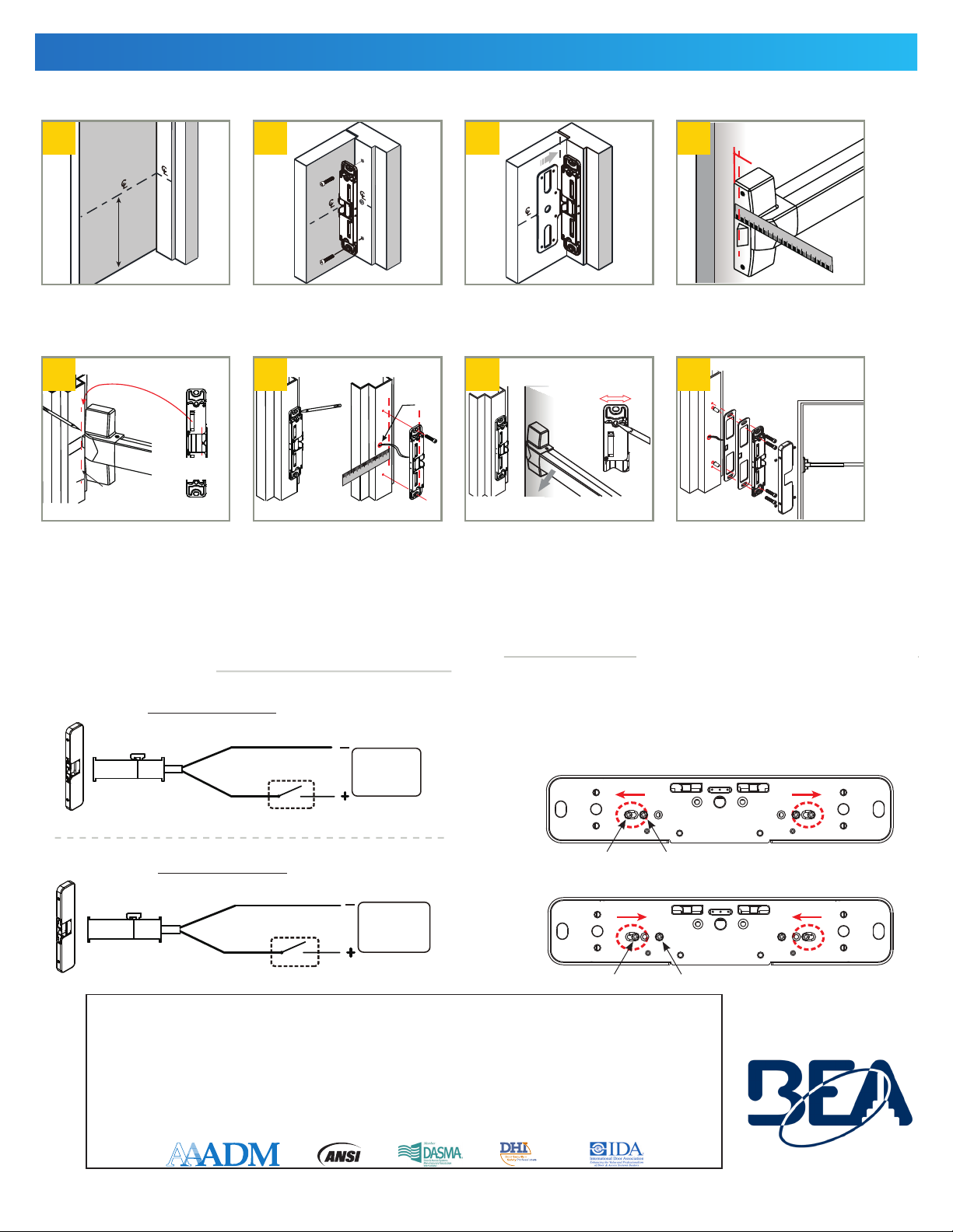
MOUNTING & WIRING
Steps 1 –3 only need to be performed if there was NOT an existing exit device at the installation site.
BEA, Inc., the sensor manufacturer, cannot be held responsible for incorrect installations or incorrect adjustments of the sensor/device; therefore, BEA,
Inc. does not guarantee any use of the sensor/device outside of its intended purpose.
BEA, Inc. strongly recommends that installation and service technicians be AAADM-certified for pedestrian doors, IDA-certified for doors/gates, and
factory-trained for the type of door/gate system.
Installers and service personnel are responsible for executing a risk assessment following each installation/service performed, ensuring that the sensor/
device system installation is compliant with local, national, and international regulations, codes, and standards.
Once installation or service work is complete, a safety inspection of the door/gate shall be performed per the door/gate manufacturer’s recommendations
and/or per AAADM/ANSI/DASMA guidelines (where applicable) for best industry practices. Safety inspections must be performed during each service
call – examples of these safety inspections can be found on an AAADM safety information label (e.g. ANSI/DASMA 102, ANSI/DASMA 107).
Verify that all appropriate industry signage and warning labels are in place.
BEA, INC. INSTALLATION/SERVICE COMPLIANCE EXPECTATIONS
T
ech Support & Customer Service: 1-800-523-2462 | General Tech Questions: [email protected] | Tech Docs: www.BEAsensors.com©BEA | Original Instructions
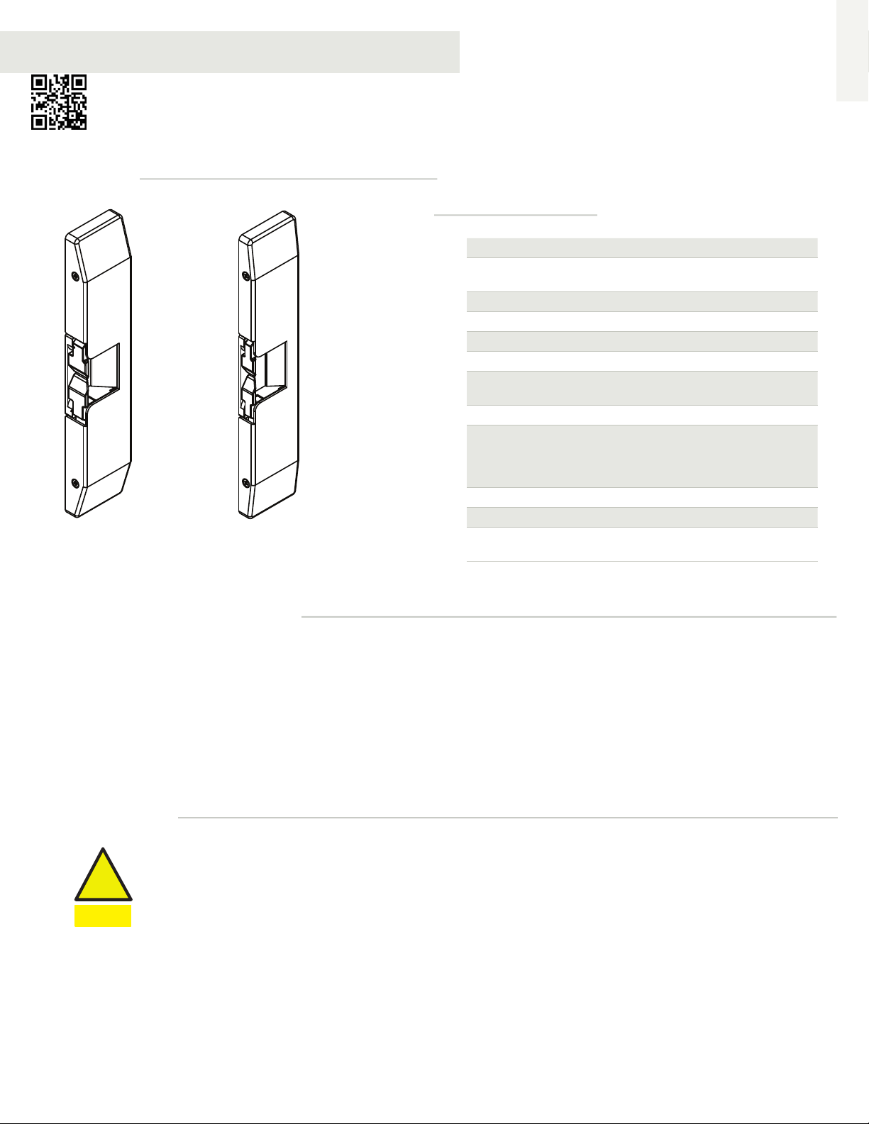
75.5012.01 RIM EXIT ELECTRIC STRIKE 20210121
Measure 39 13⁄16” (1011mm) from
the finished floor and mark strike
centerline on the door. Transfer
centerline to frame.
Close the door and mark the latch
position on the frame. The latch
position line will correspond with
the inside of the strike keeper as
shown.
Align the strike on the centerline
and mark two slotted holes. Drill
holes and secure strike to frame.
Position the strike on the frame
according to the marks. Using the
strike as a template, mark and
drill a cable access hole and two
mounting holes. Loosely mount the
strike with Phillips flathead screws.
Align template on centerline and
against strike.
Measure the exit device latch
position on the door.
Check latchbolt interaction and
adjust the strike horizontally until
the door latches properly, then
tighten the two mounting screws
and mark remaining screw holes.
Remove the strike and drill marked holes.
Wire accordingly. Insert the blind nuts
into the holes and re-install the strike. If
necessary, add spacers to adjust the gap
between the strike and exit device. Secure
the strike with the hex-socket, cap screws
into the blind nuts.
Connection Diagram Fail-safe / Fail-secure Reversible
12 VDC
white
control device
black
(not polarity sensitive)
24VDC
control device
(not polarity sensitive)
red
black
12 VDC operation
24 VDC operation
Remove locking screw, loosen, slide and tighten sliding screw.
Reinsert and tighten locking screw to the desired fail-safe or
fail-secure setting.
Fail-Safe: screws locked AWAY from each other
Fail-Secure: screws locked TOWARDS each other
locking screw
locking screw
sliding screw
sliding screw