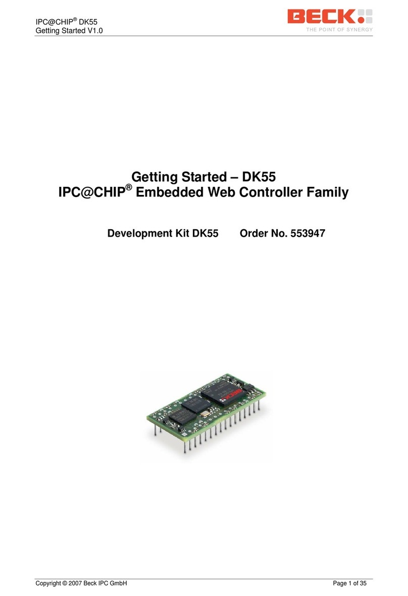
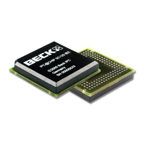
Beck IPC@CHIP Series User manual

IPC@CHIP DK41 / DK51
Getting Started V2.2
© 2000-2004 Beck IPC GmbH Page 1 of 61
Getting Started
IPC@CHIP Embedded Web Controller Family
Development Kit DK41 Order No. 20041011
Development Kit DK51 Order No. 538823

IPC@CHIP DK41 / DK51
Getting Started V2.2
© 2000-2004 Beck IPC GmbH Page 2 of 61
Table of Contents
1 INTRODUCTION................................................................................................................................ 3
SYSTEM START-UP............................................................................................................................... 4
2.1 DK40 DEVELOPMENT BOARD START-UP (SC12)............................................................................ 4
2.1.1 What do we need to get started?....................................................................................... 4
2.1.2 Step 1 – Switching on the DK40 Development Board....................................................... 5
2.1.3 Step 2 – Setting up the serial communication ................................................................... 6
2.1.4 Step 3 – Setting up the Ethernet communication .............................................................. 7
2.1.5 Step 4 – Downloading the DK40 Online demo program ................................................. 11
2.1.6 Step 5 – Operating the Demo program ........................................................................... 14
2.2 DK50 DEVELOPMENT BOARD START-UP (SC13).......................................................................... 15
2.2.1 What do we need to get started?..................................................................................... 15
2.2.2 Step 1 – Switching on the DK50 Development Board..................................................... 16
2.2.3 Step 2 – Setting up the serial communication ................................................................. 17
2.2.4 Step 3 – Setting up the Ethernet communication ............................................................ 18
2.2.5 Step 4 – Downloading the DK50 Online demo program ................................................. 22
2.2.6 Step 5 – Operating the Demo program ........................................................................... 25
2.2.7 Step 6 – Configuring the CF Card ................................................................................... 26
2.3 DK50 DEVELOPMENT BOARD START-UP (SC11).......................................................................... 29
2.3.1 What do we need to get started?..................................................................................... 29
2.3.2 Step 1 – Switching on the DK50 Development Board..................................................... 30
2.3.3 Step 2 – Setting up the serial communication ................................................................. 31
2.3.4 Step 3 – Setting up the PPP communication................................................................... 32
2.3.5 Step 4 – Downloading the DK50 Online demo program ................................................. 41
2.3.6 Step 5 – Operating the Demo program ........................................................................... 44
2.3.7 Step 6 – Configuring the CF Card ................................................................................... 45
3 INFORMATION FOR ADVANCED USERS ..................................................................................... 48
3.1 MANUAL IP CONFIGURATION VIA THE TERMINAL ........................................................................... 48
3.2 IPC@CHIP @CHIP-RTOS ....................................................................................................... 49
3.2.1 Updates............................................................................................................................ 49
3.2.2 Downloading RTOS updates ........................................................................................... 50
3.2.3 CHIP.INI configuration file ............................................................................................... 51
3.2.4 The command shell ......................................................................................................... 52
3.2.5 The PPP Server/Client..................................................................................................... 52
3.2.6 The HTTP Web Server .................................................................................................... 53
3.3 WRITING EXECUTION PROGRAMS FOR THE IPC@CHIP................................................................ 54
3.3.1 Introduction ...................................................................................................................... 54
3.3.2 IPC@CHIP API documentation ....................................................................................... 54
3.3.3 IPC@CHIP example programs........................................................................................ 54
3.3.4 Program debugging ......................................................................................................... 57
3.3.5 Stripping debug information from executables prior to download ................................... 59
4 APPENDIX ....................................................................................................................................... 60
4.1 BASICS OF IP NETWORKING ......................................................................................................... 60
4.2 WHERE TO FIND OTHER INFORMATION ON THE IPC@CHIP ........................................................... 61
4.3 WHERE TO GET SUPPORT ............................................................................................................ 61
4.4 USEFUL WEB LINKS ..................................................................................................................... 61
4.5 ORDER NUMBERS........................................................................................................................ 61

IPC@CHIP DK41 / DK51
Getting Started V2.2
© 2000-2004 Beck IPC GmbH Page 3 of 61
1 Introduction
Congratulations on purchasing your IPC@CHIP Development Kit. The Development Kits are complete
ready-to-use development systems for building applications based on the Embedded Web Controller
IPC@CHIP SC12 and IPC@CHIP SC13. Both products run with the @CHIP-RTOS operating system,
which includes features like a real-time kernel that is capable of running common DOS applications
concurrently, a full TCP/IP stack with a UDP/TCP socket interface, DHCP, FTP, PPP, Telnet, Web
server etc.
The DK41 is the Development Kit for the Embedded Web Controller SC12. The Kit contains: a DK40
Evaluation Module, an Embedded Web Controller SC12 and an SM14 programming cable. Available
as an option: a PSE4 power supply unit and the Borland C++ Software Development Environment:
DK41 Development Kit
The DK51 is the Development Kit for the new Embedded Web Controller SC13. The Kit contains
within a systainer case a DK50 Development Board, an SC13 Embedded Controller, the Borland C++
Software Development Environment, a serial cable and an AC power supply unit with interchangeable
plugs:
DK51 Development Kit
The Development Kits contain both hardware and software components required for a basic
development. This document provides a step-by-step guide on how to put the Embedded Web
Controllers SC12 and SC13 into operation, and concentrates on a system level start-up. For more
information about hardware and software functionality please also read the IPC@CHIP API
Documentation and IPC@CHIP Hardware Manual.

IPC@CHIP DK41 / DK51
Getting Started V2.2
© 2000-2004 Beck IPC GmbH Page 4 of 61
2 System Start-up
2.1 DK40 Development Board Start-up (SC12)
2.1.1 What do we need to get started?
•The DK41 Development Kit consisting of:
•DK40 Development Board
•Embedded Web Controller SC12
•Null-modem cable
•SM14 RS232 to TTL converter
•A PC running Windows 95/98/NT/2000/XP, with an Ethernet network interface
•Serial port on your PC
•Ethernet network with an available twisted pair connection for the DK40 Development Board
•A DC power supply (24 VDC will do fine)
•Windows HyperTerminal program
•Zip-files from the Beck Getting Started web site:
•FTP client TotalCommander as shareware
•CHIPTOOL Software
•DK40 Online demo software package
The Getting Started web site contains all the tools and programs required to put the Development Kit
into operation. The FTP client is a shareware program. For more details please read the online
documentation of this tool. You can use any FTP program which provides file transfer support.
Be aware, that the Embedded Controller SC12 and DK40 Development
Board are Electrostatic Sensitive Devices. Observe general precautions
for handling.

IPC@CHIP DK41 / DK51
Getting Started V2.2
© 2000-2004 Beck IPC GmbH Page 5 of 61
2.1.2 Step 1 – Switching on the DK40 Development Board
The DK40 Development Board is an evaluation platform for the Embedded Controller SC12. It
provides two serial ports, an Ethernet interface, eight digital I/O, a ‘link/traffic’ LED, a free
programmable LED and a switching DC/DC converter (15 ... 30V -> 5 V).
1
2
3
4
56
7
8910
Free programmable user LED
1
Combined link/traffic/reset LED
2
Network transformer for twisted pair
3
Interference capacitor4
Socket strip with screw terminal for
voltage supply and combined
inputs/outputs
5
Control LEDs for combined
inputs/outputs
6
IPC @CHIP SC10/SC11/SC12
7
Twisted pair network connection
for 10Base T
8
EXT interface
9
COM interface10
First of all, you have to place the SC12 into the socket inside the DK40. The small dot on the top of the
SC12 diagonally opposite to the BECK logo indicates pin 1. The notch in the socket indicates the
position of pin 1 in the socket. Please also refer to the drawing of the DK40 and make sure you insert
the chip with the correct orientation.
Connect the power supply (24 VDC) to the DK40 socket strip. GND must be connected to the pin
marked "-". +24 VDC must be connected to the pin marked '+'.

IPC@CHIP DK41 / DK51
Getting Started V2.2
© 2000-2004 Beck IPC GmbH Page 6 of 61
2.1.3 Step 2 – Setting up the serial communication
Please connect the null modem cable and SM14 converter from the DK41 Development Kit to your
PC’s COM port and to the COM port of the DK40 (10).
You then need to launch the Windows HyperTerminal program. If it's not part of your current Windows
installation, you should install the application from your Windows CD.
Start the HyperTerminal program. Enter a name for the new connection (e.g. DK40 Dev Board).
Choose the connection via the COM port of your PC.
Set the communication parameters to 19200 baud, 8 data bits, no parity, one stop bit, no handshake.
The HyperTerminal program now connects the PC with the DK40. Press Enter when the terminal
window is opened to see the ‘A:>’ prompt for the drive A: on the Embedded Controller. Enter the
command ‘dir’ and you will see the root directory of the Embedded Controller.
The Embedded Controller is factory shipped with the two graphics files "BECK.GIF" and "CHIP.GIF"
on the drive.

IPC@CHIP DK41 / DK51
Getting Started V2.2
© 2000-2004 Beck IPC GmbH Page 7 of 61
2.1.4 Step 3 – Setting up the Ethernet communication
The following chapter describes the set-up of the Ethernet communication. Before moving on, you
must decide if you want to use either DHCP1or fixed addressing. With DHCP, the IPC@CHIP
retrieves a valid IP configuration from a DHCP server. With fixed addressing, you define the IP
address, network mask and an optional gateway2.
The default configuration for the IPC@CHIP is DHCP since this will ensure that the IPC@CHIP adapts
to an existing network if this network has a DHCP server. If you do not have a DHCP server, the
IPC@CHIP will not disturb the operation of your network. We cannot ship with a fixed IP configuration
since we have no knowledge of your network configuration.
a) DHCP IP configuration: (default setting)
In a network supporting DHCP the DK40 retrieves a valid IP configuration from a DHCP server
automatically.
Connect the DK40 to your Ethernet network hub or switch with a standard twisted pair cable. Reset
your DK40 with power off and power on. On the terminal window (HyperTerminal) you will see the
output from the start-up procedure. Here you will see the serial number, @CHIP-RTOS version, build
date and other start-up information. If an IP configuration could be successfully received from the
DHCP server, this IP configuration will be displayed at the end of the start-up output messages. In the
event of an error, the message “DHCP request failed” will be output after a timeout of several seconds.
@CHIP-RTOS
Copyright (c) BECK IPC GmbH 1999-2004
Copyright (c) Elmic Systems, Inc. 1999-2004
Target=SC12 Serialnumber=020C2
Bootstrap version V2.24
@CHIP-RTOS version SC12 V1.10 LARGE
Build: Mar 22 2004
Serial EXT Port using DMA receive, IRQ send
Serial COM Port using DMA receive, IRQ send
Starting TCPIP
Init network
Ethernet packet interface
Config server
FTP server
Web server
Telnet server
Ext. disk interface.
TCPIP device driver API
Software SPI API
@CHIP-RTOS boot successfully finished
Leased IP 172.30.11.228
Mask 255.255.240.0
Gateway 172.30.0.2
Leasing time: 3600 secs
1DHCP: "Dynamic Host Configuration Protocol“.
2Gateway: "Computers that interconnect two networks and pass packets from one to the other are called internet gateways or
internet routers."

IPC@CHIP DK41 / DK51
Getting Started V2.2
© 2000-2004 Beck IPC GmbH Page 8 of 61
b) Manual IP configuration:
If your local network does not include a DHCP server, you must assign an IP address manually.
Please contact your network administrator for details about your local network. Your administrator can
give you a valid IP address setting for your network. A brief introduction to IP basics in TCP/IP
networks is given in the Appendix.
For Ethernet connection you can use two alternatives:
1. You have a network with multiple clients. The network uses hubs and/or switches. In this case,
you need a regular twisted pair Ethernet cable running from one of your hubs to the DK40.
2. You have a network consisting of only two devices (your PC and the DK40) without a hub or a
‘switch’. In this case you need a so-called ‘cross over’ twisted pair Ethernet cable.
To review or change the IP configuration, you can either access the IPC@CHIP using a terminal
program connected to the COM port of the IPC@CHIP (see chapter "Manual IP Configuration via the
Terminal"), or use the ‘CHIPTOOL’ software that communicates with the IPC@CHIP over the
Ethernet. The method using the CHIPTOOL software is described below.
The Windows application CHIPTOOL can be used to manage IPC@CHIP products. CHIPTOOL
provides network configuration and software updates of IPC@CHIPs during the development and
production process of IPC@CHIP-based products. It is also useful for third-party customers to
manage their IPC@CHIP-based products. This tool can be downloaded from the IPC@CHIP home
page: http://www.beck-ipc.com/ipc in the download area. For more details about CHIPTOOL take a
look at the integrated help documentation of the application.
Launch the CHIPTOOL software. To verify the current IP configuration, take a look at the main window
of the CHIPTOOL application. This table will show all IPC@CHIP targets it finds on this section of the
local network. The scan is repeated continuously. New devices that are switched on will be found
within seconds. The IPC@CHIP will be displayed as “not configured” if a DHCP server is not available.

IPC@CHIP DK41 / DK51
Getting Started V2.2
© 2000-2004 Beck IPC GmbH Page 9 of 61
Select the menu option ‘Chip’ and ‘IP Config’. Fill in the dialog as illustrated below:
The serial number data shown here is just an example. At ‘Serial number or MAC-ID’ you enter the
serial number of the IPC@CHIP that you want to configure.
The serial number is a 5 digit hexadecimal number (valid hexadecimal digits: 0..9 and A..F) reported to
the terminal at start-up. The serial number is also displayed in the main window of CHIPTOOL next to
every IPC@CHIP detected and is also printed on a label on every IPC@CHIP.
Since SC12@CHIP-RTOS version 1.10Beta, it is also possible to enter the MAC-address (we use this
address also as a unique ID3to identify IPC@CHIPs) of the internal Ethernet controller. This ID is
shown at the column ID of the CHIPTOOL’s network scan window.
In the area ‘Chip IP configuration’ you enter the IP address, network mask and optionally the gateway
address.
Now click the ‘Config’ button. This will send a UDP broadcast datagram over the network, which
includes the serial number of the IPC@CHIP and the new IP configuration.
Check in the main window of CHIPTOOL that the IP configuration you have entered is correctly
displayed.
The IP configuration information is now stored in the file ‘CHIP.INI’ on the flash disk.
3This address is unique because Ethernet controllers must have a world-wide unique 6 byte address.

IPC@CHIP DK41 / DK51
Getting Started V2.2
© 2000-2004 Beck IPC GmbH Page 10 of 61
In the terminal window (HyperTerminal), press the ‘Enter’ key once until you see the ‘A:>’ prompt.
Enter the command ‘ipcfg’ followed by the ‘Enter’ key. The output will show the current IP configuration
of all the supported device interfaces. For example:
A:\>ipcfg
Device = NE2000
Type = ETH
Idx = 2
IP = 192.168.200.1
Netmask = 255.255.255.0
DHCP = 0
Mac = 00 30 56 F0 20 C2
Device = LOOPBACK
Type = LPK
Idx = 1
IP = 127.0.0.1
Netmask = 255.255.255.255
Gateway = 192.168.200.10
The figure above shows the IP configuration of the Ethernet device and of the “Internal loopback
device”.

IPC@CHIP DK41 / DK51
Getting Started V2.2
© 2000-2004 Beck IPC GmbH Page 11 of 61
2.1.5 Step 4 – Downloading the DK40 Online demo program
The following describes how to download files to the IPC@CHIP and put the DK40 online demo into
operation on your DK40.
The RTOS of the IPC@CHIP features an FTP server for transferring files. FTP stands for File Transfer
Protocol and has become a standard for transferring files over TCP/IP networks. All you need to
transfer a file from or to the IPC@CHIP is an FTP client. Your Windows system only provides an FTP
client with a command line interface. Clearly, a graphical user interface, such as with the WS-FTP or
TotalCommander, is much more user-friendly.
The following explains the data transfer procedure using the TotalCommander shareware program.
Install and start TotalCommander. In the left-hand pane select the path where the DK40 online demo
files are located. Switch to the right-hand pane and choose FTP Connect from the Net menu. Click
“New connection” in the dialog that opens.
Under "Session" enter a name for the connection, such as “DK40 Dev Board”. The IP address of the
IPC@CHIP must be specified in the “Host name” field. To connect to the FTP server, you need also a
user name and a password. For the IPC@CHIP you use ‘ftp’ as user name and also ‘ftp’ as password.
These are default settings that can be changed at a later time.
Click OK to confirm and close the dialog. In the previous dialog select the new connection and click
“Connect".

IPC@CHIP DK41 / DK51
Getting Started V2.2
© 2000-2004 Beck IPC GmbH Page 12 of 61
You should now be connected to the FTP server of the IPC@CHIP and the drive content of the
IPC@CHIP should now be visible in the right-hand pane of TotalCommander.
Select all files and subfolders in the path of the DK40 Online Demo apart from the CHIP.INI file, in
case this is already present on the IPC@CHIP. This will ensure that you do not overwrite the IP
configuration you have entered beforehand. If the CHIP.INI file is not present on the IPC@CHIP, this
means that you have not carried out a manual IP configuration and have selected the method using
DHCP. In this case, copy the CHIP.INI file to the IPC@CHIP together with the other files selected.
Click the “F5 Copy” button to copy the files to drive A: of the IPC@CHIP.
If you have not copied the CHIP.INI file with the other files, now select the CHIP.INI file on the PC and
click the “F3 View” button to view the content of the file. Select all the text apart from the section [IP]
and copy it to the Clipboard with CTRL+C. Then close the window.

IPC@CHIP DK41 / DK51
Getting Started V2.2
© 2000-2004 Beck IPC GmbH Page 13 of 61
Now choose the CHIP.INI file on the IPC@CHIP and click “F4 Edit” to edit the file.
Paste the content of the Clipboard into the file after the IP section with CTRL+V.
Save the file and close the editor. In the dialog prompt that follows, you must then confirm that you
wish to upload the modified CHIP.INI file onto the IPC@CHIP. You then have to confirm that you wish
to overwrite the existing file.
You can close the FTP connection by clicking the “Disconnect” button once all files have been
transferred.
The DK40 must be restarted in order to activate the demo. To do this, switch the power off and on.

IPC@CHIP DK41 / DK51
Getting Started V2.2
© 2000-2004 Beck IPC GmbH Page 14 of 61
2.1.6 Step 5 – Operating the Demo program
Start your Internet browser and enter the IP address of your IPC@CHIP in the address bar. The start
page of the DK40 Online Demo will appear. Please choose the Java Applet example from the start
page. The security settings of your browser must allow the use of Java applets.
A Java applet is then loaded that visually represents the digital I/Os of the DK40. Click the fields
marked 7 to 0 in order to switch the outputs of the DK40 on and off.

IPC@CHIP DK41 / DK51
Getting Started V2.2
© 2000-2004 Beck IPC GmbH Page 15 of 61
2.2 DK50 Development Board Start-up (SC13)
2.2.1 What do we need to get started?
•The DK51 Development Kit consisting of:
•DK50 Development Board
•Embedded Web Controller SC13 (on the DK50)
•Power supply unit
•Null-modem cable
•Borland C++ Software Development Environment
•A PC running Windows 95/98/NT/2000/XP, with an Ethernet network interface
•Serial port on your PC
•Ethernet network with an available twisted pair connection for the DK50 Development Board
•Windows HyperTerminal program
•Optional: Compact Flash Card, if you want to configure the CF Interface (not needed for start-up)
•Zip-files from the Beck Getting Started web site:
•FTP client TotalCommander as shareware
•CHIPTOOL Software
•DK50 Online demo software package
•Compact Flash Card Driver EXTIDE.EXE
The Getting Started web site contains all the tools and programs required to put the Development Kit
into operation. The FTP client is a shareware program. For more details please read the online
documentation of this tool. You can use any FTP program which provides file transfer support.
Be aware, that the Embedded Controller SC13 and DK50 Development
Board are Electrostatic Sensitive Devices. Observe general precautions
for handling.

IPC@CHIP DK41 / DK51
Getting Started V2.2
© 2000-2004 Beck IPC GmbH Page 16 of 61
2.2.2 Step 1 – Switching on the DK50 Development Board
The DK50 Development Board is an evaluation platform for the Embedded Controller SC13 and SC11.
Among other functions, it provides two serial ports, an Ethernet interface, eight digital I/O, a ‘traffic’
LED4, CompactFlash Socket and a switching DC/DC converter.
The AC power supply is delivered with country specific AC adapters. Please choose the right adapter
for your country. Then connect the AC power supply to your main supply and to the DK50
Development Board. The Power LED (7) will light up and Traffic LED will light up for less than half a
second.
4Please note: The SC12 has a combined Ethernet Link/Traffic function. The SC13 has only Ethernet Traffic function.

IPC@CHIP DK41 / DK51
Getting Started V2.2
© 2000-2004 Beck IPC GmbH Page 17 of 61
2.2.3 Step 2 – Setting up the serial communication
Please connect the null modem cable from the DK51 Development Kit to your PC’s COM port and to
the COM port of the DK50 (5).
Next, you need the Windows HyperTerminal program. If it's not part of your current Windows
installation, you should install the application from your Windows CD.
Start the HyperTerminal program. Enter a name for the new connection (e.g. DK50 Dev Board).
Choose the connection via the COM port of your PC.
Set the communication parameters to 19200 baud, 8 data bits, no parity, one stop bit, no handshake.
The HyperTerminal program now connects the PC with the DK50. Press Enter when the terminal
window is opened to see the ‘A:>’ prompt for the drive A: on the Embedded Controller. Enter the
command ‘dir’ and you will see the root directory of the Embedded Controller.
The Embedded Controller is factory shipped with the two graphics files "BECK.GIF" and "CHIP.GIF"
on the drive.

IPC@CHIP DK41 / DK51
Getting Started V2.2
© 2000-2004 Beck IPC GmbH Page 18 of 61
2.2.4 Step 3 – Setting up the Ethernet communication
The following chapter describes the set-up of the Ethernet communication. Before moving on, you
must decide if you want to use either DHCP5or fixed addressing. With DHCP, the IPC@CHIP
retrieves a valid IP configuration from a DHCP server. With fixed addressing, you define the IP
address, network mask and an optional gateway6.
The default configuration for the IPC@CHIP is DHCP since this will ensure that the IPC@CHIP adapts
to an existing network if this network has a DHCP server. If you do not have a DHCP server, the
IPC@CHIP will not disturb the operation of your network. We cannot ship with a fixed IP configuration
since we have no knowledge of your network configuration.
a) DHCP IP configuration: (default setting)
In a network supporting DHCP the DK50 retrieves a valid IP configuration from a DHCP server
automatically.
Connect the DK50 to your Ethernet network hub or switch with a standard twisted pair cable. Press the
Reset button (8) of your DK50. On the terminal window (HyperTerminal) you will see the output from
the start-up procedure. Here you will see the serial number, @CHIP-RTOS version, build date and
other start-up information. If an IP configuration could be successfully received from the DHCP server,
this IP configuration will be displayed at the end of the start-up output messages. In the event of an
error, the message “DHCP request failed” will be output after a timeout of several seconds.
@CHIP-RTOS
Copyright (c) BECK IPC GmbH 1999-2004
Copyright (c) Elmic Systems, Inc. 1999-2004
Target=SC13 Serialnumber=00017
Bootstrap version V2.25
@CHIP-RTOS version SC13 V1.00 LARGE
Build: Mar 22 2004
Serial EXT Port using DMA receive, IRQ send
Serial COM Port using DMA receive, IRQ send
Starting TCPIP
Init network
Ethernet packet interface
Config server
FTP server
Web server
Telnet server
Ext. disk interface.
TCPIP device driver API
Software SPI API
@CHIP-RTOS boot successfully finished
Leased IP 172.30.11.228
Mask 255.255.240.0
Gateway 172.30.0.2
Leasing time: 3600 secs
5DHCP: "Dynamic Host Configuration Protocol“.
6Gateway: "Computers that interconnect two networks and pass packets from one to the other are called internet gateways or
internet routers."

IPC@CHIP DK41 / DK51
Getting Started V2.2
© 2000-2004 Beck IPC GmbH Page 19 of 61
b) Manual IP configuration:
If your local network does not include a DHCP server, you must assign an IP address manually.
Please contact your network administrator for details about your local network. Your administrator can
give you a valid IP address setting for your network. A brief introduction to IP basics in TCP/IP
networks is given in the Appendix.
For Ethernet connection you can use two alternatives:
1. You have a network with multiple clients. The network uses hubs and/or switches. In this case,
you need a regular twisted pair Ethernet cable running from one of your hubs to the DK50.
2. You have a network consisting of only two devices (your PC and the DK50) without a hub or a
‘switch’. In this case you need a so-called ‘cross over’ twisted pair Ethernet cable.
To review or change the IP configuration, you can either access the IPC@CHIP using a terminal
program connected to the COM port of the IPC@CHIP (see chapter "Manual IP Configuration via the
Terminal"), or use the ‘CHIPTOOL’ software that communicates with the IPC@CHIP over the
Ethernet. The method using the CHIPTOOL software is described below.
The Windows application CHIPTOOL can be used to manage IPC@CHIP products. CHIPTOOL
provides network configuration and software updates of IPC@CHIPs during the development and
production process of IPC@CHIP-based products. It is also useful for third-party customers to
manage their IPC@CHIP-based products. This tool can be downloaded from the IPC@CHIP home
page: http://www.beck-ipc.com/ipc in the download area. For more details about CHIPTOOL take a
look at the integrated help documentation of the application.
Launch the CHIPTOOL software. To verify the current IP configuration, take a look at the main window
of the CHIPTOOL application. This table will show all IPC@CHIP targets it finds on this section of the
local network. The scan is repeated continuously. New devices that are switched on will be found
within seconds. The IPC@CHIP will be displayed as “not configured” if a DHCP server is not available.

IPC@CHIP DK41 / DK51
Getting Started V2.2
© 2000-2004 Beck IPC GmbH Page 20 of 61
Select the menu option ‘Chip’ and ‘IP Config’. Fill in the dialog as illustrated below :
The serial number data shown here is just an example. At ‘Serial number or MAC-ID’ you enter the
serial number of the IPC@CHIP that you want to configure.
The serial number is a 5 digit hexadecimal number (valid hexadecimal digits: 0..9 and A..F) reported to
the terminal at start-up. The serial number is also displayed in the main window of CHIPTOOL next to
every IPC@CHIP detected and is also printed on a label on every IPC@CHIP.
Since SC13@CHIP-RTOS version 0.91Beta, it is also possible to enter the MAC-address (we use this
address also as a unique ID7to identify IPC@CHIPs) of the internal Ethernet controller. This ID is
shown at the column ID of the CHIPTOOL’s network scan window.
In the area ‘Chip IP configuration’ you enter the IP address, network mask and optionally the gateway
address.
Now click the ‘Config’ button. This will send a UDP broadcast datagram over the network, which
includes the serial number of the IPC@CHIP and the new IP configuration.
Check in the main window of CHIPTOOL that the IP configuration you have entered is correctly
displayed.
The IP configuration information is now stored in the file ‘CHIP.INI’ on the flash disk.
7This address is unique, because Ethernet controllers must have a world-wide unique 6 byte address.
This manual suits for next models
2
Table of contents
Other Beck Controllers manuals
Popular Controllers manuals by other brands
Alinco
Alinco EJ-S41U instruction manual
Damega
Damega Intel Siren Installation instructions manual
Neptronic
Neptronic BM000N Specification & installation instructions

Norac
Norac UC4+ installation manual

Pentair
Pentair GOYEN IS Series Products Installation Instructions
HEROSE
HEROSE 4186 Series Original Operating and Installation Instructions
