Beck IPC@CHIP DK55 User manual

IPC@CHIP®DK55
Getting Started V1.0
Getting Started – DK55
IPC@CHIP®Embedded Web Controller Family
Development Kit DK55 Order No. 553947
Copyright © 2007 Beck IPC GmbH Page 1 of 35

IPC@CHIP®DK55
Getting Started V1.0
Table of Contents
1INTRODUCTION.................................................................................................. 3
2SYSTEM START-UP............................................................................................ 3
2.1 WHAT DO WE NEED TO GET STARTED? .................................................................................. 3
2.2 STEP 1–SWITCHING ON THE DB54 DEVELOPMENT BOARD ................................................... 4
2.3 STEP 2–STARTING THE IPC@CHIPTOOL.......................................................................... 4
2.4 STEP 3–SETTING UP COMMUNICATION................................................................................. 5
2.4.1 Setting up the serial communication.................................................................................. 6
2.4.2 Setting up the Ethernet communication............................................................................. 7
2.4.2.1 IP address configuration via DHCP............................................................................ 8
2.4.2.2 IP address configuration by hand............................................................................... 8
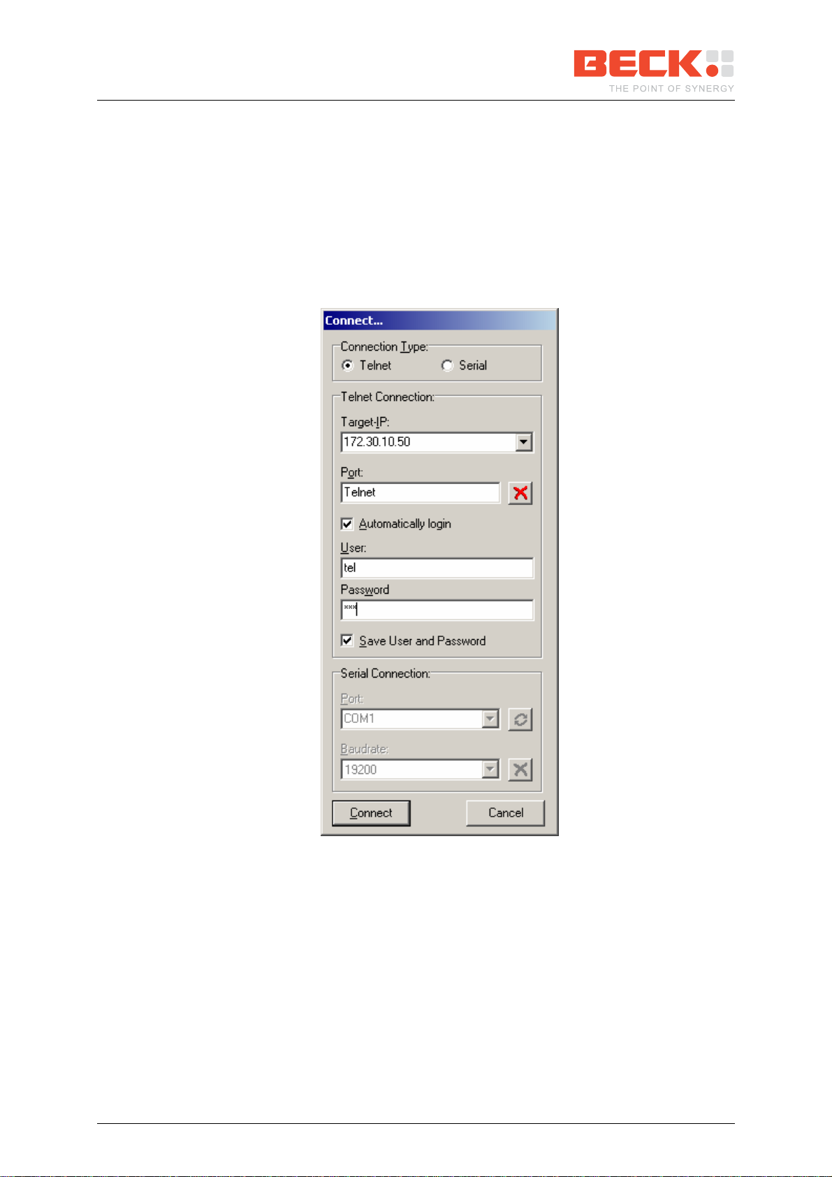
2.4.2.3 Using Telnet to access the shell............................................................................... 10
2.5 STEP 4–DOWNLOADING THE DB54 ONLINE DEMO PROGRAM.............................................. 11
2.6 STEP 5–OPERATING THE DEMO PROGRAM......................................................................... 13
2.7 STEP 6–SETTING UP USB CONNECTION ............................................................................ 15
2.8 STEP 7–CONFIGURING SD/MMC-CARD............................................................................ 18
3INFORMATION FOR ADVANCED USERS........................................................ 20
3.1 UPDATING THE @CHIP RTOS........................................................................................... 20
3.2 DEVELOPING SOFTWARE FOR YOUR IPC@CHIP®............................................................... 22
3.3 DEBUGGING YOUR IPC@CHIP®APPLICATIONS................................................................... 25
3.4 MISCELLANEOUS................................................................................................................ 29
3.4.1 The CHIP.INI configuration file........................................................................................ 29
3.4.2 The command shell ......................................................................................................... 29
3.4.3 The web server................................................................................................................ 30
3.4.4 The PPP server/client...................................................................................................... 30
3.4.5 New features in Paradigm C++ Beck IPC Edition ........................................................... 31
3.4.6 IPv4 Basics...................................................................................................................... 32
3.4.7 IPv4/v6 Dual Stack .......................................................................................................... 33
4APPENDIX - WHERE TO GET FURTHER INFORMATION............................... 34
4.1 GETTING STARTED............................................................................................................. 34
4.2 UPDATES,TOOLS AND EXAMPLES........................................................................................ 34
4.3 SUPPORT........................................................................................................................... 34
4.4 ORDER NUMBERS............................................................................................................... 34
Copyright © 2007 Beck IPC GmbH Page 2 of 35

IPC@CHIP®DK55
Getting Started V1.0
1 Introduction
Congratulations on purchasing your IPC@CHIP®DK55 Development Kit. The Development Kit
is a complete ready-to-use development system for building applications based on the
Embedded Web Controller IPC@CHIPP
®SC23. It runs with the @CHIP-RTOS operating
system, which includes features like a real-time kernel that is capable of running common DOS
applications concurrently, a full TCP/IP stack with a UDP/TCP socket interface, DHCP, FTP,
PPP, Telnet, Web server, APIs for CAN and USB controllers, etc.
The Development Kit contains both hardware and software components required for a basic
development. This document will introduce you to the several components of the DK55.
Chapter 2provides a step-by-step guide on how to put the DK55 into operation. Chapter 3
describes selected components of the DK55 for advanced users. Chapter 4points the way to
further information.
2 System Start-up
2.1 What do we need to get started?
- The Development Kit DK55 consisting of:
oDevelopment Board DB54
oEmbedded Web Controller
IPC@CHIP®SC23 (on the DB54)
oSerial null-modem cable
oUSB cable (A-to-Mini-B)
oEthernet patch cable (gray)
oEthernet cross-over cable (red)
oSecure Digital (SD) memory card
oPower supply unit
oParadigm C++ Beck IPC Edition CD
(including IPC@CHIPTOOL, DK55
startup documentation and drivers)
oThe enclosed CoDeSys CD is not
needed within the context of this manual.
- Personal Computer
oMicrosoft Windows 2000/XP Operating System
oEthernet network interface
oSerial port
oUSB interface
- Software from the enclosed Paradigm CD or the IPC@CHIP®Getting Started Website at
http://www.beck-ipc.com/gettingstarted
oDB54 Visualisation Demo
oDriver software
Be aware that the Embedded Controller SC23 and the
Development Board DB54 are electrostatic sensitive
components. Observe general precautions for handling.
Copyright © 2007 Beck IPC GmbH Page 3 of 35

IPC@CHIP®DK55
Getting Started V1.0
2.2 Step 1 – Switching on the DB54 Development Board
The Development Kit DK55 is designed to give you easy access to the functionality of the
IPC@CHIP®SC23, especially to its several interfaces like serial ports, Ethernet, digital I/O,
CAN, USB, etc.
The following graphic gives an overview of the most important components of the DB54 board.
The AC power supply is delivered with country specific AC adapters. Please choose the right
adapter for your country. Then connect the AC power supply to your main supply and to the
DB54 Development Board to power it. The Power LED will light up.
2.3 Step 2 – Starting the IPC@CHIPTOOL
The IPC@CHIPTOOL is your communication centre for all IPC@CHIP®-based products. It
provides functionality for finding IPC@CHIP®s on the network, configuring them, updating their
RTOS, transferring files and using their shell.
For installing IPC@CHIPTOOL at your PC execute the Chiptool setup program
CHIPTOOL_INSTALL.EXE from the Tools section of the CD or from the Getting Started
webpage. After the installation, you are able to start the IPC@CHIPTOOL application.
Copyright © 2007 Beck IPC GmbH Page 4 of 35

IPC@CHIP®DK55
Getting Started V1.0
In the main window you can see all IPC@CHIP®s that could be found on the network. The
table displays information such as serial number, name, IP configuration and RTOS version.
The main menu provides functionality such as the terminal and an FTP client which you will
need later on in the Getting Started process.
The following graphic shows only part of the main window.
The IPC@CHIPTOOL comes along with a detailed help. Simply press F1 in the main window
for further information.
If you’re running a firewall, make sure that it does not block any network functions of
IPC@CHIPTOOL such as Telnet, FTP or the scanning for IPC@CHIP®s.
2.4 Step 3 – Setting up communication
There are basically three ways to connect your DB54 to your PC: the serial interface, Ethernet
and USB.
The simplest connection type is the serial interface. Preferably use it to get access to the shell
of your IPC@CHIP®.
Ethernet communication is the most powerful. It may be used to access the shell via Telnet
and it’s the easiest way to transfer files to the IPC@CHIP®via FTP.
USB is an alternative to the serial interface. It provides nearly the same facilities as the serial
interface. Use it if your PC does not dispose of a serial interface. For USB connectivity a
separate software driver (USBTERM.EXE) is needed on the IPC@CHIP®. This driver should
already be preinstalled on the DB54 at factory setting. Setting up USB communication is
described later in chapter 2.7 of this document.
Copyright © 2007 Beck IPC GmbH Page 5 of 35

IPC@CHIP®DK55
Getting Started V1.0
2.4.1 Setting up the serial communication
To set up serial communication to your Development Kit DK55 you need the enclosed null-
modem cable.
1. Connect the null-modem cable to a free serial port of your PC and with the COM1 interface
of the DB54.
2. Choose Tools →Terminal from the IPC@CHIPTOOL main menu
3. In the connection dialog that now opens choose the following settings:
oConnection Type: Serial
oPort: The serial port of your PC that you connected the null-modem cable to, e.g.
COM1
oBaudrate: 19200
4. Press Connect to open the connection
5. You’re now connected to your IPC@CHIP®. Press Return to see the prompt.
Copyright © 2007 Beck IPC GmbH Page 6 of 35

IPC@CHIP®DK55
Getting Started V1.0
You may now use the commands of the @CHIP RTOS’ shell. The command DIR will, for
example, display a list of the files shipped on your IPC@CHIP®.
2.4.2 Setting up the Ethernet communication
Network communication is based on the TCP/IP protocol family. To be able to operate in a
TCP/IP network, your IPC@CHIP®needs to be assigned a valid and unambiguous IP address
and network mask. If you cannot figure out a proper IP address and network mask for your
IPC@CHIP®, please consult your network administrator.
There are two ways of assigning an IP address to your IPC@CHIP®SC23. You may either
configure it by hand or you may use DHCP to automatically assign IP settings. Of course you
will need a DHCP server to achieve the latter.
The default configuration for the IPC@CHIP®is using DHCP since this will ensure that the
IPC@CHIP®adapts to an existing network if this network disposes of a DHCP server. If your
network doesn’t possess a DHCP server, the IPC@CHIP®will not disturb the operation of your
network.
If you have a regular local network with several clients, connect the DB54’s Ethernet interface
to your Ethernet hub or switch using the enclosed twisted pair patch cable (gray) and go on to
section 2.4.2.1 or 2.4.2.2 depending on how you’d like to assign IP settings to your
IPC@CHIP®.
If you’re not connected to a network but want to connect the DB54 directly to your PC, you
have to use the enclosed cross-over twisted pair Ethernet cable (red) to plug the DB54’s
Ethernet interface to your PC’s Ethernet interface. Then go on to section 2.4.2.2.
Copyright © 2007 Beck IPC GmbH Page 7 of 35

IPC@CHIP®DK55
Getting Started V1.0
2.4.2.1 IP address configuration via DHCP
In a network supporting DHCP the IPC@CHIP®retrieves a valid IP configuration from a DHCP
server automatically.
Press the Reset button of your DB54. On the terminal window you will get displayed the boot
messages. Here you will see the serial number, @CHIP-RTOS version, build date and other
information. If an IP configuration could be successfully received from the DHCP server, this IP
configuration will be displayed at the end of the boot messages. In the event of an error, the
message DHCP request failed will be put out after a few seconds.
2.4.2.2 IP address configuration by hand
The easiest way to configure your IPC@CHIP®’s IP settings by hand is to use the functionality
of the IPC@CHIPTOOL software. In a network without DHCP server your IPC@CHIP®should
be displayed as Not configured since by default DHCP is enabled but no server could be
found.
Copyright © 2007 Beck IPC GmbH Page 8 of 35

IPC@CHIP®DK55
Getting Started V1.0
1. Right-click on your IPC@CHIP®.
2. Select IP configuration from the pop-up menu.
3. In the appearing dialog fill the fields IP Address, Network mask and, if necessary, Gateway
with appropriate values.
4. Uncheck Use DHCP and check Configure default ethernet interface.
5. Press the Config button to apply the new settings to your IPC@CHIP®.
6. Close the dialog and go back to the main window. It now shows the new IP configuration.
Copyright © 2007 Beck IPC GmbH Page 9 of 35

IPC@CHIP®DK55
Getting Started V1.0
2.4.2.3 Using Telnet to access the shell
Instead of using the serial terminal as described in section 2.4.1 to operate the shell of the
@CHIP RTOS you may use Telnet. Once the IP configuration of your IPC@CHIP®is
completed, simply perform the following steps:
1. Right-click on your IPC@CHIP®in the main window.
2. Select Telnet from the pop-up menu.
3. The appearing connection dialog is already filled with the right IP address. Complete the
fields User and Password (Automatically login has to be checked) with tel each and click
Connect.
4. You’re now logged in to your IPC@CHIP®. Press Return to see the prompt.
You may use telnet just like the serial terminal but the connection will be closed if the
IPC@CHIP®restarts.
Copyright © 2007 Beck IPC GmbH Page 10 of 35

IPC@CHIP®DK55
Getting Started V1.0
2.5 Step 4 – Downloading the DB54 Online demo program
First of all, you should download and extract the DB54DEMO.ZIP archive from the Getting
Started section of the CD or from the Getting Started webpage to the local hard drive of your
PC.
To transfer files to and from your IPC@CHIP®as easy as possible the IPC@CHIPTOOL
includes a simple FTP client. This can be used to connect to the @CHIP RTOS’ FTP server.
To open a connection, simply follow these steps:
1. Right-click on your IPC@CHIP®once again in the CHIPTOOL main window.
2. Select FTP from the pop-up menu.
3. Another connection dialog appears. It’s already filled with the respective IP address.
Complete the fields User and Password each with ftp.
4. Press the Connect button to establish the connection.
5. You now see the main window of the FTP client with your local drive on the left side and
the IPC@CHIP®’s flash drive on the right. The content of the chip’s drive may vary
depending on how you’ve configured your IP settings.
Copyright © 2007 Beck IPC GmbH Page 11 of 35

IPC@CHIP®DK55
Getting Started V1.0
You will now upload the DB54 Visualisation Demo that is further described in section 2.6.
6. In the left pane move to the directory where you have stored the Visualisation Demo.
7. Now change to the subdirectory Image of the extracted DB54 Visualisation Demo, which
contains all files that have to be deployed on the IPC@CHIP®.
8. Select all files in the image directory.
9. Right-click on one of the files and select Copy from the pop-up menu.
Copyright © 2007 Beck IPC GmbH Page 12 of 35

IPC@CHIP®DK55
Getting Started V1.0
The Visualisation Demo will now be copied to the IPC@CHIP®. If the FTP client notifies you
that a file named CHIP.INI or AUTOEXEC.BAT already exists, overwrite it. You will then have
to repeat the IP configuration described in section 2.4.2 after rebooting the chip. The file
CHIP.INI includes information such as the IP settings.
10. After all files have been copied, select Connection →Close from the menu.
11. Close the FTP client.
The FTP client provides much more functions than just transferring files. You may also create
and remove directories or edit text files situated on the IPC@CHIP®such as the CHIP.INI.
The handling should be quiet intuitive.
2.6 Step 5 – Operating the Demo program
To activate the Visualisation Demo you just transferred in section 2.5, reboot the IPC@CHIP®
by pressing the DB54’s Reset button. The Visualisation Demo is now accessible via the
IPC@CHIP®’s web server.
Right click on your IPC@CHIP®in the IPC@CHIPTOOL’s main window and select HTTP from
the pop-up menu. This will open your browser and show the main page of the IPC@CHIP®
which now is the Visualisation Demo.
The Visualisation Demo provides three techniques to visualise and modify the digital I/Os and
the LCD content of the DB54 – a Java Applet, a Flash Movie and a plain HTML/CGI Page.
The Java Applet as well as the Flash Movie show a picture of the DB54 plate. The I/Os
change their colour depending on their state. You may click the output LEDs in order to toggle
them. You may also enter some text that should be displayed on the LCD. To achieve this
click on the LCD picture, enter some text and press ENTER to transfer your text to the display.
Copyright © 2007 Beck IPC GmbH Page 13 of 35

IPC@CHIP®DK55
Getting Started V1.0
Of course the appropriate browser plug-ins have to be installed for the Java Applet or the
Flash Movie to work.
The HTML/CGI Page provides the same functionality but not graphically visualised.
Copyright © 2007 Beck IPC GmbH Page 14 of 35

IPC@CHIP®DK55
Getting Started V1.0
2.7 Step 6 – Setting up USB connection
If your PC does not dispose of a serial interface you can instead use the USB interface of the
DB54 to establish a serial connection. For USB connectivity a separate software driver
(USBTERM.EXE) is needed on the IPC@CHIP®. This driver should already be preinstalled on
the DB54 at factory setting. Anyway, please follow these steps to verify that the driver exists
and is listed inside the AUTOEXEC.BAT file of the IPC@CHIP®’s internal drive.
You need to copy and extract the USBTERM.ZIP archive from the Getting Started section of
the CD or from the Getting Started webpage to the local hard drive of your PC.
The extracted archive also contains the USB Terminal Emulation software.
1. If it does not already exist, copy the file USBTERM.EXE to the root directory of your
IPC@CHIP®using the @CHIPTOOL FTP client.
2. Right-click the file AUTOEXEC.BAT from the IPC@CHIP®’s flash drive. (If none exists,
create an empty file on your local drive and transfer it to the IPC@CHIP®.)
3. Select Edit from the pop-up menu.
4. An editor will open. If it does not already exist, add the filename USBTERM.EXE in a new
line. This will start the driver on boot.
5. Save the file and close the Editor. The file will automatically be reloaded to the chip.
6. Plug the USB Device Interface (Mini-B jack) of your Development Board DB54 into your
PC’s USB interface.
7. Reboot your DB54 by pressing its Reset button.
8. Your PC will notice a new USB device and show a message in the system tray.
9. Select in the first window of the wizard No, not this time and click the Next button.
Copyright © 2007 Beck IPC GmbH Page 15 of 35

IPC@CHIP®DK55
Getting Started V1.0
10. In the second window of the wizard select Install from a list or specific location (Advanced)
and click Next.
11. In the third dialog of the wizard choose Search for the best driver in these locations, check
Include this location in the search and enter below the path of the driver configuration file
USBTERM.INF. Click the Next button. Windows will now configure a virtual serial port.
Copyright © 2007 Beck IPC GmbH Page 16 of 35

IPC@CHIP®DK55
Getting Started V1.0
12. Close the wizard.
13. Open the Windows Device Manager by pressing the Windows-key + Break, switching to
the Hardware tab and pressing the button Device Manager.
14. Open the section Ports (COM & LPT) to check which COM port was assigned (e.g.
COM5).
15. Open the IPC@CHIPTOOL’s terminal and establish a connection via this COM port.
Please note that the Windows driver which handles virtual serial devices such as the
USB Terminal Emulation is not that robust. Avoid unplugging or restarting your DB54
while you have a connection established via the virtual COM port.
Copyright © 2007 Beck IPC GmbH Page 17 of 35

IPC@CHIP®DK55
Getting Started V1.0
2.8 Step 7 – Configuring SD/MMC-Card
To use the enclosed SD/MMC-Card you’ll need additional driver software on the DB54, which
should be preinstalled at factory setting. Anyway, please follow these steps to verify that the
driver exists and is listed inside the AUTOEXEC.BAT file of the IPC@CHIP®’s internal drive.
The driver is available from the Getting Started section of the CD or from the Getting Started
website. The driver program needed with SD/MMC-Cards is named EXTSD.EXE. Extract this
EXE from the EXTSD_DB54.ZIP archive.
Important: If you have downloaded the newest driver from the internet Getting Started
webpage, you probably need to recompile the driver project in the subdirectory
EXTSD\PARADIGM24. Disable the define DK60 and enable the define DB54 inside the
header file DEFINE.H and recompile the driver executable.
1. Open the IPC@CHIPTOOL FTP client. If it does not already exist, transfer the
EXTSD.EXE driver file to the root directory of your IPC@CHIP®.
2. Right-click the file AUTOEXEC.BAT from the IPC@CHIP®’s flash drive. (If none exists,
create an empty file on your local drive and transfer it to the IPC@CHIP®.)
3. Select Edit from the pop-up menu.
4. An editor will open. If it does not already exist, add the filename EXTSD.EXE in a new line.
This will start the driver on boot.
5. Save the file and close the Editor. The file will automatically be reloaded to the chip.
6. Close the FTP client.
7. Insert the respective card.
8. Reboot the DB54.
9. After booting the IPC@CHIP®will dispose of a drive B: which represents the content of
the card. You can access this drive from the shell or via FTP.
Use the command B: to change to the cards file system from the shell. In the FTP client
you may use the drive selection box to change to drive B.
Copyright © 2007 Beck IPC GmbH Page 18 of 35

IPC@CHIP®DK55
Getting Started V1.0
The EXTSD.EXE supports several command line options which are needed if you want to
mount a certain partition on the card or if you want to use several external disk drivers at once.
These command line options are described in the source code files of the corresponding
driver. These source code files may not be situated on the Getting Started CD. Please check
out the download section of our website in this case.
Note that there is also an EXTUSB.EXE driver for USB mass storage devices. This driver can
also be found on our website.
Copyright © 2007 Beck IPC GmbH Page 19 of 35

IPC@CHIP®DK55
Getting Started V1.0
3 Information for advanced users
3.1 Updating the @CHIP RTOS
You can download updates for your IPC@CHIP®’s RTOS from our website. These updates
may then easily be applied using IPC@CHIPTOOL.
1. Right-click on your IPC@CHIP®in the main window of @CHIPTOOL.
2. Select Program flash image from the pop-up menu.
3. The Program flash image dialog will appear.
4. Fill the field Load file with the path of the RTOS hex file. You may use the button on the
left to open a file browsing dialog.
You now have two options to load the update to your IPC@CHIP®. If you want to load the hex
file via the serial interface follow the steps on the left, if you prefer uploading it via Ethernet
follow the steps on the right. Loading the update via the serial interface should always work.
An Ethernet update presumes a running RTOS. So if your RTOS does not boot any more you
have to use the serial update.
5. Connect the COM1 interface of your
DB54 with a serial interface of your PC.
6. Select the respective COM port in the
port selection box.
7. Press the Start button in the section Use
RS-232 interface.
8. Press the Reset button of your DB54 to
reboot your IPC@CHIP®.
9. Wait for the update to complete.
5. Make sure your DB54 is connected to
your network.
6. Make sure one of the fields Serial
number or MAC-ID or IP address of
IPC@CHIP is filled correctly.
7. Press the Start button in the section Use
UDP/IP.
8. Wait for the update to complete.
If you are connected to the shell of your
IPC@CHIP®while performing an Ethernet
update, you will see a lot of ‘P’ characters
while the flash is programmed.
Copyright © 2007 Beck IPC GmbH Page 20 of 35
This manual suits for next models
1
Table of contents
Other Beck Controllers manuals
Popular Controllers manuals by other brands

S&C
S&C Micro-AT Operation

Blue Point Engineering
Blue Point Engineering Wizard - VIII Instruction

Chroma
Chroma 69200-1 user manual

MCDonald
MCDonald Electraflow installation instructions

Soyal
Soyal AR-727HB-RAY Series Installation and programming guide

TSUJI ELECTRONICS
TSUJI ELECTRONICS PM16C-16HW2 user manual