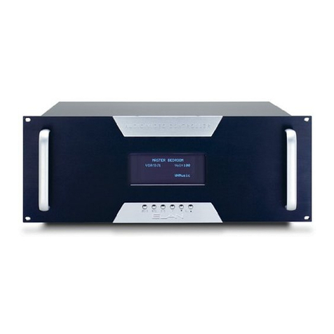
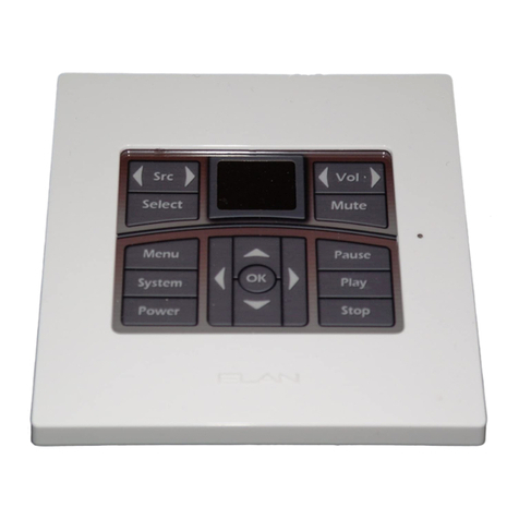
Elan VC VSE2 User manual

VSE
2
ELECTRONIC VOLUME CONTROL
100 WATT HIGH POWER

US
C
This ELAN Volume Control is NTRL certied to comply
with local building codes. Use Class 2 wiring and
methods per National Electrical Code NFPA70. Install in a
Listed electrical box.

ELAN INSTALLATION MANUAL
© 2013 Core Brands, LLC. • All rights reserved. Page 1
Contents
Introduction..............................................................3
Features.......................................................................3
Installation................................................................6
Rough-in......................................................................6
Wiring..........................................................................6
Speaker Connections..............................................7
RJ45 Connections .....................................................8
Sense Input Connections ..........................................9
IR Input .....................................................................10
Conguration/Applications........................................11
Stand-Alone Conguration..............................................11
ELAN System Congurations.................................13
ELAN S6 System Overview .............................................14
ELAN S8.6 System Overview...........................................15
ELAN S12 System Overview............................................16
ELAN Z•System Overview ..............................................17
PVSE Precision Panel..............................................18
PZ600 Precision Panel ..............................................19
ELAN S8.6/S12 Connections ...................................20
w/ COM2 and VSE2 ..................................................20
Override Connections ............................................21
ELAN System6..............................................................21
ELAN S8.6/S12 ............................................................21
ELAN Z•System ...........................................................22
ELAN Z•System Connections ................................23
Maximum Number Of VSE2s ...........................................23
Connecting Multiple VSE2s ...................................24

ELAN
Page 2 © 2013 Core Brands, LLC. • All rights reserved.
INSTALLATION MANUAL
Settings ....................................................................25
Default Volume Level......................................................25
Override Volume Level....................................................26
Sleep Mode ..................................................................27
Programmed Settings ....................................................28
Code Group..................................................................29
Variable Speed Ramping.................................................30
Volume Jumps ..............................................................31
On Default Volume Check ...............................................32
Sense Input .................................................................33
Talkback LED ...............................................................34
Factory Default..............................................................35
Impedance Match Settings.....................................35
Operation..................................................................37
Turning the VSE2 ON .....................................................37
Turning the VSE2 OFF ........................................................38
Controlling Volume.........................................................38
Muting the Volume .........................................................39
TROUBLESHOOTING ..............................................39
Specications ..........................................................41
Warranty......................................................Back Page

ELAN INSTALLATION MANUAL
© 2013 Core Brands, LLC. • All rights reserved. Page 3
Introduction
ELAN’s VSE2 is an electronic 12 step stereo Volume Control with
Variable Impedance Match settings of 1X, 2X, 4X and 8X designed
for use with ampliers of up to 100 Watts per channel output.
The VSE2 features an IR receiver which passes IR data to other
sources as well as accepting IR information from remote controls
or other IR devices.
The VSE2 also features an IR input so that external controllers
(Z•Pad Keypads, VIA!® Color LCD Touchpanels, etc.) can be hard
wired to this device without using an IR emitter.Additionally, the
VSE2 features ELAN’s patented Page/Doorbell Override to work
with ELAN communication controllers such as the COM2.
Impedance Match adjustments allow multiple pairs of speakers to
be connected to the same amplier channels without damaging
the amplier.
Features
1
2
3
4
5
6
1
2
3
4
5
6
Mute Button
Volume Down
Volume LED’s (11 indicators)
IR Receiver
IR Indicator LED
Volume Up

ELAN
Page 4 © 2013 Core Brands, LLC. • All rights reserved.
INSTALLATION MANUAL
• High-Power Capability: Handles up to 100 Watts/channel RMS.
• Override: Allows Page/Doorbell signals to override the music at
a preset level even with volume turned all the way down or with the
VSE2 in Mute.
• Impedance Matching (1X/2X/4X/8X): Allows multiple speaker
pairs to be connected to a single pair of amplier channels.
• IR In/Out: A built-in IR receiver allows the VSE2 to be controlled
from universal remotes, keypads, VIA! Color LCD Touch Screen, or
outboard IR receivers. IR can be sent to the VSE2 using an IR
emitter or through the RJ45 jack on the rear of the unit. IR can
be sent from the IR output to source equipment, IR distribution
networks or whole-house controllers.
• Sense Input: This option determines if a High to Low level
transition on the Sense Input mutes the VSE2’s volume. When
voltage drops to a Low level, the VSE2 mutes. The transition to
High voltage level DOES NOT un-mute the VSE2, however. A
physical button press is required to un-mute this device. This
allows the system or zone to be turned on without all of the VSE2s
in the system playing audio. Each VSE2 will turn on when the Zone
or System turns on, but they will all be muted.
When connecting to ELAN S6, S8.6, or S12 systems, the Sense
Input feature can be used for either zone-specic or systemwide
detection. ELAN Z•systems provide system On/O detection only.
This feature can be disabled.

ELAN INSTALLATION MANUAL
© 2013 Core Brands, LLC. • All rights reserved. Page 5
• Sleep Mode: Allows automatic muting of the VSE2 after a
specied period of time (ten minutes, thirty minutes, one
hour, or two hours).
• Talkback LED: LED indicator ashes when IR activity is
received through the built-in IR receiver. This feature can be
disabled.
• Default Volume: This option guards against high volume
un-mutes. Determines maximum turn on volume level
when an IR VOLUME UP command is sent. This feature can
be disabled.
• On Default Volume Check: This option determines if the
Default Volume is used as the maximum level when the
VSE2 is un-muted by an IR ON Command. This feature can
be disabled.
• Code Grouping: Allows independent control of VSEs
connected to the same IR wiring.
• Preset Volume Levels: Eleven preset levels allow user to
obtain a specied volume level with one button press.
• Programmable Volume Jumps: Adjustable rate of volume
increment when using Volume Level Presets allows for Fast
Ramping, Slow Ramping, or Instant (no ramping).
• Variable Speed Ramping: Volume Up speed depends
on volume level. As the volume level reaches higher levels,
the speed of volume ramping decreases. This feature can be
disabled.
• PTC-Thermal Protection Circuit: When the PTC detects
problems such as, too much power, crossed speaker wiring,
or improper impedance, the circuit will open, protecting
the volume control. When the problem has been corrected,
the circuit will close and resume operation.

ELAN
Page 6 © 2013 Core Brands, LLC. • All rights reserved.
INSTALLATION MANUAL
Installation
Rough-in
The VSE2 ts into most 18 cu. in. rough-in boxes. DO NOT install
the VSE2 in the same electrical box as high-voltage (110, 240VAC)
devices such as dimmers, light switches, etc. as these devices will
cause harmful interference and create buzzing, humming, or other
audio interference. Close proximity to high-voltage devices can
also cause undesired IR operation.
Like any IR device, the VSE2’s IR receiver is susceptible to
interference from ambient light, sunlight, or plasma television
radiation. Please do not mount the unit in locations susceptible to
these conditions.
Note: The VSE2 is not warranted for outdoor installation.
Wiring
Four-conductor speaker wire and Cat-5 cable should be run
from the main equipment location where the system’s amplier
is located to the mounting location for each VSE2. The speaker
terminals on this unit will accommodate 14 to 24 AWG stranded
copper speaker wire. Runs that exceed 150 feet should use
heavier gauge wire, but 16 or 18 AWG is usually sucient. Check
local building codes for specic guidelines regarding in-wall wire
runs. Cat-5 cable is required when installing this unit to provide
Power, Override, Sense Input, IR In, and IR Out. This unit must be
connected to power in order to function.

ELAN INSTALLATION MANUAL
© 2013 Core Brands, LLC. • All rights reserved. Page 7
Speaker Connections
1. Verify that the amplifier is powered down. Do not connect
the RJ45 conector of the VSE2 at this point.
2. Strip back 1/8” of the insulation from each conductor of the
speaker wire. Twist and verify that there are no frayed ends.
3. Remove the AMPLIFIER and SPEAKER connectors from
the volume control. Connect the L+, L-, R+, R- conductors
from the amplifier to the appropriate terminal on the
AMPLIFIER connector. Make sure to maintain proper +/-
polarity!
4. Connect the wires from the speakers to the appropriate
terminals on the SPEAKER connetor, again ensuring proper
+/- polarity.
5. Replace the AMPLIFIER and SPEAKER connectors.
RJ45
AMPLIFIER SPEAKER
L+ L- R- R+ L+ L- R- R+
To
Speakers
From
Amplifier
Cat-5
Impedance
Match Switch
Impedance
Match Switch

ELAN
Page 8 © 2013 Core Brands, LLC. • All rights reserved.
INSTALLATION MANUAL
RJ45 Connections
1. Use ELAN C45P pre-terminated RJ45 cables or crimp your
own using the ELAN standard color code and pin-out shown
below.
2. Consult the provided diagrams for specific Cat-5 wiring
requirements for stand-alone or ELAN system operation.
3. Once proper connections are made at the head-end, plug the
RJ45 connector into the jack on the rear of the VSE2.
4. Install the unit in the wall using the provided screws.
Be careful not to place tension on the Cat-5 cable.
5. Test and adjust/program features and levels as described
later in this manual.
Blue
Wh/Blue
Orange
Wh/Orange
Green
Wh/Green
Brown
Wh/Brown
1
2
3
4
5
6
7
8
TAB
FRONT
C
ABLE
Override
IR Out
IR In
N/C
N/C
+12VDC
Ground
Sense
VSE2 PIN ASSIGNMENT

ELAN INSTALLATION MANUAL
© 2013 Core Brands, LLC. • All rights reserved. Page 9
Sense Input Connections
If the Sense Input feature is being used, the VSE2 will mute when
voltage drops to a Low level but does not un-mute when voltage
returns to a high level. The VSE2 will turn on in a muted state. This
allows the system or zone to be turned on without the VSE2(s)
playing audio. Stand-alone applications can simply use a power
supply plugged into to a switched outlet and connected to the
Sense Input wire (Br/White) and Ground (Brown.) When connect-
ing to an ELAN S6, S8.6 or S12 system, either zone-specific or
system-wide sensing is possible. ELAN Z• systems will provide
system ON/OFF only.
Blue
Wh/Blue
Orange
Wh/Orange
Green
Wh/Green
Brown
Wh/Brown
To
VSE2
To Z630 REMOTE OUT
OR
S6/S8.6/S12 ZONE TRIGGER OUT
OR
S6/S8.6/S12 SYSTEM TRIGGER OUT
TIP=(+) RING=(-)
Blue
Wh/Blue
Orange
Wh/Orange
Green
Wh/Green
Brown
Wh/Brown
+
-
To Switched
Outlet
To
VSE2
12VDC /1A
REGULATED
POWER
SUPPLY

ELAN
Page 10 © 2013 Core Brands, LLC. • All rights reserved.
INSTALLATION MANUAL
IR Input
The VSE2 has an IR Output (utilizing the built-in IR receiver) and an
IR Input (to control the VSE2 from another device.) When designing
systems with sub-zones, this IR Input will allow individual sub-zone
control (including Volume) from a keypad without having to use a
separate Volume Control mounted in the wall.
Blue
Wh/Blue
Orange
Wh/Orange
Green
Wh/Green
Brown
Wh/Brown
IR IN
Ground
ZPAD
T0
VSE2
Orange
Brown
Blue
Wh/Blue
Orange
Wh/Orange
Green
Wh/Green
Brown
Wh/Brown
IR
Ground
To
VSE2
+12VDC
Center
Stripe
Solid
IR Sensor
Blue
Wh/Blue
Orange
Wh/Orange
Green
Wh/Green
Brown
Wh/Brown
IR
Ground
To
VSE2
TIP +
RING -

ELAN INSTALLATION MANUAL
© 2013 Core Brands, LLC. • All rights reserved. Page 11
Conguration/Applications
Stand-Alone Conguration
The VSE2 can be used in stand-alone conguations without using
an ELAN whole-house controller. Each stand-alone scenario will be
slightly dierent, but all will connect the same way as the following
diagram shows.
12VDC REGULATED
POWER SUPPLY
A/V RECEIVER
+-
WH/GREEN (+12V)
BROWN (GND)
LEFT
SPK
RIGHT
SPK
WH/BLUE (IR)
BROWN (GND)
+
-
+
-
IR EMITTER
VSE2 STAND-ALONE APPLICATION
12VDC
1 AMP

ELAN
Page 12 © 2013 Core Brands, LLC. • All rights reserved.
INSTALLATION MANUAL
The basic connections for stand-alone systems are as follows:
1. Amplifier Input: Speaker wires from the amplifier (L+/-, R+/-)
2. Speaker Output: Speaker wires to speakers (L+/-, R+/-)
3. Power: +12 Volts DC & Ground (RJ45 +12VDC=Gr/Wh,GND=Br)
4. IR: IR Output and Ground (RJ45 IR=Wh/Bl, GND=Br)
PIN2 WH/BLUE (IR)
PIN6 WH/GREEN (+12VDC)
PIN7 BROWN (GND)
+
-
STAND-ALONE PINOUT IR EMITTER
12VDC
1 AMP

ELAN INSTALLATION MANUAL
© 2013 Core Brands, LLC. • All rights reserved. Page 13
ELAN System Congurations
The VSE2 is ideally suited for many ELAN whole-house audio
distribution applications. Features such as Volume Control Over-
ride, Impedance Matching, Sense Input, and the built-in IR receiver
allow this unit to seamlessly integrate into basic or complex ELAN
systems. Following are diagrams showing typical applications
using the VSE2 in ELAN S and Z system designs.
NOTE: Zones vs. Sub-Zones
• A “Zone” is dened as an area of a whole-house audio system
that has separate source control/selection capabilities.
• A “Sub-Zone” is a room or area that shares source selection/
control with another area, but typically has separate ability to
control volume for the sub-zone.

ELAN
Page 14 © 2013 Core Brands, LLC. • All rights reserved.
INSTALLATION MANUAL
ELAN S6 System Overview

ELAN INSTALLATION MANUAL
© 2013 Core Brands, LLC. • All rights reserved. Page 15
ELAN S8.6 System Overview

ELAN
Page 16 © 2013 Core Brands, LLC. • All rights reserved.
INSTALLATION MANUAL
ELAN S12 System Overview
D1650
S12 Zone Keypad Inputs
ZONE 1 (VARIABLE)
S12 Zone Audio Outputs
ZONE 1 ZONE 1
ZONE 1 (IE)
IR
IR
IR

ELAN INSTALLATION MANUAL
© 2013 Core Brands, LLC. • All rights reserved. Page 17
ELAN Z•System Overview
Blue
Wh/Blue
Orange
Wh/Orange
Green
Wh/Green
Brown
Wh/Brown
TO
VSE2
TO Z•630 REMOTE OUT
TIP=(+) RING=(-)
ELAN Z System Sense Input Connections

ELAN
Page 18 © 2013 Core Brands, LLC. • All rights reserved.
INSTALLATION MANUAL
PVSE Precision Panel
Use of ELAN’s PVSE Precision Panel will greatly simplify
integration of electronic volume controls with the S6/S8.6/S12.
The PVSE features independent connections for Override, IR and
Sense; plus connectors for easy routing of VSE IR signals to the
System Precision Panel (SPP). Two RJ-45 jacks on the rear of the
panel make it easy to route override signals to the PZ600
Communication Controller Precision Panel, and to link multiple
PVSE panels together. ELAN recommends the use of a PVSE
Precision Panel in any S6/S8.6/S12 application, especially where
multiple VSE2s are being utilized.
The diagram below shows the wiring of a single electronic volume
control to a PVSE, then to a SPP Precision Panel. See the PVSE
Installation Manual for specic applications and wiring
instructions.
SENSEGV+NC NCIROVCO IRI
SENSENC V+ GIROVCO IRI NC
VSE 2 VSE 3
VSE 5 VSE 6
VSE 4
SENSEGV+NCNC
IRI
IROVCOSENSEIROVCO NC
IRI NC V+ GGVCO NC
IRI
IROV+NC SENSE
GG IR G
IR
G
IR GGGG
VSE IR
OUTPUTS
OVERRIDE
OUT
OVERRIDE
IN
123
45
GG
IR
6
IR
ALL
123456
IR ROUTING
IR
PVSE
(Rear)
Blue (VCO)
Wh/Blue (IR OUT)
Orange (IR IN)
Wh/Orange (N/C)
Green (N/C)
Wh/Green (V+)
Brown (G)
Wh/Brown (SENSE)
From
PZ600
To Additional
PVSEs
See PVSE Manual for
dip-switch settings
PVSE/SPP/Electronic Volume Control Connections
(speaker/amp connections not shown)
ELAN
C45P
ADDITIONAL IR INPUTS
IRIR G
1IR
G
2G
3IR G
4
SPP
VSE2
PVSE (Front)
Table of contents
Other Elan Controllers manuals
Popular Controllers manuals by other brands

Value Point
Value Point Gateway controller Series user manual

Comunello Automation
Comunello Automation SHOWIN S45 3FC instruction manual

NOVAK
NOVAK EXPLORER II ESC operating instructions

Siemens
Siemens Synco 700 Basic documentation

Koganei
Koganei MSU-PH-EA Series owner's manual

S&C
S&C 6800 Series instruction sheet