Rev. d05/05 2 DBL072E
WIRING CONNECTIONS
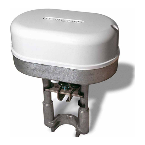
SH222 - SH242 actuators
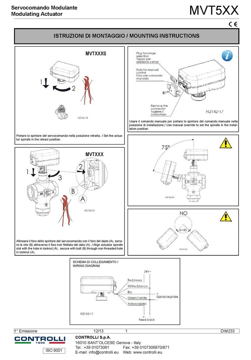
Make connections according to diagram and according to the
rules in force.
Supply actuators to terminals L and L’ by transformer of suit-
able power.
To select supply transformers it is necessary to add up the
consumption of actuators used.
If electrical connections are realized as per diagram: terminals
B R V of controller to terminals B R V of actuator, actuator turns
clockwise on temperature rise and counter clockwise on tem-
perature drop.
To reverse rotation way it is necessary to exchange terminal B
with terminal V on actuator.
L2 and M terminals are jumpered and have 0 value; conse-
quently, powering by only a transformer both the actuator and
the controller it is necessary respect the phases (for Line 500
controllers: 1 of controller with L1 of actuator, the same for 2-
L2). The controller signal must be conducted to Y terminal of
the actuator.
For M -V+ terminals the 15 Vdc (max 100 mA) voltage is avail-
able.
Auto-transformers must not be used.
To select supply transformers it is necessary to add up the
consumption of actuators used, be careful that the transformer
must supply three actuators max.
In case of more than one actuator is used, be sure that the
same phase is connected to all L1 terminals and the re-
maining phase to all L2 terminals of actuators.
The actuator is supplied with direct action (clockwise rotation
for increasing signal). For reversing the direction of the rota-
tion it is necessary to reverse the controller action by connect-
ing to 5terminal instead of to 5 terminal.
REMOTE INDICATOR: remote control signal
The remote indicator CM511 is used for remote manual con-
trol of an actuator. For connections see the schema shown on
this page.
If more actuators are controlled by only a controller, it is advis-
able to reverse the clockwise rotation, by moving the SW2
jumper from A to C.
The actuators are equipped for control signal 0 ÷ 10 Vdc.
To select different ranges, it is necessary to move the jumper
into position chosen. For 4 ÷20 mA range, it is necessary to
insert 2 jumpers, using also the one arranged in open posi-
tion.
Size cable
1,0
1,5
2,5
Max wire lenght
220
L1 Phase power supply
L2 Neutral 24 V∼ +10/-15%
MCommon
V+ +15 V output
YControl signal
S1 Analogue common
S2 0...10V- or 0...200 uA
S3 10...0V- or 200...0 uA
ATTENTION: the connection cable must be separated from the sen-
sor-controller ones and they must not be placed into elios pipes having
voltage line. Supply actuators to terminals L and L’ at 24 V ~ ± 10%by
transformer of suitable power.
*In case of W and TX controller connect only to 5 terminal and
respect the power supply 1 and 2 or L1 and L2 phases.
N3100
N3092
N3134
Make connections according to the wiring diagrams shown on
data sheets of Line 500 controllers and aux. modules.
For connections use section wires as follows:
*Internally connected
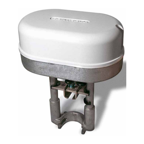
SH522 actuators
