Beckman Couler UniCel DxC 600 Installation guide

© Copyright 2005 Beckman Coulter, Inc.
BECKMAN COULTER, INC. • 4300 N. Harbor Blvd., Fullerton, CA 92835 U.S.A.
A24183-AA
May 2005
In-Lab Training Manual
This manual is intended for use with
UniCel®DxC 600 and DxC 800
Synchron®Clinical Systems
®


UniCel DxC 600/800 In-Lab Training Manual A24183 Table of Contents
May 2005 Page 1 of 4
Table of Contents
CHAPTER 1 System Components ........................................................................................ 1-1
Instrument Overview ....................................................................................... 1-1
General Introductions ................................................................................... 1-1
System Components ..................................................................................... 1-1
Sample Handling Components ..................................................................... 1-2
Sample Racks ............................................................................................. 1-3
Autoloader and Off Load Trays ................................................................. 1-3
RUN, Priority Load and STOP Buttons ..................................................... 1-3
Pushers Gate and Shuttle ........................................................................... 1-4
Bar Code Reader ........................................................................................ 1-4
Cap Piercing Assembly (Systems with CTS) ............................................ 1-4
Sample Carousel ........................................................................................ 1-4
Sample Probes ............................................................................................ 1-4
Obstruction Detection Assembly ............................................................... 1-5
Modular Chemistry (MC) System ................................................................ 1-6
Electrolyte Injection Cup (EIC) ................................................................. 1-8
Flow Cell Assembly ................................................................................... 1-9
Reaction Cup Module(s) ............................................................................ 1-9
Cartridge Chemistry (CC) System .............................................................. 1-10
Reagent Cartridges ................................................................................... 1-11
Reagent Carousel ..................................................................................... 1-11
Reagent Probes/Mixers ............................................................................ 1-11
Reaction Carousel .................................................................................... 1-12
Photometer and LPIA Assemblies ........................................................... 1-12
Cuvette Wash Station ............................................................................... 1-13
Hydropneumatics System ........................................................................... 1-14
System Console ........................................................................................... 1-15
CHAPTER 2 Software Overview .......................................................................................... 2-1
General Introductions ................................................................................... 2-1
Main Operator Screen ................................................................................... 2-2
CTS Indicator ............................................................................................. 2-2
Host Indicator ............................................................................................ 2-2
System Status Indicator ............................................................................. 2-2
Function Select Icons ................................................................................. 2-2
Sample Status Icons ................................................................................... 2-3
Rack Status ................................................................................................ 2-3
CHAPTER 3 Procedures and Processes ................................................................................ 3-1
Daily Start Up Procedures ............................................................................ 3-1
Check Status and Clear Sample Racks ......................................................... 3-2
When to Do ................................................................................................ 3-2
Result ......................................................................................................... 3-2

Table of Contents UniCel DxC 600/800 In-Lab Training Manual A24183
Page 2 of 4 May 2005
Quick Tips .................................................................................................. 3-2
Additional References ................................................................................ 3-2
Procedure ................................................................................................... 3-3
Check Status and Reagent Load of MC Reagents ........................................ 3-4
When to Do ................................................................................................ 3-4
Result ......................................................................................................... 3-4
Quick Tips .................................................................................................. 3-4
Additional References ................................................................................ 3-4
Procedure ................................................................................................... 3-4
Check Status and Reagent Load of CC Reagents ......................................... 3-6
When to Do ................................................................................................ 3-6
Result ......................................................................................................... 3-6
Quick Tips .................................................................................................. 3-6
Additional References ................................................................................ 3-6
Procedure ................................................................................................... 3-7
Calibration .................................................................................................... 3-9
When to Do ................................................................................................ 3-9
Result ......................................................................................................... 3-9
Quick Tips .................................................................................................. 3-9
Additional References ................................................................................ 3-9
Procedure ................................................................................................... 3-9
Sample Preparation and Sample Containers ............................................... 3-11
When to Do .............................................................................................. 3-11
Result ....................................................................................................... 3-11
Quick Tips ................................................................................................ 3-11
Additional References .............................................................................. 3-11
Procedure ................................................................................................. 3-12
Program/Process QC ................................................................................... 3-15
When to Do .............................................................................................. 3-15
Result ....................................................................................................... 3-15
Quick Tips ................................................................................................ 3-15
Additional References .............................................................................. 3-15
Procedure ................................................................................................. 3-16
Processing Bar Coded Patient Samples ...................................................... 3-17
When to Do .............................................................................................. 3-17
Result ....................................................................................................... 3-17
Quick Tips ................................................................................................ 3-17
Additional References .............................................................................. 3-17
Procedure ................................................................................................. 3-17
Processing Unreadable Bar Code Patient Samples ..................................... 3-18
When to Do .............................................................................................. 3-18
Result ....................................................................................................... 3-18
Quick Tips ................................................................................................ 3-18
Additional References .............................................................................. 3-18
Procedure ................................................................................................. 3-18
Programming and Processing Patient Samples Manually .......................... 3-19
When to Do .............................................................................................. 3-19
Result ....................................................................................................... 3-19

UniCel DxC 600/800 In-Lab Training Manual A24183 Table of Contents
May 2005 Page 3 of 4
Quick Tips ................................................................................................ 3-19
Additional References .............................................................................. 3-19
Procedure ................................................................................................. 3-19
Power Down and Power Up ........................................................................ 3-21
When to Do .............................................................................................. 3-21
Result ....................................................................................................... 3-21
Additional References .............................................................................. 3-21
Procedure ................................................................................................. 3-21
Procedure ................................................................................................. 3-22
CHAPTER 4 Training ............................................................................................................ 4-1
In-Lab Training Checklist ............................................................................. 4-1
Purpose ....................................................................................................... 4-1
UniCel DxC Competency Exercise ................................................................. 4-5
How to Use this Exercise ........................................................................... 4-5
Reagents ..................................................................................................... 4-5
Calibration ................................................................................................. 4-6
QC .............................................................................................................. 4-6
Samples ...................................................................................................... 4-6
Review Results .......................................................................................... 4-7
UDR ........................................................................................................... 4-8
Instrument Commands ............................................................................... 4-8
Answer Key .................................................................................................. 4-9
Reagents ..................................................................................................... 4-9
Calibration ............................................................................................... 4-10
Samples .................................................................................................... 4-10
UDR ......................................................................................................... 4-10
Instrument Commands ............................................................................. 4-10

Table of Contents UniCel DxC 600/800 In-Lab Training Manual A24183
Page 4 of 4 May 2005

General Introductions
UniCel DxC 600/800 In-Lab Training Manual A24183 System Components
May 2005 Page 1-1
1
CHAPTER 1 System Components
Instrument Overview
General Introductions
The UniCel®DxC Synchron®Clinical System is a fully automated, console
computer-controlled clinical chemistry analyzer designed for the in vitro
determination of a variety of general chemistries, therapeutic drugs, and other
chemistries. Analysis can be performed on serum, plasma, urine or cerebrospinal fluid
(CSF) and pre-treated whole blood (sample type is chemistry dependent).
Figure 1.1 DxC 600/800 Analyzers
System Components
Both UniCel DxC 600 and DxC 800 can be divided into the following components:
• Sample Handling Components,
• Modular Chemistry (MC) System,
• Cartridge Chemistry (CC) System,
• Hydropneumatic System,
• System Console.
DxC 600 DxC 800
A007386P.EPS
Sample Handling Components
System Components UniCel DxC 600/800 In-Lab Training Manual A24183
Page 1-2 May 2005
Sample Handling Components
For both DxC 600 and DxC 800 systems, the Sample Handling System is used:
• To load samples onto the system,
• To provide samples for analysis, and
• To provide temporary storage of completed samples.
The Sample Handling System is composed of the following:
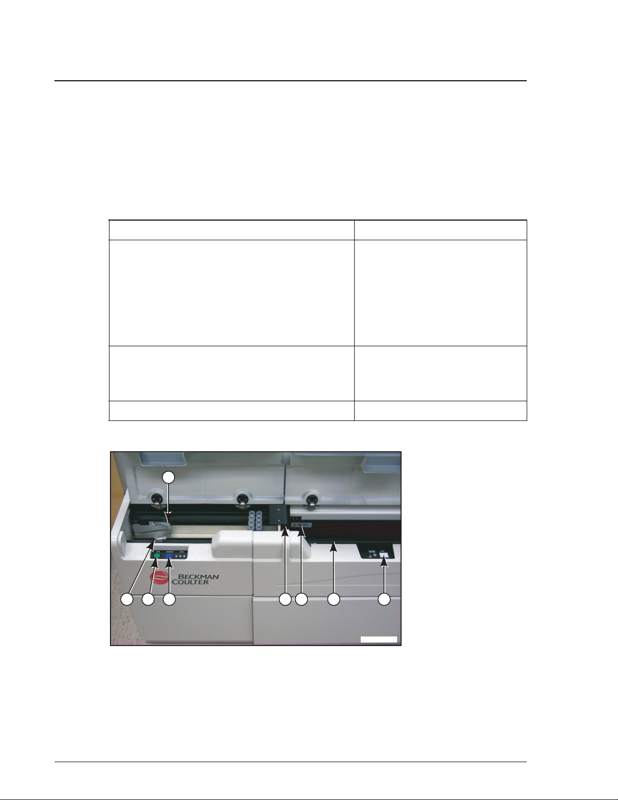
Figure 1.2 Sample Loading Area
Component Function
• Sample Racks
• Autoloader Tray
• RUN, Priority Load and STOP Buttons
• Pushers, Gate and Shuttle
• Bar Code Reader
• Cap Piercing Assembly (Optional)
For loading of sample onto the
system
• Sample Carousel
• Sample Probes
• Obstruction Detection Assembly
For sample analysis
• Off Load Tray For storage of Completed samples
1. Pushers
2. Autoloader
3. Run button
4. Priority load button
5. Sample gate
6. Shuttle
7. Offload track
8. Stop button
A015902P.EPS
2 3 4 8765
1

Sample Handling Components
Sample Racks
UniCel DxC 600/800 In-Lab Training Manual A24183 System Components
May 2005 Page 1-3
1
Sample Racks
A sample rack is a high-strength, plastic, centrifugable holder designed to house up to
4 samples. There are 4 sizes of racks with each size capable of holding one length/
width combination of primary sample tubes in addition to accepting sample cups.
Figure 1.3 Sample Rack
Autoloader and Off Load Trays
The autoloader tray holds sample racks before they are presented to the instrument.
Once the sample racks have been processed by the DxC system, the racks are placed in
the Off Load Tray.
When viewed from the front of the system, the autoloader tray is located on the left
while the Off Load Tray is located on the right. The DxC 800 autoloader tray can hold
up to 25 sample racks. The DxC 600 autoloader tray can hold up to 14 sample racks.
RUN, Priority Load and STOP Buttons
Located by the Autoloader Tray is the RUN button. When pressed, the system moves
the sample racks into the instrument’s sample carousel. The PRIORITY LOAD button
is used to interrupt the process so that a rack containing a high priority sample can be
placed ahead of the other racks.
The STOP button is located near the Off Load Tray and it is used to mechanically stop
all instrument movements.
1. Numeric Rack ID number
2. Rack Size label
3. Bar coded rack ID label

Sample Handling Components
Pushers Gate and Shuttle
System Components UniCel DxC 600/800 In-Lab Training Manual A24183
Page 1-4 May 2005
Pushers Gate and Shuttle
When the RUN button is pressed, pushers move the racks toward the gate. From there
the shuttle guides the rack from the gate onto the Sample Carousel. When sample
analysis has completed, the shuttle guides the rack back to the gate where it is then
moved towards the Off Load Tray.
Bar Code Reader
The bar code reader reads the rack’s bar code, the sample’s bar code (if present), and
the background bar code (affixed on the instrument) as the rack travels past the reader.
The rack’s bar code and the sample’s bar code are used to identify the sample and link
it to the appropriate sample programming. The background bar code is used to
determine whether a rack position is empty or occupied. If it is determined that the
position is occupied, the background bar code helps in determining if the container is a
primary tube or a cup.
Cap Piercing Assembly (Systems with CTS)
UniCel DxC Systems have the optional 1-blade Closed Tube Sampling (CTS)
Assembly. Its function is to pierce validated thick-stoppered tubes thus allowing the
sample probe to access the sample without the need for cap removal. The CTS is
compatible with the Beckton Dickinson VACUTAINER®Tubes with HEMOGARD™
closure and the Greiner VACUETTE®Tubes.
Sample Carousel
The sample carousel can hold up to 10 racks at any one time. Under normal operation,
8 of the sample carousel positions are available for routine processing and 2 positions
are reserved for priority racks.
Sample Probes
There are 2 sample probe/crane assemblies (one for the MC system and one for the CC
system) on the UniCel DxC system. Attached to each crane is a sample probe. Each
crane has its own set of motors that allow for rotational and vertical motion.
A sample probe’s primary function is to aspirate adequate volume of sample and to
dispense the sample at a designated location for analysis.
Attached to each probe is a collar wash assembly that automatically cleans the exterior
of the probe as it travels back towards the Home position. The interior of the probe is
rinsed and the waste is collected while at the Home position.

Sample Handling Components
Obstruction Detection Assembly
UniCel DxC 600/800 In-Lab Training Manual A24183 System Components
May 2005 Page 1-5
1
Obstruction Detection Assembly
Each sample probe has its own Obstruction Detection and Correction (ODC)
Assembly. The ODC assembly is used to detect the difference between a normal fluid
specimen and a clotted specimen.
Detailed information regarding the Obstruction Detection Assembly can be found in
the UniCel DxC Synchron Clinical Systems Instructions For Use manual,
CHAPTER 2, System Description.
Modular Chemistry (MC) System
Obstruction Detection Assembly
System Components UniCel DxC 600/800 In-Lab Training Manual A24183
Page 1-6 May 2005
Modular Chemistry (MC) System
The Modular Chemistry (MC) System performs rapid analysis of the more commonly
ordered, high volume analytes in parallel with the Cartridge Chemistry (CC) System.
The Modular Chemistry System is composed of the following:
Component Function
Reagent Storage Area Holds reagents required for testing by the Modular
Chemistry System.
Exceptions:
• The Alkaline Buffer Reagent (used for CO2testing) is
housed in the Flow Cell Assembly.
• The following reagents are housed in the
Hydropneumatics Compartment:
- No Foam Reagent
- Wash Concentrate
- Auto-Gloss (For Systems with Cap Piercing)
Electrolyte Injection Cup
(EIC)
The EIC mixes the sample with Electrolyte Buffer
reagent prior to the delivery (of sample) to the flow cell.
Flow Cell Assembly Rapid analysis of sodium (Na), potassium (K), chloride
(CL), carbon dioxide (CO2) and total calcium (CALC) is
performed in the flow cell module using electrodes
specific for each analyte.
Discrete Reaction Cup
Module(s)
DxC 600 systems have one-cup module for the rapid
analysis of glucose.
DxC 800 systems have 6 individual cup modules for the
rapid analysis of glucose, BUN/UREA, creatinine,
phosphorus, albumin and total protein.
Modular Chemistry (MC) System
Obstruction Detection Assembly
UniCel DxC 600/800 In-Lab Training Manual A24183 System Components
May 2005 Page 1-7
1
Figure 1.4 DxC 800 Modular Chemistry System
Figure 1.5 DxC 600 Flow Cell Assembly
1. EIC
2. BUNm (DxC 800 only)
3. PHOSm (DxC 800 only)
4. GLUCm
5. CREm (DxC 800 only)
6. TPm (DxC 800 only)
7. ALBm (DxC 800 only)
A007387P.EPS
7
5
4
32
1
6
A007388P.EPS

Modular Chemistry (MC) System
Electrolyte Injection Cup (EIC)
System Components UniCel DxC 600/800 In-Lab Training Manual A24183
Page 1-8 May 2005
Electrolyte Injection Cup (EIC)
The EIC mixes the sample with Electrolyte Buffer reagent prior to the delivery (of
sample) to the flow cell.
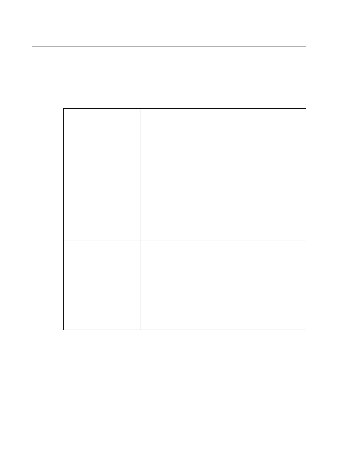
Figure 1.6 EIC
1. Waste Outlet
2. Flow Cell Outlet
3. Buffer Inlet
4. Reference Inlet
5. DI H20 Inlet

Modular Chemistry (MC) System
Flow Cell Assembly
UniCel DxC 600/800 In-Lab Training Manual A24183 System Components
May 2005 Page 1-9
1
Flow Cell Assembly
The flow cell assembly houses the 7 electrodes that perform the analysis of sodium,
potassium, chloride, carbon dioxide and calcium.
Figure 1.7 Flow Cell
Reaction Cup Module(s)
The DxC 600 system has one reaction cup module (GLUCm); whereas the DxC 800
system has 6 reaction cup modules (GLUCm, BUNm, CREm, PHOSm, ALBm and
TPm).
Each reaction cup module has similarities in their design. Each reaction cup module
has the following:
• Reagent pump assembly
- Delivers precise amount of reagent to the respective cups
• Reaction cup
- Serves as the reaction vessel for each module
• Stir bar and mixer motor assembly
- Effectively mixes the contents of the reaction cup
• A detection system
- (Chemistry dependent) serves to detect light transmitted or electrical changes
1. Inlet port
2. CI electrode
3. K electrode
4. CO2reference electrode
5. CO2electrode
6. Exit port for waste (large tube)
7. Exit port for internal reference
8. Na reference electrode
9. Na electrode
10. Ca electrode

Cartridge Chemistry (CC) System
Reaction Cup Module(s)
System Components UniCel DxC 600/800 In-Lab Training Manual A24183
Page 1-10 May 2005
Cartridge Chemistry (CC) System
The Cartridge Chemistry (CC) System gets its name based upon the fact that the
chemistries are packages in reagent containers called cartridges. These cartridge
chemistries can be accessed by the system in a random-access manner.
The Cartridge Chemistry System is composed of the following:
Component Function
Reagent Cartridges Houses the individual liquid reagent components
necessary to perform a chemistry test.
Reagent Carousel Provides on-board storage for up to 59 individual
reagent cartridges.
Reagent Bar Code Readers Scans the reagent cartridge’s bar code label during the
loading and unloading of a reagent cartridge.
Reagent Probes/Mixer
Assembly
The reagent probe aspirates reagent(s) from a reagent
cartridge and dispenses it into a reaction cuvette. If
more than one reagent is dispensed, the reagent mixer
mixes the cuvette’s contents.
Reaction Carousel Serves as the reaction vessel for the CC system.
Photometer Assembly Obtains absorbance readings from each cuvette during
the analysis cycle.
Large Particle Immuno
Assay (LPIA) Assembly
(Optional)
Obtains reaction readings for large particle
immunoassays.
Note: Also known as Near Infrared Particle Immuno
Assay (NIPIA).
Cuvette Wash Station Washes cuvettes at the completion of analysis in
preparation for the next chemistry.
Cartridge Chemistry (CC) System
Reagent Cartridges
UniCel DxC 600/800 In-Lab Training Manual A24183 System Components
May 2005 Page 1-11
1
Reagent Cartridges
Reagent cartridges are single-use, recyclable plastic containers that house individual
reagents necessary to perform a chemistry test.
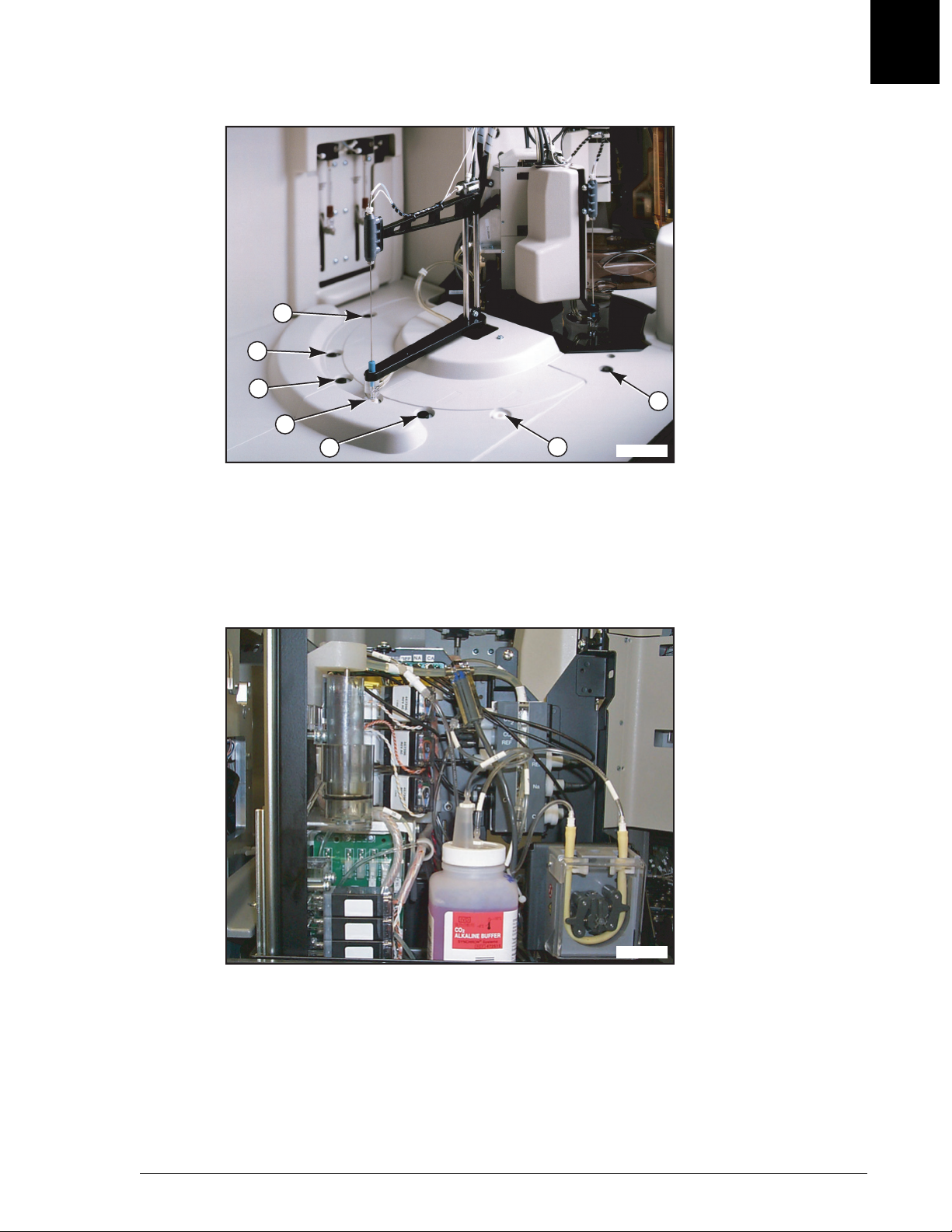
Figure 1.8 CC Reagent Cartridge
Reagent Carousel
The reagent carousel is refrigerated and fan-cooled to maintain a temperature of +5°C
(±3°C). Cartridges are loaded into the carousel by lifting the access door located in
front of the carousel. Depending on which position was selected for reagent load, the
appropriate bar code reader will scan the cartridge’s bar code label. The bottom
portion holds position 1 through 30; the top portion of the reagent carousel holds
position 31 through 59.
Reagent Probes/Mixers
Similar to the Sample Probe, the reagent probes’ primary function is to aspirate and
dispense reagents. Like the sample probe, a collar wash assembly is attached to the
reagent probe for automatic cleaning of the probe as it is traveling. Both reagent
probes on the UniCel DxC work in tandem to provide maximum throughput and
efficient reagent delivery.
1. A compartment
2. B compartment
3. C compartment

Cartridge Chemistry (CC) System
Reaction Carousel
System Components UniCel DxC 600/800 In-Lab Training Manual A24183
Page 1-12 May 2005
Reaction Carousel
The reaction carousel assembly houses 125 glass cuvettes. The cuvettes are
non-disposable and have an indefinite life span on the instrument. The carousel is
thermally controlled to 37°C ±0.1°C.
The carousel is capable of rotation movement. During a rotational spin, the cuvettes
pass in front of the Photometer and LPIA Assembly where readings are taken to
monitor reactions.
Figure 1.9 Reagent Carousel Area
Photometer and LPIA Assemblies
The Photometer assembly consists of a xenon pulse lamp, a discrete 10-position
detector array, a monochromator housing unit and associated electronic circuitry. As
each cuvette passes through the photometer assembly during a rotational cycle, the
xenon lamp flashes and the resulting light beam travels through the opposing sides of
the cuvette. The electrical signal produced when the light strikes the photodetectors is
then converted to a digital value.
The LPIA assembly is an optional feature. It operates independently from the
Photometer assembly. Additional information about the LPIA assembly may be found
in the UniCel DxC Synchron Clinical Systems Instructions For Use manual,
CHAPTER 2, System Description, Cuvette Reaction System.
1. Location of photometer (under system cover)
2. Reaction carousel
3. Location of LPIA module (under system cover)

Cartridge Chemistry (CC) System
Cuvette Wash Station
UniCel DxC 600/800 In-Lab Training Manual A24183 System Components
May 2005 Page 1-13
1
Cuvette Wash Station
The Cuvette Wash Station System consists of 4 probes, an elevator assembly and
various tubings. The first 2 probes vacuum the waste contents from the cuvettes and
dispense wash solution. The third probe vacuums the wash solution and dispenses DI
Water. The last probe removes DI water from the cuvette, leaving it dry and ready for
the next chemistry.
Figure 1.10 Cuvette Wash Station
1. Probe #1
2. Probe #2
3. Probe #3
4. Probe #4
5. Wash station
Hydropneumatics System
Cuvette Wash Station
System Components UniCel DxC 600/800 In-Lab Training Manual A24183
Page 1-14 May 2005
Hydropneumatics System
Mounted on a slide-out drawer is the Hydropneumatics System. Its primary function
is to provide vacuum, compressed air, diluted wash solution and deionized water to the
instrument.
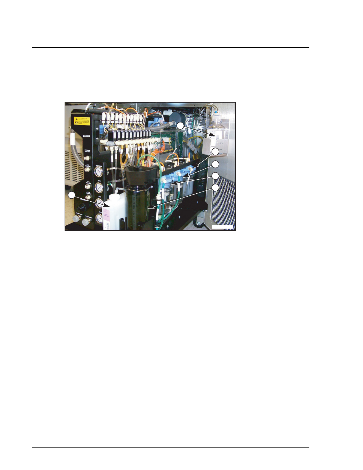
Figure 1.11 DxC Hydropneumatics
1. Wash concentrate solution
2. No foam reagent
3. DI water reservoir
4. Dilute wash solution reservoir
5. Wash concentrate reservoir
6. Auto-Gloss
A016497P.EPS
6
1
2
3
4
5
This manual suits for next models
1
Table of contents
Other Beckman Couler Laboratory Equipment manuals


Popular Laboratory Equipment manuals by other brands

Ovation
Ovation F1 Quick reference guide

PI Micos
PI Micos dt-80 user manual

Endress+Hauser
Endress+Hauser Liquistation CSF39 operating instructions

Thermo Scientific
Thermo Scientific Applied Biosystems QuantStudio 6 Pro user guide
BeaconMedaes
BeaconMedaes VerusLab 4107 9021 88 Installation, operation and maintenance instructions

Kurabo
Kurabo QuickGene-810 Operation manual


