Beckman Coulter CSD2 User manual

Instructions for Use
StatSpin CritSpin Digital Reader Model Number S120
For In Vitro Diagnostic Use
This manual is intended for
CSD2 Digital Reader -with tube adapter for 75mm tubes, and with a universal power
supply.
Printed in U.S.A.
55-003823-001CC
September 2018
Beckman Coulter, Inc.
250 S. Kraemer Blvd.
Brea, CA 92821 U.S.A.

Instructions for Use
StatSpin CritSpin Digital Reader Model Number S120
PN 55-003823-001CC (September 2018)
© 2018 Beckman Coulter, Inc.
All Rights Reserved.
Trademarks
Beckman Coulter, the stylized logo, and the Beckman Coulter product and service marks mentioned
herein are trademarks or registered trademarks of Beckman Coulter, Inc. in the United States and other
countries.
All other trademarks are the property of their respective owners.
Find us on the World Wide Web at:
www.beckmancoulter.com
Rx Only
Original Instructions

Revision History
55-003823-001 CC, 09/2018
• Moved: Symbol/Regulatory Mark and a link to the website in the California
Proposition 65 statement
55-003823-001 CB, 03/2018
• Converted the CritSpin Digital Reader Operations Manual to a Beckman Coulter
Instructions for Use (IFU) Manual, and made general clarification to the IFU
• Added: Revision History, Safety Notice, Symbols and Definitions table, Alerts for
Warning, Caution, Important, Note, and Tip explanations, and Warning and Cautions
• Updated: Logo, Manufacturer address, and Limited Warranty statement
• Deleted: EC Rep
55-003823-001CC iii

Revision History
iv 55-003823-001CC

Safety Notice
Read all product manuals and consult with Beckman Coulter-trained personnel before you
operate the system. Do not perform any procedure before you carefully read all
instructions. Always follow the product labels and the manufacturer’s recommendations. If
you have any questions:
• Visit http://www.beckmancoulter.com.
• US customers: Contact Beckman Coulter Customer Support at 1-800-854-3633.
• International customers: Contact your local distributor.
Alerts for Warning, Caution, Important, Note, and Tip
Warning
Warning indicates a potentially hazardous situation which, if not avoided, could
cause death or serious injury. Warning can indicate the possibility of erroneous data
that could cause an incorrect diagnosis.
Caution
Caution indicates a potentially hazardous situation which, if not avoided, can cause
minor or moderate injury. Caution can also alert against unsafe practices, or indicate
the possibility of erroneous data that could cause an incorrect diagnosis.
Important
Important indicates important information to follow.
Note
Note indicates notable information to follow.
Tip
Tip indicates information to consider.
Warning and Cautions
Pay close attention to the instructions that accompany the notes and symbols and the
standard laboratory procedures outlined by your facility and local regulatory agencies.
55-003823-001CC v

Warning
Perform system operations with caution.
Wear Personal Protective Equipment (PPE) such as gloves, eye shields, and lab coats.
Wash hands thoroughly after contact with sample media and all maintenance
activities.
Observe all laboratory policies and procedures related to the handling of
biohazardous materials.
Refer to the applicable sources (such as Material Safety Data Sheets) for specific
hazard information.
Warning
If the equipment is used in a manner not specified by Beckman Coulter, the
protection provided by the equipment may be impaired.
Warning
Outside of North America: do not use the power cord supplied. Use power cord for at
least 1.0 Amp with an IEC320/CEE22 female connector and male connector suitable
for the power outlet to be used.
Warning
Electromagnetic Wave and Noise
The system generates, uses, and can radiate radio frequency energy. If the system is
not installed and operated correctly, this energy can cause interference with other
equipment. In addition, other equipment can radiate radio frequency energy to
which the system is sensitive. If you suspect interference between the system and
other equipment, Beckman Coulter recommends the following actions to correct the
interference:
•This equipment complies with the emission and immunity requirements described in this
part of the EN/IEC 61326 -1
•As to emission, this system has been designed and tested to CISPR 11 Class A, so in a
domestic environment, it may cause radio interference, in which case, you may need to
take measure to mitigate the interference.
•It is recommended to evaluate the electromagnetic environment prior to operations of
the system.
•Do not use this system in close proximity to sources of strong electromagnetic radiation
(for example, unshielded intentional RF sources). As they can interfere with the proper
operation.
Safety Notice
Warning and Cautions
vi 55-003823-001CC
•Do not use mobile or cordless telephones and transceivers in the same room as the
system.
•Do not use medical equipment that can be susceptible to malfunctions caused by Electric
Magnetic Field (EMF) near the system.
Please use the instrument as intended. Improper use may cause damage to the instrument,
inaccurate results, or potentially nullify warranties.
Symbols and Definitions
CritSpin Symbols GlossaryTable 1
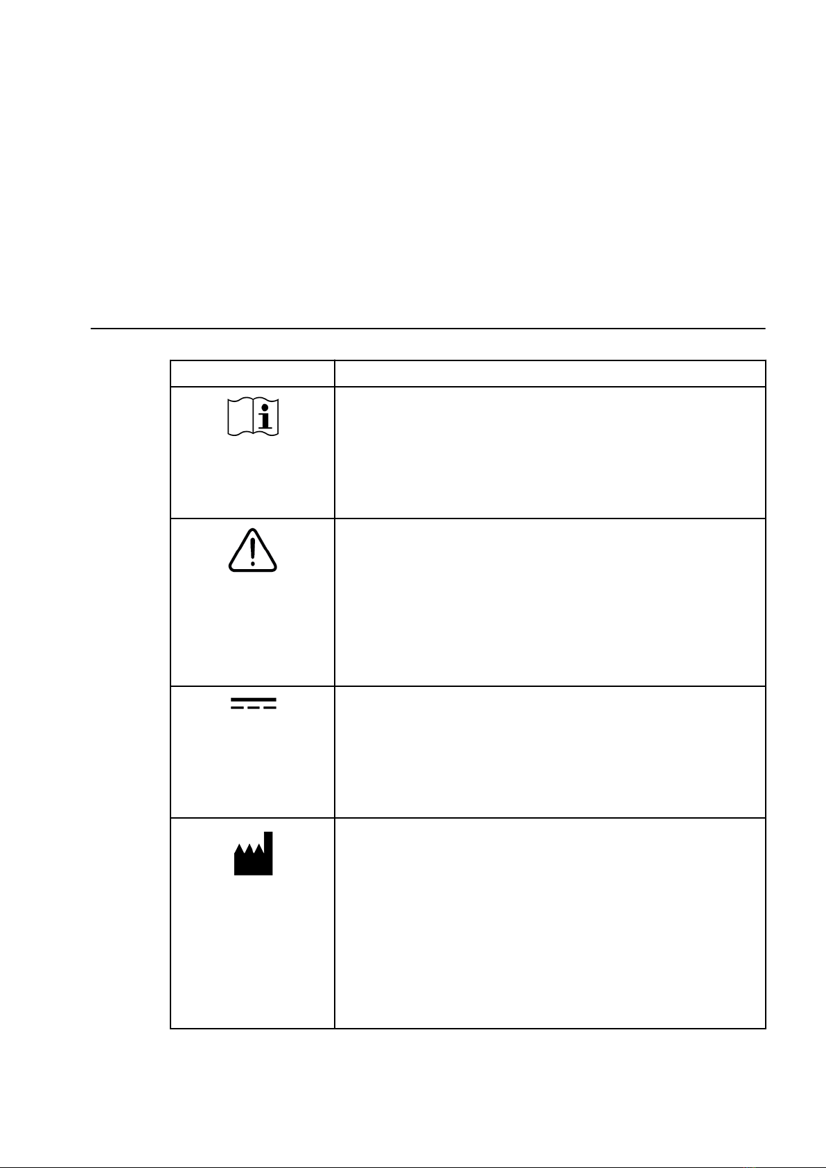
Symbol Description
Consult instructions for use
Indicates the need for the user to consult the instructions for use.
ISO 15223-1. Medical devices - Symbols to be used with medical device
labels, labelling and information to be supplied - Part 1: General
Requirements. #5.4.3
Caution
Indicates the need for the user to consult the instructions for use for
important cautionary information such as warnings and precautions that
cannot, for a variety of reasons, be presented on the medical device itself.
ISO 15223-1. Medical devices - Symbols to be used with medical device
labels, labelling and information to be supplied - Part 1: General
Requirements. #5.4.4
Direct current
To indicate on the rating plate that the equipment is suitable for direct
current only; to identify relevant terminals.
IEC 60417: Graphical symbols for use on equipment - Overview and
application, #5031
Manufacturer
Indicates the medical device manufacturer as defined in EU Directives
90/385/ EEC, 93/42/EEC and 98/79/EC.
ISO 15223-1. Medical devices - Symbols to be used with medical device
labels, labelling and information to be supplied - Part 1: General
Requirements. #5.1.1
Supplemental Product-Specific Manufacturer Information
This symbol identifies who the legal manufacturer of the product is.
Safety Notice
Symbols and Definitions
55-003823-001CC vii
CritSpin Symbols Glossary (Continued)
Table 1
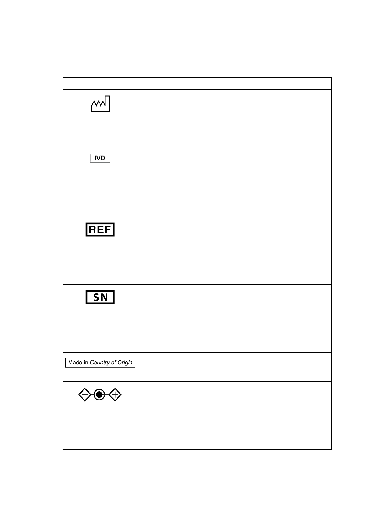
Symbol Description
Date of Manufacture
To indicate the date when the medical device was manufactured.
ISO 15223-1. Medical devices - Symbols to be used with medical device
labels, labelling and information to be supplied - Part 1: General
Requirements. #5.1.3
In vitro diagnostic medical device
Indicates a medical device that is intended to be used as an in vitro
diagnostic medical device.
ISO 15223-1: Medical devices. Symbols to be used with medical device
labels, labelling and information to be supplied. General requirements,
clause 5.5.1
Catalogue Number
Indicates the manufacturer's catalogue number so that the medical device
can be identified.
ISO 15223-1. Medical devices - Symbols to be used with medical device
labels, labelling and information to be supplied - Part 1: General
Requirements. #5.1.4
Serial number
Indicates the manufacturer's serial number so that a specific medical
device can be identified.
ISO 15223-1. Medical devices - Symbols to be used with medical device
labels, labelling and information to be supplied - Part 1: General
Requirements. #5.1.7
Country of Origin Symbol
This symbol indicates the country that the product was manufactured.
Polarity of d.c. power connector
To identify the positive and negative connections (the polarity) of a d.c.
power supply, or the positive and negative connections on a piece of
equipment to which a d.c. power supply may be connected.
IEC 60417: Graphical symbols for use on equipment - Overview and
application, #5926
Safety Notice
Symbols and Definitions
viii 55-003823-001CC

CritSpin Symbols Glossary (Continued)
Table 1
Symbol Description
Warning; Biological hazard
To warn of a biological hazard.
IEC 60878. Graphical Symbols for electrical equipment in medical practices.
#7010-W009
Supplemental Product-Specific Manufacturer Information
This label indicates a caution to operate only with all covers in position to
decrease risk of personal injury or biohazard.
This label indicates the use of biohazardous materials in the area. Use
caution when working with possible infectious samples.
Wear Personal Protective Equipment (PPE) such as gloves, eye shields, and
lab coats. Handle and dispose of biohazardous materials according to your
laboratory procedures.
California Proposition 65
This product can expose you to chemicals known to the State of California
to cause Cancer and Reproductive Harm. For more information go to
https://www.P65Warnings.ca.gov.
Safety Notice
Symbols and Definitions
55-003823-001CC ix

Safety Notice
Symbols and Definitions
x55-003823-001CC

Contents
Revision History , iii
Safety Notice, v
CHAPTER 1: System Overview, 1-1
Intended Use, 1-1
Description, 1-1
CHAPTER 2: Operating Instructions, 2-1
Operation, 2-1
Read Spun Hematocrit Tubes inside Rotor, 2-1
Use 75 mm Adapter, 2-3
Readout Setting, 2-3
Cleaning, 2-4
Troubleshooting and Maintenance, 2-4
APPENDIX A: Specifications, A-1
Specifications , A-1
Accessories List, A-1
APPENDIX B: References, B-1
References, B-1
55-003823-001CC xi

Contents
xii 55-003823-001CC

CHAPTER 1
System Overview
Intended Use
The StatSpin CritSpin Digital Reader assists the operator in measuring spun hematocrits
from the StatSpin Centrifuges. A tube adapter is also provided to measure spun hematocrits
in 75 mm tubes from other hematocrit centrifuges.
For in vitro diagnostic use.
Description
The CritSpin Digital Reader operates from the switching power supply (PN
X01-003553-001) provided with the digital reader. Plug the power supply into the digital
reader (Digital Reader (PN CSD2).)
Important
Use only the AC Power Adapter supplied with the digital reader. Use of another power
supply will damage the Reader and void the warranty.
Figure 1.1
Reader Configuration Product No.: CSD2
55-003823-001CC 1-1

System Overview
Description
1-2 55-003823-001CC
CHAPTER 2
Operating Instructions
Operation
To use this digital reader, hematocrit tubes are filled with blood, sealed and centrifuged in
the RH12 hematocrit rotor. The procedure and step-by-step drawings for filling hematocrit
tubes can be found in your centrifuge Instructions for Use manual. Normal values are
located in your Instructions for Use manual, read the manual before performing a
hematocrit. Follow laboratory procedures when performing any procedure on body fluids.
When tubes are centrifuged, the hematocrit rotor is removed from the centrifuge and
placed into the digital reader.
Read Spun Hematocrit Tubes inside Rotor
The digital reader has a tilt bar on the underside. Use the tilt bar to provide a tilted position
from which to read tubes. You can use either position for reading.
1Install the rotor in the digital reader:
a. Move the pointer all the way to the right.
Tip
To move the pointer, gently press it down to allow a smooth gliding motion.
b. Place the rotor in the center of the digital reader.
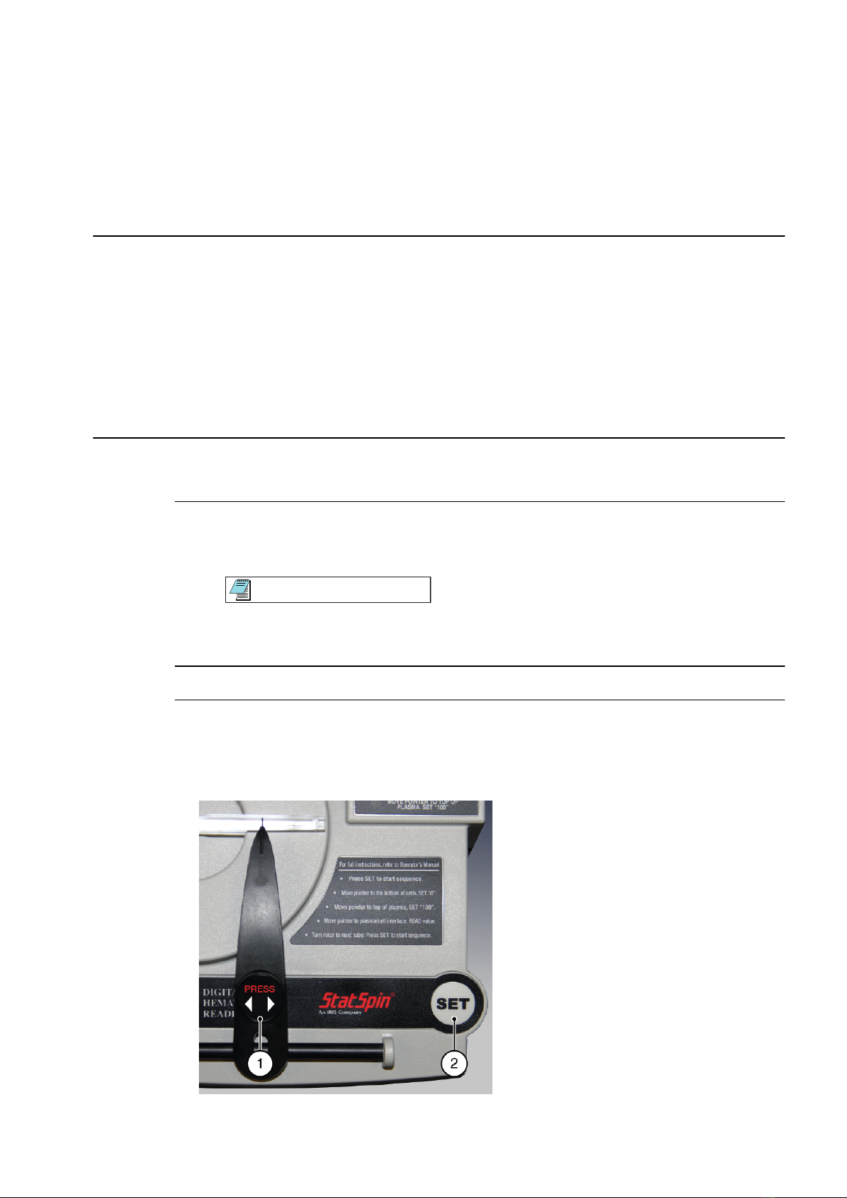
2Turn the rotor so that the first tube to be read is at the 3-o’clock position.
3To initiate the first reading, press Set.
The LED next to the label Move pointer to bottom of cells. Set "0" flashes.
Figure 2.1 Press and Set Buttons
55-003823-001CC 2-1
1. Press button 2. Set button
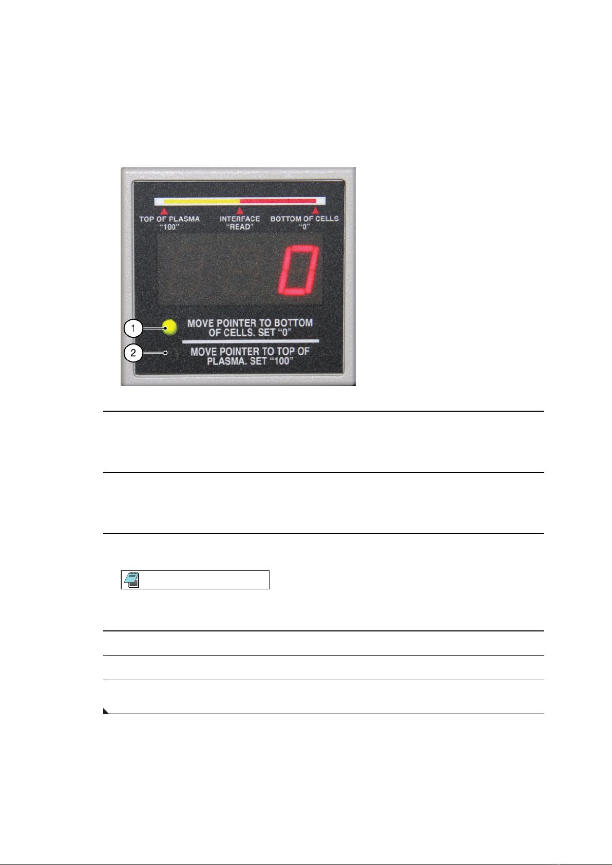
Figure 2.2 LEDs that Flash
1. LED that flashes for step 3. 2. LED that flashes for step 4.
4Move the pointer to the bottom of the red blood cells (top of the clay). Then press Set.
The system displays 0 in the digital display.
The LED next to the label Move pointer to top of plasma. Set "100" flashes.
5Move the pointer to the top of the plasma (plasma and air interface). Then press Set.
The system displays 100 in the digital display.
The digital display becomes active, and numbers change as you move the pointer.
6Move the pointer slowly to the plasma and red cell interface, and then press Press.
Note
To avoid false readings, do not press the membrane on either side of the gliding
pointer arm.
7Read the digital display, and record the number.
8Turn the rotor for the next tube to be read, and press Set to initiate the next reading.
9Continue until all tubes are read and recorded.
Operating Instructions
Read Spun Hematocrit Tubes inside Rotor
2-2 55-003823-001CC

Use 75 mm Adapter
1Move the pointer completely to the right. Place the tube adapter in the slot in the center
of the digital reader.
2Place the spun 75 mm hematocrit tube in tube adapter (clay on the right). Slide the
hematocrit tube completely to the right. Follow steps 1 to 5 in the Read Spun
Hematocrit Tubes inside Rotor to read the tube. Record the result.
Readout Setting
The digital display can be set to read either percent or decimal figures. When the digital
reader is shipped, it is set in the percent mode. The mode can be changed from a percent to
a decimal figure.
1Remove the base plate on the underside of the digital reader by removing four Phillips
screws. Set the base plate and screws aside.
2Move the jumper (small black piece) from pins 1 + 2 to pins 2 + 3.
Figure 2.3
1. Detail A
2. Jumper
3. Percent Mode
4. Pin 3
5. Negative
6. Bulb
7. Positive
8. Fiber Optic Bundle
Operating Instructions
Use 75 mm Adapter 2
55-003823-001CC 2-3

Cleaning
The instruction overlay on the digital reader has a protective coating. To clean the
instrument, dampen an absorbent tissue with warm water and a mild detergent and wipe
all surfaces.
Troubleshooting and Maintenance
The error indicator "flashing zero" indicates an error in the reading sequence. Repeat the
reading. Select Set to reset and begin the reading process.
The light is the only user-serviceable part of the digital reader. To replace the light, remove
the bottom plate by releasing the four screws on the underside. For more information, refer
to Readout Setting figure. Gently dislodge the bulb by pulling out the bulb. Remove bulb
and snap in new bulb. Replace the component to the original position.
The StatSpin CritSpin Digital Reader has no other user-serviceable parts. If a problem
occurs, the operator must contact Beckman Coulter Customer support 1-800-854-3633.
Disassembly of the unit voids the warranty.
Operating Instructions
Cleaning
2-4 55-003823-001CC

APPENDIX A
Specifications
Specifications
Product No. CSD2 (supplied with the digital reader)
Model No. S120
Electrical 24 Volts DC, 1.7 amps.
Power supplied by switching power supply for 100-240 VAC, 50/60 Hz.
Dimensions Height: 2 3/8” 6.0 cm
Width: 6 7/8" 17.5 cm
Length: 6 3/8” 16.2 cm
Weight: 1.25 lbs. 0.6 kg
Environmental Indoor use
Altitude up to 2000m
Operating temperature: 15°C to 32°C
Maximum relative humidity 80% for temperatures up to 31°C decreasing linearly
to 50% relative humidity at 40°C.
Main supply voltage fluctuations not to exceed +/- 10% of the nominal voltage.
Transient overvoltages according to installation category II
Pollution degree 2
Accessories List
CritSpin Digital Reader AccessoriesTable A.2
PN Description
X01-003553-001 Power Supply
X01-003877-001 Light Bulb for Digital Reader
X00-002227-001 RH12-1 12-position Hematocrit Rotor
Plastic and glass tubes are available from your local dealer, or Contact Beckman Coulter
Customer Support 1-800-854-3633.
55-003823-001CC A-1

Specifications
Accessories List
A-2 55-003823-001CC
This manual suits for next models
1
Table of contents
Other Beckman Coulter Medical Equipment manuals

Beckman Coulter
Beckman Coulter IM3632 User manual

Beckman Coulter
Beckman Coulter Coulter LH 700 Series Service manual

Beckman Coulter
Beckman Coulter P/ACE MDQ User manual

Beckman Coulter
Beckman Coulter VersaLyse Lysing Solution Ready-for-use User manual

Beckman Coulter
Beckman Coulter DxC 600i Installation guide

Beckman Coulter
Beckman Coulter UniCel DxC 660i Installation guide

Beckman Coulter
Beckman Coulter UniCel DxC 600 User manual

Beckman Coulter
Beckman Coulter Cytomics FC 500 User manual


