Beko FLM SF53 User manual

METPOINT®FLM SF53
FLMSF53LL220 | FLMSF53DL220 | FLMSF53LL400 | FLMSF53DL400
Thermal ow meter
Installation and operating manual
EN - English
10-221

Installation and operating manual EN
2 METPOINT®SF53
Contents
1. Safety-related information.............................................................................................................................. 4
1.1. Pictograms and symbols.......................................................................................................................... 4
1.1.1. In this documentation........................................................................................................................................................4
1.1.2. On the device.......................................................................................................................................................................4
1.2. Signal words ........................................................................................................................................... 4
1.3. Safety instructions.................................................................................................................................. 5
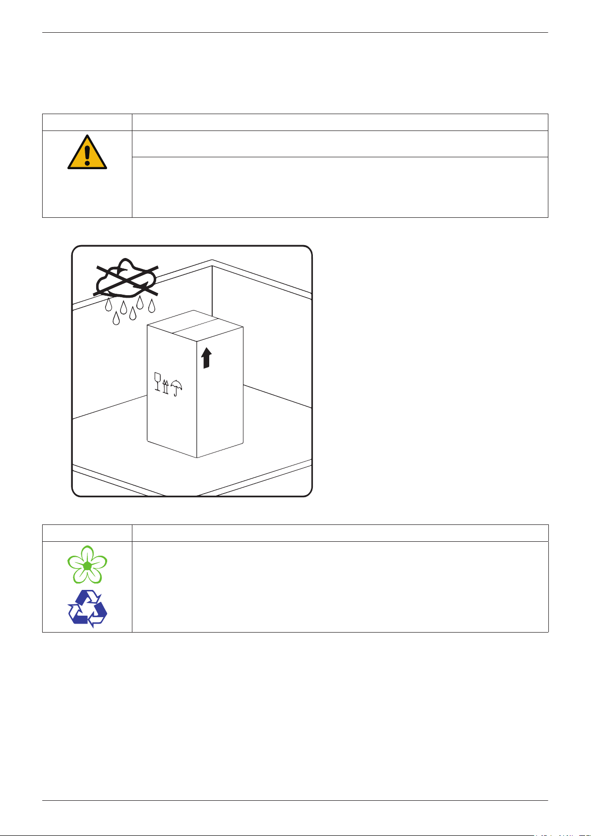
1.4. Transport and storage ............................................................................................................................. 6
1.5. Intended use........................................................................................................................................... 7
1.6. Warranty and liability for defects ............................................................................................................ 7
2. Product information ....................................................................................................................................... 8
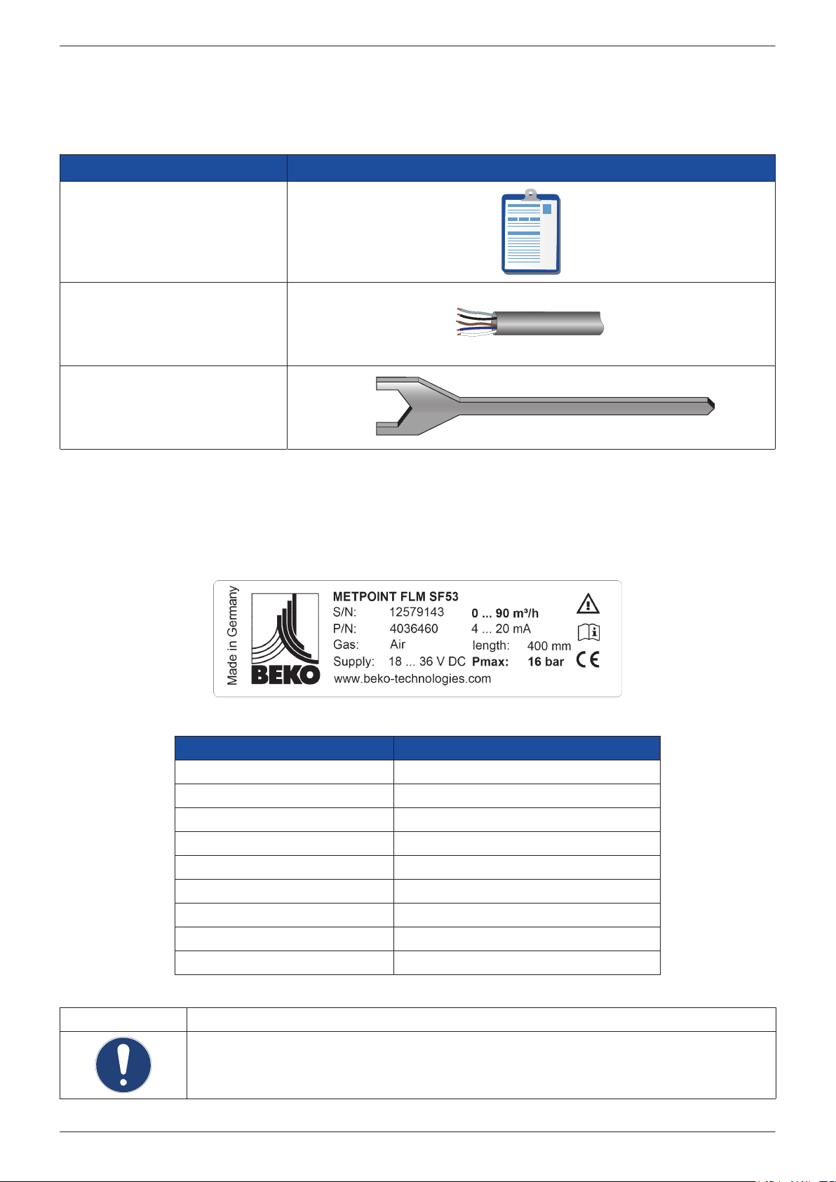
2.1. Scope of delivery .................................................................................................................................... 8
2.2. Type plate............................................................................................................................................... 8
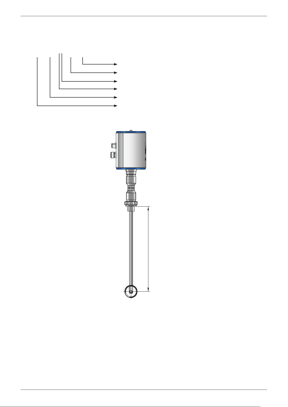
2.3. Product overview and description ........................................................................................................... 9
2.3.1. Identication based on product code.............................................................................................................................9
2.3.2. Product description ......................................................................................................................................................... 10
2.3.3. Basic operating principles.............................................................................................................................................. 10
2.4. Control and display elements ................................................................................................................ 11
2.4.1. Model with display........................................................................................................................................................... 11
2.4.2. Model with LED ................................................................................................................................................................ 11
2.4.3. Direction of ow............................................................................................................................................................... 12
2.5. Dimensions........................................................................................................................................... 13
2.6. Technical data....................................................................................................................................... 14
2.7. Measuring ranges ................................................................................................................................. 15
3. Set up ........................................................................................................................................................... 17
3.1. Warning notices.................................................................................................................................... 17
3.1.1. Requirements for pipelines............................................................................................................................................ 17
3.1.2. Requirements for the inlet/outlet pipe section ........................................................................................................ 17
3.1.3. Turning the housing......................................................................................................................................................... 18
3.2. Assembly steps ..................................................................................................................................... 19
4. Electrical installation .................................................................................................................................... 20
4.1. Pin assignment of plug-type connectors ................................................................................................ 20
4.2. Connection options............................................................................................................................... 20
4.2.1. Bidirectional RS485 bus system.................................................................................................................................... 20
4.2.2. Current output 4 ... 20 mA, 3-wire .............................................................................................................................. 21
4.2.3. MBus.................................................................................................................................................................................... 21
4.2.4. Galvanically isolated pulse output............................................................................................................................... 22
4.3. Connection of METPOINT® BDL............................................................................................................. 23
4.3.1. Bidirectional RS485 bus system.................................................................................................................................... 23
4.3.2. Current output 4 ... 20 mA, 3-wire ............................................................................................................................... 24
4.3.3. Galvanically isolated pulse output............................................................................................................................... 24
4.4. Connection to METPOINT® BDL compact............................................................................................... 25
4.4.1. Bidirectional RS485 bus system.................................................................................................................................... 25
4.4.2. Current output 4 ... 20 mA, 3-wire ............................................................................................................................... 25
4.4.3. Galvanically isolated pulse output............................................................................................................................... 26
4.5. Modbus end termination....................................................................................................................... 26

EN Installation and operating manual
METPOINT®SF53 3
5. Commissioning ............................................................................................................................................. 27
6. Conguration and operation ......................................................................................................................... 27
6.1. Indicators used in operation.................................................................................................................. 27
6.2. Setup menu .......................................................................................................................................... 28
6.3. Sensor Setup......................................................................................................................................... 28
6.3.1. Entering the pipe inner diameter ................................................................................................................................. 29
6.3.2. Entering / changing consumption counter value ..................................................................................................... 29
6.3.3. Selecting units for consumption, ow, temperature and pressure...................................................................... 30
6.3.4. Entering reference conditions....................................................................................................................................... 31
6.3.5. Setting zero point for low-ow cut-o function....................................................................................................... 32
6.4. Modbus setup ....................................................................................................................................... 33
6.4.1. Modbus settings (2001 ... 2005)................................................................................................................................... 34
6.4.2. Values register (1001 …1500)........................................................................................................................................ 34
6.5. Pulse / alarm......................................................................................................................................... 35
6.5.1. Pulse output ...................................................................................................................................................................... 35
6.6. User Setup............................................................................................................................................ 36
6.7. Advanced ............................................................................................................................................. 36
6.8. 4 ... 20 mA ............................................................................................................................................ 37
6.9. Info ...................................................................................................................................................... 38
6.10. MBus .................................................................................................................................................. 38
6.10.1. Factory communication settings................................................................................................................................ 38
6.10.2. Transmitted values......................................................................................................................................................... 38
7. Spare parts and accessories........................................................................................................................... 39
8. Maintenance and servicing............................................................................................................................ 39
9. Sensor head cleaning .................................................................................................................................... 39
10. Recalibration .............................................................................................................................................. 39
11. LED display................................................................................................................................................. 39
12. Declaration of Conformity .......................................................................................................................... 41

Installation and operating manual EN
4 METPOINT®SF53
1. Safety-related information
1.1. Pictograms and symbols
1.1.1. In this documentation
General instructions
Note the installation and operation manual
General hazard symbol (danger, warning, caution)
General hazard symbol (danger, warning, caution) for mains voltage
and mains voltage energised plant and system parts
The packaging material is recyclable. Dispose of it according to the applicable national laws and
regulations.
1.1.2. On the device
General instructions
General hazard symbol (danger, warning, caution)
1.2. Signal words
DANGER Imminent hazard
Consequences of non-compliance: serious or fatal injury
WARNING Potential hazard
Consequences of non-compliance: potentially serious or fatal injury
CAUTION Imminent hazard
Consequences of non-compliance: injury and/or damage to property
NOTE Additional notes, information, tips
Consequences of non-compliance: Disadvantages during operation and maintenance.
No risk to persons.

EN Installation and operating manual
METPOINT®SF53 5
1.3. Safety instructions
DANGER Escaping compressed gas
Risk of serious or even fatal injury from contact with escaping compressed gas or from unsecured plant
components.
• Depressurise the system before carrying out any assembly, installation or maintenance work. This
work must be performed by authorised skilled technical personnel1.
• Use only pressure-resistant installation materials and suitable tools that are in proper working order.
• Before pressurising the system, check all device parts and repair them as necessary. Open valves
slowly to prevent pressure blow-outs during operation.
• Take action to prevent people or objects from being aected by condensate or escaping compressed
gas.
• Prevent vibrations, oscillations and shocks from being transferred to system parts.
DANGER Mains voltage
Risk of electric shock with serious or fatal injuries if contact is made with non-insulated components
carrying mains voltage.
• Observe all applicable regulations with respect to electrical installations (e.g. VDE 0100/IEC 60364).
• Only execute installation and maintenance works when the system has been deenergised.
• Electrical works may only be executed by authorised skilled technical personnel1.
• Read o the permissible operating voltage on the rating plate and always comply with it.
• Only utilise components for the electrical installation which have a current approval
and are labelled with a CE-Identication Marking.
• A safely accessible circuit breaker (e.g. power plug or switch) must be provided close to the device for
disconnecting all current and/or power lines for the voltage supply.
WARNING Operating outside of limits
If the specied limits are exceeded, there is a risk of the device malfunctioning, potentially resulting in
injury and/or damage to property.
• The device must only be operated for the intended purpose and within the permissible limits
specied on the type plate and in the technical data.
• Above 10 bar, use the high-pressure safety device for safe installation and removal.
• The device is not designed for use with ammable gases.
• Ensure strict observance of operating times and maintenance intervals.
• Strictly adhere to the prescribed storage and transport conditions.
• Prevent condensation on the sensor element and water droplets in the measurement air.
1Skilled technical personnel
Skilled technical personnel use their professional qualications and knowledge in the eld of measuring, control and pneumatic
technology, and their knowledge of the applicable statutory regulations, guidelines and standards to independently foresee
potential dangers and are qualied to perform the tasks described. Special operating conditions (e.g. aggressive media) require
additional knowledge.

Installation and operating manual EN
6 METPOINT®SF53
1.4. Transport and storage
Despite our best eorts, transport damage cannot be excluded. Please therefore remove all packaging material immediately after
receipt and inspect the product for any possible transport damage. If you detect such damage, immediately notify the carrier
company and BEKO TECHNOLOGIES GMBH or one of its agents.
CAUTION Damage caused during transport or storage
Incorrect transport or storage, or the use of unsuitable lifting equipment, might cause damage to the
device.
• The device must only be transported and stored by authorised and suitably trained skilled technical
personnel.
• If you detect any damage, do not start the device.
• Always comply with the permissible storage and transport temperatures (refer to technical data).
• Never expose the device to continuous, direct sunlight or heat radiation.
The device must be stored in its original packaging.
Seal the packaging and store it in a dry and frost-
free room. Ensure that the ambient conditions do
not fall below or exceed the limits
specied on the type plate.
Even when packaged, take suitable measures to
protect the device against the elements.
While in storage, secure the device so that it
cannot topple over or fall, and protect it against
vibration.
NOTE Recycling packaging material
• The packaging material is recyclable. Dispose of the packaging material according to the applicable
statutory regulations.

EN Installation and operating manual
METPOINT®SF53 7
1.5. Intended use
The METPOINT® FLM is a thermal ow meter for the measurement of volume ow, consumption and ow velocity. In its default
setup, the device is congured for the measurement of volume ow in m³/h, consumption in m³ and velocity in m/s.
• The METPOINT® FLM is primarily used in compressed air systems. On request, the sensor can be programmed by BEKO
TECHNOLOGIES GmbH for use with other gases: Nitrogen
• The device is not suitable for operation in potentially explosive or aggressive atmospheres.
• Protect the device against direct sunlight and heat radiation.
Operate the METPOINT® FLM only for the intended purpose and within the specications as stated in the technical data. Do not
operate the device with any media (uids, gas/vapour mixtures) other than those listed above. Any other use of this system, which
exceeds the intended use, is hereby deemed to be improper and can cause a hazard for the safety of people and the environment.
1.6. Warranty and liability for defects
Warranty claims are voided if the METPOINT® FLM is used for a purpose other than the intended use or operated outside the
limits specified in the technical data. Such uses include (but are not limited to) the following:
• Technically incorrect installation, incorrect commissioning, incorrect maintenance or incorrect operation
• Operation with defective components
• Non-compliance with the instructions in this manual and the safety instructions in particular
• Execution of constructive interventions or modications on the device
• Failure to observe the prescribed maintenance intervals
• Use of third-party spare parts that have not been approved by the manufacturer for repair and maintenance work

Installation and operating manual EN
8 METPOINT®SF53
2. Product information
2.1. Scope of delivery
The table below shows the scope of delivery for the METPOINT®FLM.
Designation Illustration
Calibration certicate
Connecting cable (5-wire)
Alignment tool
2.2. Type plate
The type plate is attached to the device housing. The plate lists all of the important data for the METPOINT® FLM. Please have
these details at hand when contacting the manufacturer or supplier.
Designation Description
METPOINT®FLM SF53 Model designation
S/N: 12579143 Serial number
P/N: 4036460 Product number
Gas: air Measuring medium
Supply: 18 ... 36 VDC Data for voltage supply
0 ... 90 m³/h Min./max. measuring range
4 ... 20 mA Min./Max. data for analogue output
Length: 400 mm Length of sensor tube
Pmax: 16 bar Maximum permissible operating pressure
NOTE Type plate handling
Never damage, remove or make the type plate illegible.
For more information regarding the symbols used, see “Pictograms and symbols” on Page 4.

EN Installation and operating manual
METPOINT®SF53 9
2.3. Product overview and description
2.3.1. Identication based on product code
FLM
Length of sensor (L)
Model with display
Interface: RS485
Operating pressure: 50 bar
SensorFlow (model designation)
FlowMeasurement (product designation)
SF 53 DL220
L

Installation and operating manual EN
10 METPOINT®SF53
2.3.2. Product description
The METPOINT® FLM thermal ow meter measures the volume ow, which provides the base data needed for intelligent energy
management. This can be used to identify potential savings as well overloads or malfunctions and so optimise plant dimensions.
The assignment of consumption percentages to production units oers a basis for evidence-based decision-making. The
device also indicates the volume of compressed air lost to leaks in the compressed gas system. The METPOINT® FLM therefore
provides the data needed to match components properly and design cost-eective plants. The device is equipped with a Modbus
RTU(RS485) interface, a 4 ... 20 mA current output and a galvanically isolated pulse output, as well as an optional Mbus interface.
2.3.3. Basic operating principles
Two temperature sensors are installed in series in the direction of the ow. The rst temperature sensor measures the current
process temperature, while the second sensor is electrically heated 40 K above the rst sensor. As volume ow or mass ow
increases, the temperature sensors cool down, so the electrical heating of the second sensor must increase in output.
The electric energy required to maintain the temperature dierence is directly proportional to the mass ow. As the mass ow
increases, the rising heat output is converted into corresponding measured quantity values. The METPOINT® FLM determines the
exact mass ow from these values plus the inside diameter of the pipe.

EN Installation and operating manual
METPOINT®SF53 11
2.4. Control and display elements
2.4.1. Model with display
NOTE Additional information
For more information about operation, see “Conguration and operation” on Page 27.
2.4.2. Model with LED
A calibration reminder LED is mounted on the top of the housing of the METPOINT® FLM. After 15 months have elapsed,
recalibration becomes due and is indicated by the LED ashing. The ashing LED has no eect on measurement data. The
measurement signal is output as before.
The reminder time interval can be adjusted to customer requirements at the manufacturer's works.
ME TPOINT®F LM
FLOW MEASURING
HW:1.00 SW:1.00
AIR
395,38
160515
m3/h
m3
Plug-type connector A
Plug-type connector B
METPOINT®FLM
C
A
L
I
B
R
A
T
I
O
N

Installation and operating manual EN
12 METPOINT®SF53
2.4.3. Direction of ow
The direction of ow is indicated by the arrows (1) on the housing of the METPOINT® FLM and on its sensor tube.
1
NOTE Additional information
Turn the housing as necessary (e.g. to change the direction of ow). For more information, see “Turning
the housing” on Page 18.

EN Installation and operating manual
METPOINT®SF53 13
2.5. Dimensions
Dimensions
Model with display Model with LED
AG ½" (ISO 228/1)
B (mm) 415 (standard) 418.5 (standard)
C (mm) 80
D (mm) Ø 11.7
E (mm) 220 mm (standard), optional: 400
F (mm) 94
G (mm) 102 105.5
F
F
E
D
E
D
C
A
B
G
A
B
G
C
F
F
E
D
E
D
C
A
B
G
A
B
G
C

Installation and operating manual EN
14 METPOINT®SF53
2.6. Technical data
Technical data
SF53
Maximum positive operating
pressure 16 bar, optionally 50 bar
Measuring technique Calorimetric
Operating temperature Sensor tube and ttings: −30 ... +140 °C
Housing: −30 ... +80 °C
Measuring quantities m³/h (factory settings)
On the display version, the following units can be chosen:
m³/min, l/min, l/s, ft/min, cfm, m/s, kg/min, kg/s
Sensor Pt45, Pt1000
Measuring medium Compressed air, nitrogen
Humidity of medium max. 90% rH (non-condensing)
Voltage supply 18 ... 36 VDC
Power consumption max. 5 W
Digital output RS485 (Modbus RTU)
Analogue output 4 ... 20 mA (max. ohmic load < 500 Ω)
Pulse output Floating switch contact
Passive: max. 48 VDC 150 mA
1 pulse per m³ or per litre
Unit adjustable at display using control keys
Accuracy ±1.5% of measured value
±0.3% of the nal value
Display Display: TFT 1.8" (resolution: 220 x 167) or service LED
Screw tting G½ (ISO 228/1)
Material Sensor tube and ttings: 1.4301 stainless steel
Housing: Powder-coated aluminium
Flange: 1.4404 (DIN EN 1092-1)

EN Installation and operating manual
METPOINT®SF53 15
2.7. Measuring ranges
The METPOINT® FLM can measure ow velocities up to 185.0 m/s and is precongured for an inside pipe diameter of 53.1 mm. At
the analogue output of 4 ... 20 mA, this corresponds to:
Rated
diameter Inner ØVolume ow (full scale value in Nm³/h) Max.
Inch mm Air * Air ** N2** m/s
1/4" 6.0 9.4 8.7 8.7 185.0
10.0 29.8 27.4 27.4 185.0
15.0 77.7 71.4 71.4 185.0
1/2" 16.1 91.0 83.7 83.7 185.0
3/4" 21.7 177.8 163.5 163.5 185.0
1" 25.0 243.9 224.3 224.3 185.0
26.0 265.2 243.9 243.9 185.0
27.3 294.7 271.0 271.0 185.0
28.5 323.3 297.3 297.3 185.0
30.0 361.1 332.0 332.0 185.0
1 1/4" 32.8 436.7 401.6 401.6 185.0
36.0 531.5 488.7 488.7 185.0
36.3 541.1 497.6 497.6 185.0
1 1/2" 39.3 639.8 588.4 588.4 185.0
40.0 663.7 610.3 610.3 185.0
41.9 728.4 669.8 669.8 185.0
43.1 777.3 714.8 714.8 185.0
45.8 882.2 811.2 811.2 185.0
2" 50.0 1059.2 974.1 974.1 185.0
51.2 1112.1 1022.6 1022.6 185.0
53.1 1197.6 1101.3 1101.3 185.0
54.5 1263.1 1161.6 1161.6 185.0
57.5 1491.6 1371.7 1371.7 185.0
60.0 1544.1 1420.0 1420.0 185.0
64.2 1774.3 1631.7 1631.7 185.0
2 1/2" 65.0 1821.0 1674.6 1674.6 185.0
70.3 2137.9 1966.0 1966.0 185.0
71.1 2186.8 2011.0 2011.0 185.0
76.1 2511.2 2309.3 2309.3 185.0
* According to DIN 1945/ISO 1217 (20 °C, 1000 mbar), with compressed air.
** Adjustment for DIN 1343: 0 °C, 1013.25 mbar

Installation and operating manual EN
16 METPOINT®SF53
Rated
diameter Inner ØVolume ow (full scale value in Nm³/h) Max.
Inch mm Air * Air ** N2** m/s
3" 80.0 2781.9 2558.2 2558.2 185.0
82.5 2958.5 2720.6 2720.6 185.0
84.9 3133.1 2881.2 2881.2 185.0
90.0 3525.1 3241.7 3241.7 185.0
4" 100.0 4357.2 4006.9 4006.9 185.0
107.1 5003.9 4601.5 4601.5 185.0
110.0 5278.6 4854.1 4854.1 185.0
5" 125.0 6824.5 6275.7 6275.7 185.0
133.7 7807.5 7179.7 7179.7 185.0
6" 150.0 9839.0 9047.9 9047.9 185.0
159.3 11096.9 10204.6 10204.6 185.0
182.5 14581.9 13409.4 13409.4 185.0
190.0 15805.1 14534.2 14534.2 185.0
8" 200.0 17533.5 16123.6 16123.6 185.0
206.5 18691.7 17188.7 17188.7 185.0
10" 250.0 27428.8 25223.2 25223.2 185.0
260.4 29793.8 27398.1 27398.1 185.0
12" 300.0 39544.5 36364.7 36364.7 185.0
309.7 42143.0 38754.3 38754.3 185.0
339.6 50673.3 46598.7 46598.7 185.0
388.8 70301.3 64648.4 64648.4 185.0
500.0 109845.8 101013.2 101013.2 185.0
600.0 158177.9 145459.0 145459.0 185.0
700.0 215297.7 197985.8 197985.8 185.0
800.0 281205.2 258593.7 258593.7 185.0
900.0 355900.4 327282.7 327282.7 185.0
1000.0 439383.1 404052.7 404052.7 185.0
* According to DIN 1945/ISO 1217 (20 °C, 1000 mbar), with compressed air.
** Adjustment for DIN 1343: 0 °C, 1013.25 mbar

EN Installation and operating manual
METPOINT®SF53 17
3. Set up
3.1. Warning notices
DANGER Escaping compressed gas
Risk of serious or even fatal injury from contact with escaping compressed gas or from unsecured plant
components.
• Depressurise the system before carrying out any set up or maintenance work. Such work must be
carried out by authorised skilled technical personnel (see “Safety instructions” on Page 5).
• Above 10 bar, use the high-pressure safety device for safe installation and removal.
• Tighten the adapter sleeve using a torque of 20–30 N·m (spanner size 27).
• Use only pressure-resistant installation materials and suitable tools that are in proper working order.
• Before pressurising the system, check all device parts and repair them as necessary. Open valves
slowly to prevent pressure blow-outs during operation.
3.1.1. Requirements for pipelines
• Correctly dimensioned gaskets
• Correctly aligned anges and gaskets
• Dierences in pipe diameters at joints should be avoided or, if present, should not exceed 1 mm. For more information, see the
ISO 14511 standard.
• Clean, properly installed pipes.
3.1.2. Requirements for the inlet/outlet pipe section
The table below shows the required inlet pipe sections with reference to the existing direction of ow.
Table of additional inlet pipe sections required
Flow obstruction upstream of measuring
section
Minimum length of inlet pipe section
(L1)
Minimum length of outlet pipe
section (L-L1)
Slight bend
(angle < 90°) 12 x D 5 x D
Reduction
(pipe narrows as it approaches measuring
section)
15 x D 5 x D
Enlargement
(pipe widens as it approaches measuring
section)
15 x D 5 x D
90° elbow section
or T-piece 15 x D 5 x D
2x 90° elbow sections
in a plane 20 x D 5 x D
2x 90° elbow sections
Change of direction in 3 dimensions 35 x D 5 x D
Shut-o valve 45 x D 5 x D
5 x D
12 x D 5 x D
15 x D 5 x D
15 x D
5 x D
15 x D
5 x D
20 x D 5 x D
35 x D
5 x D
45 x D
NOTE Deviating measurements
The above values are required minimum values (presented in a
simplied form). If the recommended settling sections cannot
be implemented, the deviations in measurements made may
become more frequent or very frequent.

Installation and operating manual EN
18 METPOINT®SF53
3.1.3. Turning the housing
If the direction of ow changes, the housing can be turned to the required position by undoing the 4 threaded pins with a 1.5 mm
hex key. Align the housing as required and then tighten the threaded pins so they are hand-tight.
NOTE Risk of damage to device
• Ensure that the connecting pipes are correctly mounted and that the gaskets are installed properly.
• Then use the alignment tool to align the sensor with the direction of ow.

EN Installation and operating manual
METPOINT®SF53 19
3.2. Assembly steps
The sensor is installed by means of a condensate drain ½, DN 15 ball valve (min. Ø 15 mm).
Install the straight tting with the O-ring (G½ thread, spanner size 32) into the connecting nozzle. Ensure that the installation is
pressure-tight.
Place the sensor head at the centre of the tube and align it to the direction of ow. To do this, the sensor tube is equipped with
a depth scale, arrows indicating the direction of ow and an alignment tool. After the sensor is correctly positioned and aligned,
tighten the adapter sleeve with a torque of 20–30 N·m (spanner size 27).
When tightening the straight tting and the adapter sleeve so they are pressure-tight, take care not to change the sensor
alignment. Otherwise, you may need to check and re-adjust the sensor position (depth) and alignment.
The angle of the sensor should not deviate by more than ± 2° from the ideal position. Larger angles may result in inaccurate
measurement.
The high-pressure safety device (art. no. 4025892) must be used with operating pressures >10 bar.
This enables pressurised installation and the safe attachment of the sensor to the measuring point.
NOTE Additional information
Additional information about assembly of the high-pressure safety device can be found in the enclosed
installation and operating manual.
y
160
170
180
x
dA Retaining ring
Engraved depth scale
for precise installation
Installation depth = x + y
dA = outer diameter
x = dA
2

Installation and operating manual EN
20 METPOINT®SF53
4. Electrical installation
4.1. Pin assignment of plug-type connectors
Pin assignment of plug-type connector A, M12 x 1, 5-pin, A-coded (according to EN 61076-2-101)
Pin assignment of connector
Transmitter side view
Pin assignment of connector
Bush side view
Pin assignment of connector
Screw side view
Pin assignment of plug-type connector B, M12 x 1, 5-pin, A-coded (according to EN 61076-2-101)
Pin assignment of connector
Transmitter side view
Pin assignment of connector
Bush side view
Pin assignment of connector
Screw side view
4.2. Connection options
4.2.1. Bidirectional RS485 bus system
Connection is made using the A plug-type connector.
Connection diagram for METPOINT®SF53
q
METPOINT®FLM SFxx
1
2
4
3
RS485
A
B
V
U
+
V
U
+
V
U
-
V
-U
RS485
MODBUS
+
-
V
Sensor pin assignment Function Wire colour
PIN-1 + UVPlus (+) connection, voltage supply brown
PIN-2 Bus A (+) Non-inverted signal (+) from RS485 interface white
PIN-3 - UVMinus (-) connection, voltage supply blue
PIN-4 Bus B (-) Inverted signal (-) from RS485 interface black
Other manuals for FLM SF53
1
This manual suits for next models
4
Table of contents
Other Beko Measuring Instrument manuals

Beko
Beko METPOINT BDL portable User guide

Beko
Beko BEKOMAT 12 KW User guide

Beko
Beko METPOINT OCV User manual

Beko
Beko FLM SF53 Owner's manual

Beko
Beko METPOINT FLM SF13 User manual

Beko
Beko METPOINT OCV User guide

Beko
Beko DP 109 User guide

Beko
Beko METPOINT BDL compact User manual

Beko
Beko METPOINT User manual