Beko METPOINT OCV User manual

EN - english
Instructions for installation and operation
METPOINT®OCV
Oil vapour measuring device
with sampling probe
10-017

2 METPOINT®OCV
Dear customer,
Thank you for deciding in favour of the METPOINT®OCV measuring device with sampling probe. Please read these
installation- and operating instructions carefully before mounting and starting up METPOINT®OCV, and follow our
directions. Perfect functioning of the METPOINT®OCV, and thus exact measurement and monitoring of the residual oil
content in compressed air, can only be guaranteed when the provisions and notes stipulated here are strictly adhered
to.
Headquarter :
Deutschland / Germany
BEKO TECHNOLOGIES GMBH
Im Taubental 7
D-41468 Neuss
Tel.: +49 (0)2131 988 0
beko@beko.de
中华人民共和国 / China
BEKO TECHNOLOGIES (Shanghai) Co.
Ltd.
Rm.606 Tomson Commercial Building
710 Dongfang Rd.
Pudong Shanghai China
P.C. 200122
Tel. +86 21 508 158 85
beko@beko.cn
France
BEKO TECHNOLOGIES S.à.r.l.
Zone Industrielle
1 Rue des Frères Rémy
F- 57200 Sarreguemines
Tél. +33 387 283 800
Info.f[email protected]
India
BEKO COMPRESSED AIR
TECHNOLOGIES Pvt. Ltd.
Plot No.43/1, CIEEP, Gandhi Nagar,
Balanagar, Hyderabad - 500 037, INDIA
Tel +91 40 23080275
eric.purushotham@bekoindia.com
Italia / Italy
BEKO TECHNOLOGIES S.r.l
Via Peano 86/88
I - 10040 Leinì (TO)
Tel. +39 011 4500 576
info.it@beko.de
日本 / Japan
BEKO TECHNOLOGIES K.K
KEIHIN THINK 8 Floor
1-1 Minamiwatarida-machi
Kawasaki-ku, Kawasaki-shi
JP-210-0855
Tel. +81 44 328 76 01
info@beko-technologies.co.jp
Benelux
BEKO TECHNOLOGIES B.V.
Veenen 12
NL - 4703 RB Roosendaal
Tel. +31 165 320 300
info@beko.nl
Polska / Poland
BEKO TECHNOLOGIES Sp. z o.o.
ul. Chłapowskiego 47
PL-02-787 Warszawa
Tel +48 (0)22 855 30 95
info.pl@beko.de
Scandinavia
BEKO TECHNOLOGIES AB
Industrivägen 39
S-43361 Sävedalen
Tel +46 31 26 35 00
aleksander.suven@beko.de
España / Spain
BEKO Tecnológica España S.L.
Polígono Industrial "Armenteres"
C./Primer de Maig, no.6
E-08980 Sant Feliu de Llobregat
Tel. +34 93 632 76 68
info.es@beko.de
South East Asia
BEKO TECHNOLOGIES S.E.Asia
(Thailand) Ltd.
75/323 Romklao Road
Sansab, Minburi
Bangkok 10510
Thailand
Tel. +66 (0) 2-918-2477
BEKO-info@beko-seasia.com
臺灣 / Taiwan
BEKO TECHNOLOGIES Co.,Ltd
16F.-5, No.79, Sec. 1,
Xintai 5th Rd., Xizhi Dist.,
New Taipei City 221,
Taiwan (R.O.C.)
Tel. +886 2 8698 3998
info@beko.com.tw
Česká Republika / Czech Republic
BEKO TECHNOLOGIES s.r.o.
Mlýnská 1392
CZ - 562 01 Usti nad Orlici
Tel. +420 465 52 12 51
info.c[email protected]
United Kingdom
BEKO TECHNOLOGIES LTD.
2 West Court
Buntsford Park Road
Bromsgrove
GB-Worcestershire B60 3DX
Tel. +44 1527 575 778
Info.uk@beko.de
USA
BEKO TECHNOLOGIES CORP.
900 Great SW Parkway
US - Atlanta, GA 30336
Tel. +1 (404) 924-6900
beko@bekousa.com

METPOINT®OCV 3
1 Type plates
At the sensor unit and at the housing of the evaluation unit with user interface (display), there are type plates. These
comprise all important data of the METPOINT®OCV. Copy these data to the free fields of the type plates shown below
before starting the installation. They must be communicated to the manufacturer or supplier upon request.
Never remove, damage or obliterate type plates!
1.1 Sensor unit
METPOINT®OCV SENSOR UNIT
Power: AC 230V~ +/-10% / 50Hz / max. 0,2A
Protection classification: Class I (PE)
Connection: G3/8 Female ISO 228
Type of Gas: Compressed Air
Max. working pressure PS: 16 bar(g)
Max. working temperature TS: +55°C
Ambient temperature: +5°C…+45°C
Type: 4013362
S/N: 110229435
B0704809-07018-B-S139
BEKO TECHNOLOGIES
http://www.beko.de
B
Please enter the serial number (S/N) from the type plate of the sensor unit here!
1.2 Evaluation unit with user interface (display)
METPOINT®OCV EVALUATION UNIT
Power: AC 230V~ +/-10% / 50Hz / max. 0,3A
Protection classification: Class I (PE)
Ambient temperature: +5°C…+50°C
Type: 4013362
S/N: 110229435
B0704809-D139
BEKO TECHNOLOGIES
http://www.beko.de
B
Please enter the serial number (S/N) from the type plate of the evaluation unit here!

Content
4 METPOINT®OCV
2 Content
1Type plates ............................................................................................................................................ 3
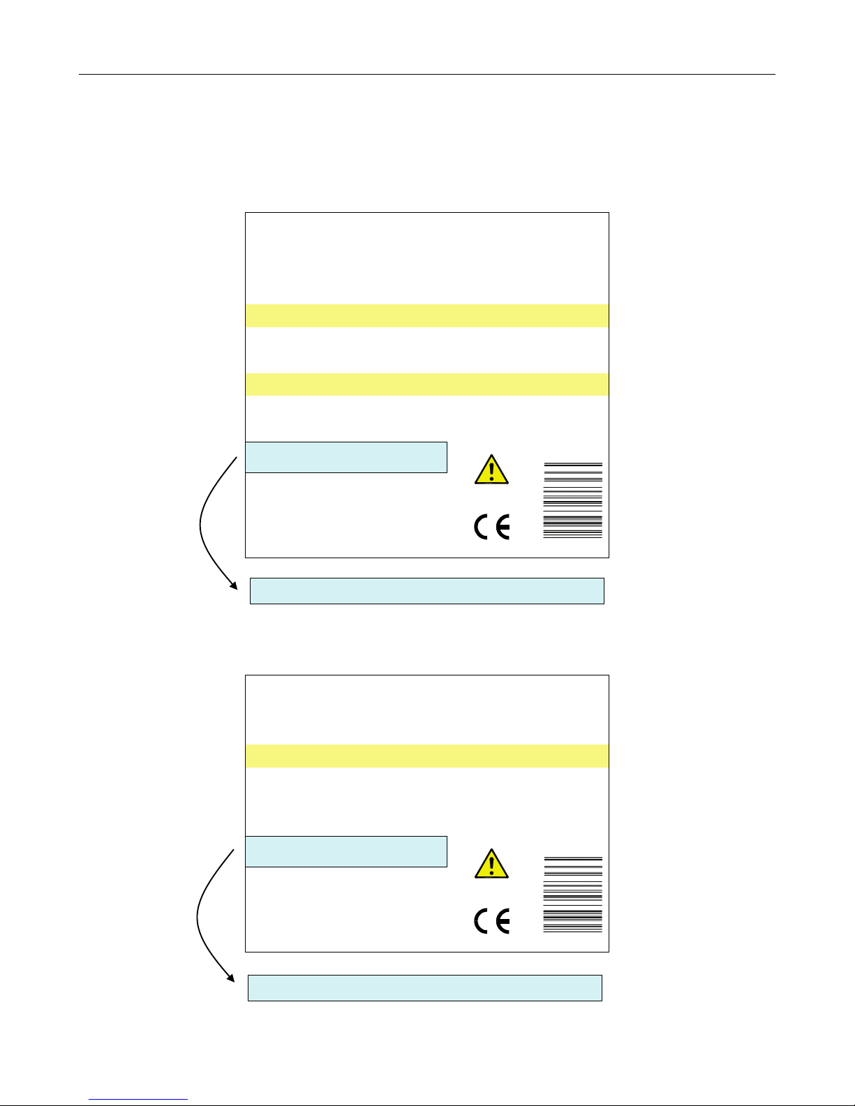
1.1 Sensor unit............................................................................................................................................. 3
1.2 Evaluation unit with user interface (display)........................................................................................... 3
2Content .................................................................................................................................................. 4
3General advice....................................................................................................................................... 6
4Safety instructions.................................................................................................................................. 6
4.1 General safety instructions .................................................................................................................... 6
4.2 Special advice in accordance with the 97/23/EC Pressure Equipment Directive .................................. 9
4.3 Special safety instructions ..................................................................................................................... 9
4.4 Process-dependent hazards................................................................................................................ 10
5Field of application and proper use of the METPOINT®OCV ............................................................. 10
6Technical data ..................................................................................................................................... 12
6.1 METPOINT®OCV sensor unit............................................................................................................. 12
6.2 Evaluation unit with user interface (display)......................................................................................... 13
6.3 EU directives and harmonised standards applied ............................................................................... 13
6.4 Installation requirements...................................................................................................................... 14
6.4.1 Sensor unit........................................................................................................................................... 15
6.4.2 Evaluation unit with user interface ....................................................................................................... 15
6.5 Illustration of the device ....................................................................................................................... 16
6.6 Adjusted operating pressure................................................................................................................ 17
7System and functional description ....................................................................................................... 18
8Transport and storage ......................................................................................................................... 19
9Unpacking............................................................................................................................................ 19
10 Installation............................................................................................................................................ 20
10.1 Place of installation.............................................................................................................................. 20
10.2 Installation diagram METPOINT®OCV with activated carbon adsorber ............................................. 22
10.3 Installation diagram METPOINT®OCV with BEKOKAT ...................................................................... 23
10.4 Installation diagram METPOINT®OCV with oil-free compression ...................................................... 24
10.5 Installation of METPOINT®OCV downstream of an activated-carbon filter ........................................ 25
10.6 Installation diagram bypass installation for METPOINT®OCV............................................................ 26
10.7 Installation steps .................................................................................................................................. 27
11 Start-up ................................................................................................................................................ 35
11.1 General advice regarding the installation............................................................................................. 36
11.2 Procedure settings............................................................................................................................... 37
11.3 Procedure start measurement ............................................................................................................. 43
12 Removal from service and uninstalling................................................................................................ 48
13 Operation ............................................................................................................................................. 48
13.1 Control and display elements............................................................................................................... 49
13.2 General advice for the operation of the METPOINT®OCV ................................................................. 50
13.3 Trouble indications, service indications and note fields....................................................................... 51

Contents
METPOINT®OCV 5
13.3.1 Trouble indications............................................................................................................................... 51
13.3.2 Service indications............................................................................................................................... 52
13.3.3 Note fields............................................................................................................................................ 53
13.4 Measured value memory ..................................................................................................................... 53
13.5 Display of the alarm message ............................................................................................................. 54
13.5.1 Potential-free alarm contact................................................................................................................. 54
13.5.2 Analogue output 4-20 mA .................................................................................................................... 60
13.6 Reading out of the measured values via the Ethernet connection ...................................................... 65
14 Declaration of conformity..................................................................................................................... 66
15 Maintenance and service..................................................................................................................... 68
15.1 Care ..................................................................................................................................................... 68
15.2 Daily check........................................................................................................................................... 68
15.3 Calibration............................................................................................................................................ 69
15.4 Support with regard to any application queries.................................................................................... 69
16 Appendix.............................................................................................................................................. 70

General advice
6 METPOINT®OCV
3 General advice
Please check, prior to reading the operating instructions, whether or not these instructions correspond to the
device by comparing the indications on page 3 with the two type plates (sensor unit and evaluation unit with
user interface).
Read these installation and operating instructions carefully prior to any intervention regarding the measuring
device.
The operating instructions must be accessible at all times at the place of application of the device.
To ensure safe operation, the device must only be operated and maintained in accordance with the
indications in the operating instructions. In addition, the national and operational statutory provisions and
safety regulations, as well as the accident prevention regulations required for the respective case of
application, need to be observed during employment. This applies accordingly when accessories are used.
Non-observance of the installation and operating instructions involves risks for persons and systems.
The sensor unit and the evaluation unit with user interface (display) must not be opened!
Prior to establishing the connection with the electric supply mains, the housing of the evaluation unit and the
sensor unit must be connected with the supplied signalling cable!
System performance tests, installation, setting and service measures must only be carried out by authorised
skilled personnel1.
As a basic principle, device calibration must only be carried out by authorised skilled personnel.
To prevent contamination of the probe and of the sensor unit, allow compressed air to flow off of the
compressed-air system for a short period of time prior to installation.
Stagnant air can lead to an increase of the residual oil content values.
When the system is rendered pressureless, measurement is impossible. An alarm is indicated.
Due to continuous technical development, we reserve the right to implement necessary modifications without
prior notice.
If you have any queries regarding these instructions, please contact BEKO TECHNOLOGIES GMBH.
This symbol stands for actions which can also be implemented by the operators, provided that they are skilled
and authorised accordingly.
It is our aim to offer you an environmentally-friendly measuring device:
Specific measures for reduced energy consumption.
Packaging made of recycled material.
Please support this concern regarding environmental protection by following all advice given.
4 Safety instructions
4.1 General safety instructions
DANGER!
Compressed air!
When applied incorrectly, compressed air represents an extremely dangerous energy source. Never work on
components at the measuring device which are under pressure. Never direct a compressed-air stream at
persons. The user must ensure that the installation of the METPOINT®OCV takes place in compliance with
the instructions in the chapter entitled "Installation".
Make sure that no parts of the measuring devices are under pressure or unintentionally supplied with
compressed air during the implementation of service measures.
1Authorised skilled personnel are persons who are authorised by the manufacturer, with experience and technical training, who are
well-grounded in the respective provisions and laws and capable of carrying out the required works and of identifying and avoiding
any risks during the machine transport, installation, operation and maintenance.
Qualified and authorised operators are persons who are instructed by the manufacturer regarding the handling of the METPOINT®
OCV, with experience and technical training, and who are well-grounded in the respective provisions and laws.

Safety instructions
METPOINT®OCV 7
DANGER!
Overpressure!
Adhere to the indications on the type plate regarding the maximum pressure!
Before starting installation, it is imperative to ensure that the compressed-air line is pressureless!
DANGER!
Supply voltage!
Operation and maintenance of electrically-powered machines and devices must only be undertaken by
correspondingly qualified and authorised personnel. Prior to carrying out service measures, no matter which
type, the following notes must be considered:
Make sure that no parts of the measuring devices are energised and that the measuring devices cannot be
connected with the electric supply mains during service measures.
The device must not be started if the power cables show any damage.
METPOINT®OCV must not be operated if coverings have been removed.
DANGER!
Missing earth connection!
When the earth connection (protective earth) is missing, there is the risk in the event of malfunction, that
contactable, conductive components may carry supply voltage. Touching of such parts leads to an electric
shock with injuries and death.
It is imperative to connect the plant to earth or to connect the protective conductor according to the
regulations.
Do not use plug adapters at the power plug.
Have the power plug replaced by qualified persons, if required.
WARNING!
Unauthorised interventions!
Any modification of the measuring device or of the function parameters which has not been checked and
approved by the manufacturer leads to the development of potential danger sources.
WARNING!
Hot surface!
Personal injury and damage to objects – fire hazard!
Allow the plant to cool down prior to carrying out works on the METPOINT®OCV! Close off accessible areas
and mark them.
DANGER!
Explosion!
Exceeding the explosion limit can lead to explosion involving the risk of injury!
When exceeding the admissible residual oil content of 5 mg/m³, the compressed-air supply should be
interrupted to ensure that the explosion limit will not be reached.
DANGER!
Release of hazardous substances!
Inadmissible gases can lead to health damage and poisoning.
METPOINT®OCV must only be operated with compressed air, free from aggressive, corrosive, caustic,
toxic, flammable and fire-accelerating constituents. Non-compliance with this will involve risks as a result of
the release of harmful gases.
In the event of fire, do not use water to extinguish it (neither in the vicinity of the measuring device nor
directed directly at the measuring device).

Safety instructions
8 METPOINT®OCV
WARNING!
Unauthorised intervention!
Unauthorised interventions may endanger persons or plants and lead to malfunction.
Do not open the housing of the sensor unit or of the evaluation unit!

Safety instructions
METPOINT®OCV 9
4.2 Special advice in accordance with the 97/23/EC Pressure Equipment Directive
The proper use of the compressed-air plant is the basic requirement for safe operation. Therefore, the user must
proceed as follows:
•The measuring device must only be employed within the pressure and temperature range limits indicated by
the manufacturer on the type plate.
•The maximum operating pressure indicated by the manufacturer on the type plate must not be exceeded. It is
the user's task to install the appropriate safety and control devices.
•The METPOINT®OCV must neither be set up in insufficiently ventilated rooms nor near heat sources or
inflammable substances.
•To avoid fractures resulting from material fatigue, the METPOINT®OCV should not be exposed to vibrations
during operation.
•The documents related to the METPOINT®OCV device (manual, operating instructions, manufacturer's
declaration etc.) must be kept safe for future reference.
•No objects whatsoever must be installed at or placed on the METPOINT®OCV and the connecting lines.
WARNING!
Unauthorised intervention!
Unauthorised interventions may endanger persons or plants and lead to malfunction.
Tampering, modification and abuse of the pressure devices is forbidden. Users of the devices need to
observe the local and national pressure equipment regulations in the country of installation.
4.3 Special safety instructions
IMPORTANT!
Overpressure!
Exceeding the maximum pressure can lead to damage in the plant.
Observe the type plate indications regarding the maximum pressure!
IMPORTANT!
Exceeding of the measuring range (red alarm indication)!
Employing the METPOINT®OCV above the indicated measuring range can damage the device!
Observe measuring range of the sensor unit! ≤ 0.01...5.0 mg/m³ (in accordance with ISO 8573-1)
IMPORTANT!
Overheating!
Overheating will destroy the sensor unit and the evaluation unit.
Observe the permissible storage and transport temperature, as well as the permissible operating temperature
(e.g. protect the measuring device against direct sunlight).

Field of application and proper use of the METPOINT® OCV
10 METPOINT®OCV
4.4 Process-dependent hazards
CAUTION!
Harmful hydrocarbons!
Harmful hydrocarbons can exist in the ductwork.
For example:
- Hydrocarbons and other particles which are toxic or otherwise dangerous to health.
- Particles which are contained in high-temperature gases.
As long as the process conditions are not absolutely safe, corresponding preventive measures must be
undertaken, such as the use of a respiratory mask or purging/detoxification of the ductwork, prior to any
intervention in the ductwork for maintenance or installation purposes.
Ensure that the ductwork is pressureless prior to carrying out any installation or dismantling works. If you are
unsure in certain cases, please contact the responsible safety representative on location and/or read the local
safety regulations.
DANGER!
Release of hazardous substances!
Inadmissible gases can lead to health damage and poisoning.
METPOINT®OCV must only be operated with compressed air, free from aggressive, corrosive, caustic, toxic,
flammable and fire-accelerating constituents. Measurements in aggressive, corrosive, caustic, toxic,
flammable and fire-accelerating media are not allowed.
5 Field of application and proper use of the METPOINT®OCV
The METPOINT®OCV devices serve for the stationary measurement and monitoring of the vaporous and gaseous
residual oil content in compressed air (ISO 8573:2001). Any other use is considered improper.
The manufacturer shall not be liable for the consequences of improper use; the user alone is responsible for all risks
that may arise.
The proper employment and use of the METPOINT®OCV according to directions requires the exact compliance with
the installation instructions, in particular in respect of:
•The place of installation, installation conditions
•The supply voltage and frequency
•The pressure, temperature and humidity of the inlet air
•The ambient temperature
The device is supplied as accepted in the factory. The user only needs to establish the connections with the supply
mains and interconnect the components, which is described in the following chapters.
WARNING!
Employment for the prevention of dangerous conditions!
A device of the METPOINT®OCV series must not be employed as the sole means of preventing dangerous
conditions at machines and plants.
Machines and plants must be constructed in such a manner that defective conditions do not lead to a
dangerous situation for persons or plants.
WARNING!
Improper use!
The METPOINT®OCV measuring devices offer state-of-the-art technology and are operationally safe.
Residual risks may emanate from the measuring device when improperly employed and operated by
untrained personnel.

Field of application and proper use of the METPOINT® OCV
METPOINT®OCV 11
The METPOINT
®
OCV measuring devices must only be used by qualified and authorised personnel and
exclusively in accordance with the technical data.

Technical data
12 METPOINT®OCV
6 Technical data
6.1 METPOINT®OCV sensor unit
Measuring medium: Compressed-air free from aggressive, corrosive, caustic, toxic, flammable and fire-
accelerating constituents
Measurand: Residual oil content in mg oil / standard m³ (based on 1.0 bar, +20°C, 0% relative humidity)
in accordance with ISO 8573-1
Identifiable substances:
Polyalphaolefins, aromatics
Aliphatic hydrocarbons
Hydrocarbons
Functional hydrocarbons
Ambient temperature: +5°C to +45°C
Compressed-air
temperature at the inlet:
+5°C to +55°C
Operating overpressure: 3 bar(g) to max. 16 bar(g) --> see type plate (cf. also page 3)
Measuring gas humidity: ≤40 % rel. humidity, pressure dew point max. +10°C, non-condensable humidity
Measuring range: ≤ 0.01 – 5.000 mg/m³ residual oil content (in accordance with ISO 8573-1)
Measuring accuracy: The measuring accuracy is 0.003 mg/m³.
Detection limit (residual
oil): 0.0006 mg/m³
Amount of measuring
gas: Approx. 2 to 3 standard litres/minute related to 1.0 bar absolute and +20°C (expanded)
The amount of measuring gas depends on the operating pressure.
NOTE!
The measuring gas is released into the environment. Please consider the resulting
concentration values at the place of installation of the METPOINT®OCV. Ensure sufficient
ventilation.
Fields of application: Downstream of an activated-carbon filter (see installation instructions Chapter 10.5)
Downstream of an activated-carbon adsorber
Downstream of a BEKOKAT (catalytic converter)
Downstream of an oil-free compressor
Each with corresponding upstream filtration and drying
Dimensions: 487 x 170 x 120 mm (W x H x D)
Weight: Approx. 6.6 kg
Power supply: Version 1: 230 V AC 50 Hz +/- 10%
Version 2: 115 V AC 60 Hz +/- 10%
Max. operating current: 0.3 A at 230 VAC
Power consumption: 41 W
External fusing: 2.0 A, slow, recommended
Power cord:
Max. cladding diameter: 6.5 mm, strand cross section: 0.75 mm²,
with safety plug and PE protective earthing
Protection class: Standard IP 20
Connection probe: G 3/8” internal thread
Probe type 1: DN 20 to DN 40 ¾“ to 1 ½“
Probe type 2: DN 50 to DN 80 2“ to 3“
Probe type 3 : > DN 80 produced in accordance with the customer's
requirements

Technical data
METPOINT®OCV 13
6.2 Evaluation unit with user interface (display)
Dimensions: 230 x 200 x 120 mm (W x H x D)
Weight: Approx. 3.6 kg
Protection class: Standard IP 54
Operating temperature: +5..+50 °C
Storage temperature: +5..+50 °C
Resistance to climatic
conditions:
Rel. humidity ≤75% annual mean without dew
Power cord: Max. cladding diameter: 6.5 mm, strand cross: 0.75 mm²,
with safety plug and PE protective earthing
Outputs: Potential-free change-over contact, 230V/AC 5A or 24V/DC 5A
optional 4….20 mA
Power supply: Version 1: 230 V AC 50 Hz +/- 10%
Version 2: 115 V AC 60 Hz +/- 10%
Internal fusing: 1.0 A, slow (T1A / 250V)
Max. operating current: Max. 0.22 A
Power consumption: Max. 50.6 VA
Memory: 2 GB internal memory
6.3 EU directives and harmonised standards applied
2006/95/EC Low-Voltage Directive
2004/108/EC Directive about the electromagnetic compatibility, EMC
EN 61010-1 Safety requirements for electrical equipment for measurement, control and laboratory
use
EN 61326-1 Electrical equipment for measurement, control and laboratory use
EMC requirements

Technical data
14 METPOINT®OCV
6.4 Installation requirements
Installation requirements: Vertically into the rising main via oil and grease-free measuring section
Alternatively via heated analysis hoses
In general, the requirements on homogeneous flow conditions and concentrations are met when sampling takes place
in a straight pipe section with an inlet section of at least five hydraulic diameters (5 x DN) and an outlet section of three
hydraulic diameters (3 x DN). In addition, the pipe section must have a constant shape and a constant cross-section.
Inlet zone: 10 x DN (min. 200 mm) in accordance with ISO 8573-2
Outlet zone: 3 x DN (min. 100 mm) in accordance with ISO 8573-2
For the measuring sections made by BEKO TECHNOLOGIES or for measuring sections which are manufactured
according to the specifications of BEKO TECHNOLOGIES, we recommend guide values for the minimum flow of
the compressed air in the measuring sections, to ensure representative sampling. You will find these guide
values in a table in the Appendix.
Minimum flow: See table in the Appendix
Measuring gas INLET
Dimensions

Technical data
METPOINT®OCV 15
6.4.1 Sensor unit
You will find the dimensioning of the mounting holes in the Appendix.
Please make sure to observe the servicing height when choosing the place of installation.
Servicing height with probe type 1: 500 mm
Servicing height with probe type 2: 700 mm
6.4.2 Evaluation unit with user interface

Technical data
16 METPOINT®OCV
6.5 Illustration of the device
1 - Sensor unit
2 - Evaluation unit with user interface (display)
3 - Sampling probe
4 - Union nut
5 - Screw-connection body with G 3/8” external thread
6 - Stationary seal ring (2x)
7 - User interface / touchscreen
8 - Power supply cable for the sensor unit
9 - Power supply cable for the evaluation unit
10 - Signalling cable
11 - Connection signalling cable sensor unit
12 - Connection signalling cable evaluation unit
13 - On / off switch incl. indicator (green LED)
14 - Connection analogue output 4-20 mA (see Chapter 13.5.2, page 60)
15 - Connection Ethernet
16 - Measuring-gas connection "M"
19 - Connection potential-free alarm contact (see Chapter 13.5.1, page 54)
20 - Specification regarding the adjusted operating pressure

Technical data
METPOINT®OCV 17
17 - Calibration-gas connection "C" (optional)
18 - Zero-air connection "Z" (optional)
6.6 Adjusted operating pressure
When delivered, the METPOINT OCV has been prepared and adjusted to the operating pressure indicated by you. You
will find this setting below the type plate of the sensor unit.
Please contact us in the event that your operating conditions have changed. The BEKO service team will then adjust
your device correspondingly.
EINGESTELLTER ARBEITSDRUCK
ADJUSTED WORKING PRESSURE
PRESSION REGLÉE À
7.5 bar(g)

System and functional description
18 METPOINT®OCV
7 System and functional description
The METPOINT®OCV was developed for the detection of vaporous and gaseous hydrocarbons in compressed air free
from aggressive, caustic, toxic, flammable and fire-accelerating constituents.
When the stipulated installation requirements are met, aerosols should not exist at the inlet into the METPOINT®OCV
device. Irrespective of this, oil components in the form of aerosols with a concentration of max. 5 mg/m3are detected
and indicated. However, isokinetic sampling does not take place (identical velocity at the place of withdrawal and in the
measuring device), as this is not a constituent part of DIN ISO 8573 for oil vapour. The aerosol content would therefore
be determined underkinetically with the result that a higher measured value than the actual one is indicated. As far as
aerosols are concerned though, there is a danger that the measuring device will be contaminated very strongly at high
concentrations and that, as a result, no usable data can be acquired. This condition is identified by the sensor
electronics and indicated as a failure on the display. Simultaneously, information about necessary measures is provided
to the customer, e.g. cleaning measures or purging with zero air.
The METPOINT®OCV consists of two major components, the sensor unit with sampling probe and the evaluation unit
with user interface (display). Via a signalling cable with a length of 5 m, the sensor unit is connected with the evaluation
unit. The sampling probe is installed centrically from the top in the rising main, so that the probe takes compressed air
in the centre of the compressed-air flow to be monitored.
The sensor of the METPOINT®OCV functions according to the proven and reliable principle of photoionisation.
The measuring principle of a photoionisation detector PID is based on the ionisation of the gas molecules through UV
radiation and registration of the resulting ion current. The normal components of the compressed air (oxygen, nitrogen,
carbon dioxide, argon, water etc.) are not ionised by the UV lamp. In contrast, hydrocarbons are reliably ionised. The
strength of the ion current is directly proportional to the concentration of the ionised molecules. The electrical signal is
measured, electronically amplified, and shown on the display as the total of the measured substances.
For corresponding operational reliability, the performance of the sensing technology is continuously monitored during
the measurements. In the event that a defined safety limit value has not been reached, an alarm is activated which
informs the user that the device needs to be checked by BEKO. A clear text will appear which is highlighted in red.
The PID sensor shows the overall concentration of all photoionisable compounds contained in the sample and does not
differentiate between individual components/substances. Even hydrocarbon compounds with less than six carbon
atoms (<C6) can be detected, e.g. isobutene. However, this requires these molecules to be ionised by the UV lamp.

Transport and storage
METPOINT®OCV 19
8 Transport and storage
•During the transport, the permissible temperature of 50°C (storage temperature) must not be exceeded.
•Transport should only take place in the original packaging.
•Protect the device against falls or excessive vibrations.
SCC0001
Protect the device against atmospheric influences even
when packaged.
The METPOINT®OCV must be protected against falls and
excessive vibrations at the place of storage.
Store the METPOINT®OCV in the original packaging in a
closed, frost-protected room at a maximum temperature of
+50°C and an air humidity of max. 75%.
If the storage period exceeds 12 months, you should contact
the manufacturer.
The installation and operating instructions should be kept
with the device!
9 Unpacking
After having checked the soundness of the outer packaging, set up and unpack the device in close proximity to the
selected places of installation of the sensor and the evaluation unit.
For the connection to the sensor unit, do not touch the probe without wearing oil- and grease-free gloves
(textile gloves are recommended). A fingermark on the probe or in the measuring zone can affect the
measuring results or lead to false measurements.
Handle the device with due care.
Strong shocks cause irreparable damage.
When not directly employing the METPOINT®OCV, keep the device in the original packaging!
The installation and operating instructions should be kept with the device!
The packaging consists of recycled material.
Dispose of each individual material separately in accordance with the local provisions.

Installation
20 METPOINT®OCV
10 Installation
For safe operation and functionality, all indications and advice given in the installation and operating instructions must
be adhered to. In addition, the statutory provisions and safety regulations required for the respective case of application
need to be observed during employment. This applies accordingly when accessories are used.
10.1 Place of installation
CAUTION!
Ambient conditions!
Choose a place of installation which cannot impair the specified function of the METPOINT®OCV.
Installation in ambient conditions which are not suitable affects the measuring results and can lead to
malfunctions and damage to the sensor.
The device must not be operated in an explosive environment or in areas with high fire danger, near
aggressive chemicals and superheated steam, in a very hot environment or in strongly contaminated zones.
Do not use water for fire fighting on or in the vicinity of the METPOINT®OCV.
Other manuals for METPOINT OCV
2
Table of contents
Other Beko Measuring Instrument manuals

Beko
Beko METPOINT User manual

Beko
Beko BEKOMAT 12 KW User guide

Beko
Beko METPOINT OCV User guide

Beko
Beko DP 109 User guide

Beko
Beko METPOINT BDL portable User guide

Beko
Beko FLM SF53 User manual

Beko
Beko METPOINT FLM SF13 User manual

Beko
Beko FLM SF53 Owner's manual

Beko
Beko METPOINT BDL compact User manual