Bel-art B60901-0100 User manual

CONTENTS
TITLE PAGE
1. Introduction………………………………………………………………….…………….1
2. Specifications……………………………………………………………………………...1
3. Symbol Definition and Button Location………......................................................2
4. Operation Instructions……………………….…………………..................................3
4.1 Power-Up……………...........................................................................................3
4.2 Connection of the Temperature Probe………....................................................3
4.3 Selecting the Temperature Scale……………..……………………………………..3
4.4 READ Operation…………………………………………………………………..…..3
4.5 Backlit Operation…………………………………………………………………..3
4.6 Relative Operation……………………………………………………………............3
4.7 Memory Operation………………………………………………………...................3
4.8 MAX/MIN Operation………………………….……………………………................3
4.9 Auto Power-Off………………………………………………………………………4
4.10 Low Battery Condition………………………………………..... …………………..4
5. Temperature Measurement……………………………………....... …………………..4
6. Setting the Time…………………………………………………………........................5
7. Clearing Memory………………………………………………………………………….5
8. Temperature Meter Calibration Setup ……….………………………………………..6
9. Power Preparation……………………………………………………………..…….......7
10. Maintenance .….………………………………………………………………...………7
11. Temperature Probe.……………………………………………………………............8

RTD THERMOMETER
1
1. INSTRUCTION
This instrument is a digital thermometer for use with platinum-type temperature sensor.
Temperature indication follows IEC751 temperature table for PT-type sensor.
2. SPECIFICATIONS
Numerical Display: 5 digital liquid crystal displays
Measurement Range: -100°C to 400°C; -148°F to 752°F
Resolution: 0.01°C; 0.02°F;
Sensor types:
Platinum resistance temperature sensor for pt-100 4 wires.
ALPHA=0.00385
Environmental:
Operating Temperature and Humidity:
0°C to 50°C (32°F to 122°F) ; 0 to 80% RH
Storage Temperature:
-10°C to 60°C (14°F to 140°F); 0 to 80% RH
Altitude up to 2000 meters.
Accuracy: at ( 23 ± 5°C; 73± 9°F )
Range
Accuracy
-100°C ~ 400°C
±(0.05% reading + 0.1°C)
-148°F ~ 752°F
±(0.05% reading + 0.2°F)
Temperature Coefficient:
For ambient temperatures from 0°C ~ 18°C and 28°C ~ 50°C, for each °C ambient below 18°C or
above 28°C add the following tolerance into the accuracy spec.
0.005% of reading + 0.01°C ( 0.005% of reading + 0.02°F )
Note:
The basic accuracy Specification does not include the error of the probe please refer to the
probe accuracy specification for additional details.
Sample Rate: 2 times per second
Dimension: 185 x 65 x 36 mm (meter only)
Weight: 360g Approx.
Power requirement:
9V Battery;
AC adapter: 9V DC(7 to 10V Max.)/20mA Min (Plug Diameter: 3.5mmx1.35mm)
Battery Life: Approx. 100hours
Standard Accessory:
Pt-100 Probe (class A), Instruction manual, 9V Battery, carrying case.
Optional Accessories: AC adapter.

RTD THERMOMETER
2
3. SYMBOL DEFINITION & BUTTON LOCATION
: The Battery
is not sufficient for proper operation.
MIN
: The Minimum value is being displayed
MAX
:
The Maximum value is being displayed
:
Auto Power-Off is enabled.
REL
: The reading is under Relative Mode.
°C °F
: Centigrade and Fahrenheit indication.
-
:
A below zero reading
m-d
: month
-day
h:m
: hours; minute
:
Readings are being logged.
:
Logged readings are display.
○
1
Pt type temperature sensor connector
○
7
°C , °F control button
○
2LCD display ○
8Read button
○
3
Power ON/OFF and Back light button
○
9
External DC 9V power supply jack
○
4Relative readout button ○
10 Tilt stand
○
5Memory button ○
11 Battery Compartment
○
6MAX/MIN control button
RTD THERMOMETER
3
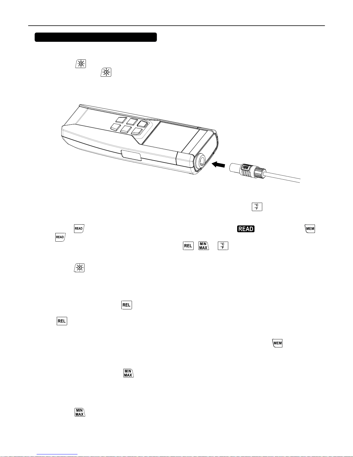
4. OPERATION INSTRUCTIONS
4.1 Power-Up
Press the “ ” button to turn ON the thermometer
Press and hold the “ ” button for 3 seconds to turn OFF the thermometer.
4.2 Connection the Temperature Probe
For measurement, plug the temperature probe into the input connector.
4.3 Selecting the Temperature Scale
When the meter is first powered on, the default scale will show. The default is set on the Celsius
(°C) scale. The user may change it to Fahrenheit (°F) scale by pressing the button.
4.4 READ Operation
Press the button to view the logged readings. The display shows “ ”. Press either the
or button to scroll through the logged readings. The display shows each logged reading, its’
time stamp and memory location. Press either the , or button to exit the READ mode.
4.5 Back light Operation:
Press the button to turn on the back light. Press it again to turn it off.
NOTE: The meter will turn the back light off if there is no button pushed for 30 seconds.
4.6 Relative Operation:
When the user presses the button, the meter will memorize the present reading and the
difference between the new reading and the memorized data will be shown on the display. Press
the button again to exit the Relative operation.
4.7 Memory Operation:
The thermometer stores a single set of readings in memory each time the button is
pressed. The thermometer will hold 99 readings.
4.8 MAX/MIN Operation:
When the user presses the button, the meter will enter the MAX/MIN mode. Under this mode
the maximum and minimum values are kept in the memory simultaneously and updated with every
new data.
When the MAX symbol is display, the Maximum temperature is shown on the display.
Press the button again, the MIN symbol and the minimum temperature reading are shown on
the display.
RTD THERMOMETER
4
Press the button again, the MAX and MIN symbols will blink together. All the data is updated
in the memory and the reading is the present temperature.
The user may press the button to circulate the display mode among these options.
To exit the MAX/MIN mode, press and hold the button for two seconds.
NOTE: When the meter is in the MAXMIN operation, the and buttonsare disabled.
4.9 Auto Power-Off:
By default, when the meter is powered on, it is in auto power-off mode. The meter will power itself
off after 30 minutes if no button is pushed.
To disable the auto power-off, press and hold the button and then power on the meter. There
will be two successive beeps to confirm that auto power-off is disabled.
4.10 Low Battery Condition:
The temperature meter low battery indication is:
Low battery. Replace the batteries.
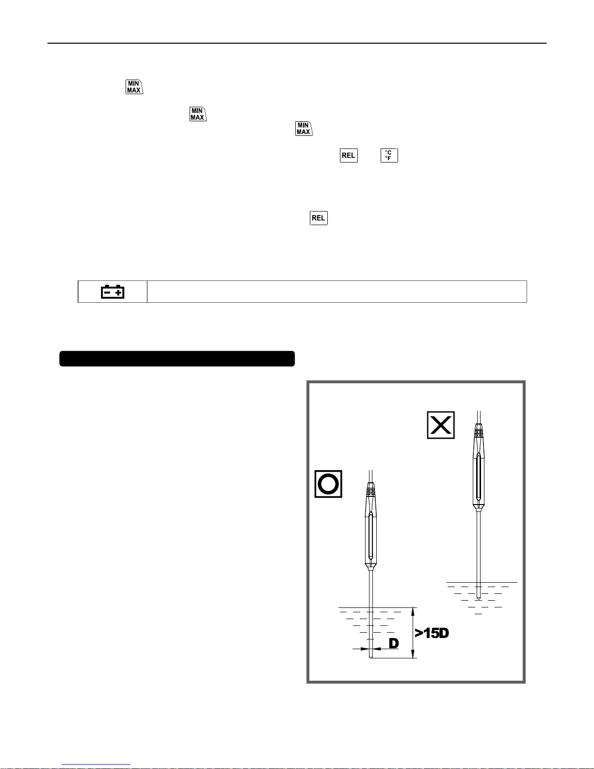
5. TEMPERATURE MEASUREMENT
5.1 Correct Measurement Method:
THE TEMPERATURE SENSOR IS LOCATED AT THE END OF
THE METAL SHEATH OF THE TEMPERATURE PROBE.
TO ACCURATELY TEST INTERNAL TEMPERATURE,INSERT
THE PROBE INTO THE SPECIMEN TO A DISTANCE AT LEAST
15 TIMES THE DIAMETER OF THE SHEATH.
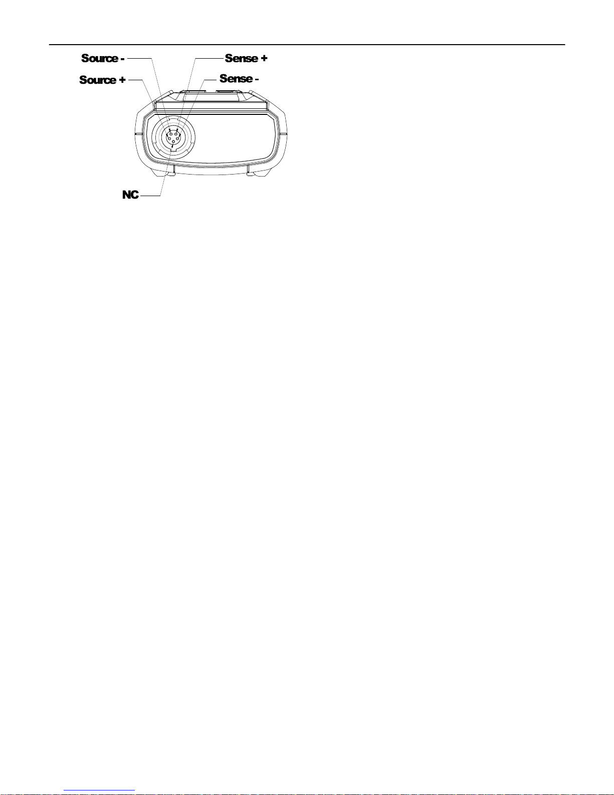
5.2 Connector Configuration:
RTD THERMOMETER
5
RTD THERMOMETER
6
6. SETTING THE TIME
6.1To enter into the meter setup mode, press and hold the button, then power on the meter.
6.2 Press the button to enter “Time setting” mode. The right two digits will blink.
6.3 Press either the ▲or ▼button until the display shows the correct year, then press the
button to select. The left two digits will blink.
6.4 Press either the ▲or ▼button until the display shows the correct month, then press the
button to select. The right two digits will blink.
6.5 Press the ▲or ▼button until the display shows the correct day, then press the
button to select. The left two digits will blink.
6.6 Press the ▲or ▼button until the display shows the correct hour (24-hour format), then
press the button to select. The right two digits will blink.
6.7 Press the ▲or ▼button until the display shows the correct minutes, then press the
button to store the time in memory.
Note: Holding down either the ▲or ▼button will cause the number to change more quickly.
7. CLEARING MEMORY
When the memory is full, “MEM” will appear and blink on the display and logging stops.
To enter into the “Clear memory” mode, press and hold the button, then power on the meter.
The display shows the number from 5 decreasing to 0.

RTD THERMOMETER
7
8. TEMPERATURE METER CALIBRATION SETUP
The below table diagram shows each button function when in the
calibration mode.
Note: Turn the Auto Power-Off off before attempting the following
SETUP. Setup mode is cancelled if the button is pressed during
the procedure.
8.1 Temperature Calibration
Place the temperature probe in a known, stable temperature environment. Allow the reading to
stabilize. In the “Setup” mode, change the offset until the display reading matches the calibration
temperature.
8.1.1 To enter the setup mode, press and hold the and button, then power on the meter
8.1.2 Press the button to enter the calibration mode. (in 3 seconds)
8.1.3 Press the button to enter the calibration mode. (in 3 seconds)
8.1.4 Press the or button to confirm the present Temperature value.
8.1.5 Press the button twice to confirm selection.
Note: To abort during the process, press the button to exit calibration mode.
8.2 Recall Default factory setting value
8.2.1 To enter the setup mode, press and hold the and buttons, then power on the meter.

RTD THERMOMETER
8
8.2.2 Press the button to enter the calibration mode. (in 3 seconds)
8.2.3 Press the button to enter the recall mode. (in 3 seconds)
8.2.4 Press the button to confirm reverting back to the “Default factory setting value”
8.2.5 Press the button to confirm selection.
Note: To abort during the process, press the button to exit calibration mode.
9. POWER PREPARATION
9.1 Battery Loading
Remove the battery cover on the back and insert one 9V battery.
9.2 Battery Replacement
When the battery voltage drops below the operating voltage, the “Low battery indicator” will
appear. Replace a 9 Volt battery immediately to ensure the unit functions properly.
9.3 AC Adapter Connection
When the AC adapter is used, insert the plugs of the adapter into the DC9V connector on the side
panel.
Note: When the AC adapter is connected while a battery is inserted, the unit will be powered from the
adapter (the AC adapter has priority).
10. Maintenance
In order to ensure the accuracy of the thermometer for a longer period of time you should calibrate
it once a year.
Clean the device and the window of the display with a clean, lint-free, antistatic and dry cleaning
cloth.
Do no use cleaning agents that contain carbon, benzenes, alcohol or anything similar to clean the
product since these substances can damage the surface of the measuring instrument. Moreover, the
fumes from these cleaning agents are hazardous to your health and explosive. Do notuse tools with
sharp edges, screwdrivers, metal brushes or anything similar to clean the device.
RTD THERMOMETER
9
11. Temperature Probe
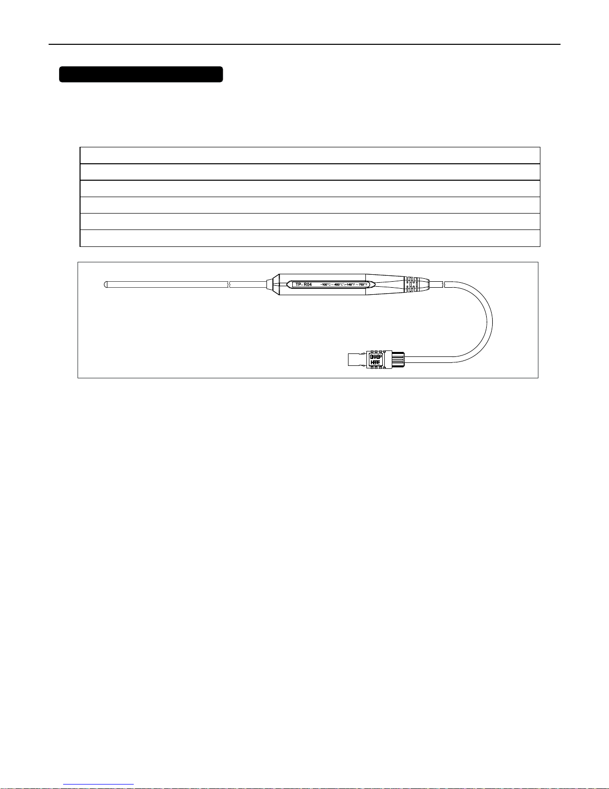
11.1 Piercing type temperature probe.
11.2 Piercing type temperature probe Specification:
Sensor Type
Platinum resistance thermometer sensor Pt 100(4 wires)
Accuracy
IEC751, class A (t: measurement temperature)
Measurement Range
-100 to 400
°
C
Temperature Sensor Dimensions
Approx.
∅
5.0mm(
∅
0.2”)
Temperature Sensor Length
Approx. 230mm(9.05”)
Cable Length
Approx. 1500mm(59.0”)

RTD THERMOMETER
10
Statement of Traceability
Display serial number _____________
Probe serial number _____________
Date of report: _____________
The precision display and probe identified above was compared to a high precision digital
standard, traceable to NIST (National Institute of Standards and Technology). The probe conforms
to the accuracy prescribed by DIN IEC 751, Class A (permissible deviation is ºC = ± (0.15 + 0.002 [t])
where [t} is the temperature value in ºC) and the display accuracy is ± (0.05% reading + 0.1ºC).
The standard serial number calibrated by NIST is:
ASL F250, 1285-028-415 for -80 to 400ºC
H-B Instrument Company’s laboratory is accredited in accordance with the international Standard
ISO/IEC 17025:2005 by A2LA. H-B’s laboratory also meets the requirement of ASNI/NCSL Z540-1-
1994.
Please visit www.hbinstrument.com for the uncertainty of measurement associated with our
calibration system. It is available on our scope of accreditation. Certification at custom
temperature points is available for an additional charge. Contact us for details.
Richard Jackson
Production Manager
H-B Instrument Company
Triple Accredited/Registered
ISO 9001:2008 Registered
ISO 14001:2004 Registered
ISO/IEC 17025:2005 Accredited
For more information call (610) 489-5500 • Fax (610) 489-9100
info@hbinstrument.com • www.hbinstrument.com
Table of contents
Other Bel-art Thermometer manuals


