PNI MAB300 User manual

PNI MAB300
Swing gates opener
Kit automatizare porti batante
EN User manual ............................................. 2
RO Manual de utilizare ................................... 17


3User manual
English
Warnings
»Read this manual carefully before assembling and commissioning the
product. Incorrect installation and use can lead to product damage,
personal injury and property damage.
»This product should be installed by qualified personnel only in compliance
with the safety rules. Installation by unskilled personnel leads to product
malfunction and personal injury.
»Disconnect the general power source before installing the product or
maintenance work.
»In case the electric cable is damaged, replace it with an entire one and well
insulated to avoid producing an electric shock.
»Do not allow children or other persons to stay in the gates opening area
when they are in action.
»Do not install the product in environments with corrosive, flammable or
explosive substances.
»Do not install the engine in an area where the public could have access to
the manual gate actuation key.
Required tools
Electric drill
and drill bits
Socket set Spanner set Soldering iron
(recommended)
Voltmeter
(recommended)
Screwdriver set Electrical tape Wire cutter
and stripper
G-Clamp

User manual 4
English
Included accessories
Description of swing gate opener

5User manual
English
1. Rear bracket
2. Front bracket
3. Extendable arm (300 mm)
4. Motor box
5. Power cable
Open the gate manually
1. Gates
2. Manual spanner
3. Piston motor
Release by spanner then lift it and separate the motor from the gates.

User manual 6
English
Functions
»In case of power failure: Use the manual spanner, separate the piston
motor from the gate and open or close the gates manually.
»When gate is obstructed: If, as they open, the gates encounter an
obstacle, they stop.
»Optional, the controller can be connected to a solar system, a warning
lamp, a photocell, a backup battery, an access keypad or other access
control devices.
»Gentle start: the system has a gentle opening function at startup.
»Auto closing: the system has an automatic closing function with adjustable
closing time.
»Single or dual gates: the system can be installed on double or single gates.
»Multiple remote transmitters: the system supports several extra remote
controllers.
»Backup battery: a 24V backup battery can be connected (the backup
battery is not included).
»Smooth noiseless operation: the system can be configured for smooth
noiseless operation.
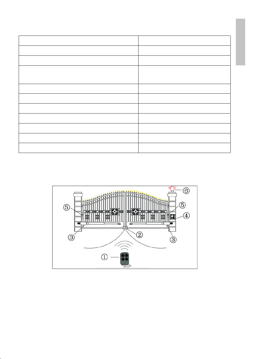
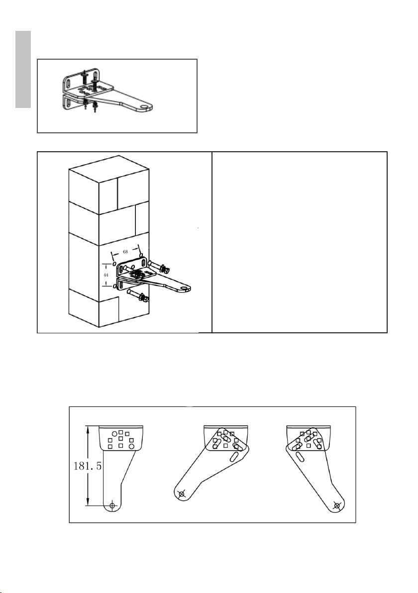
»The system can be configured to enable open condition as default, or
close condition as default depending on the placement of the provided
brackets.

7User manual
English
Technical specifications
Supply voltage 230VAC±10%
Motor voltage 24VDC 40W
Rotation speed 200 rpm
Maximum opening length
of the piston arm
300 mm
Piston elongation speed 1.6 cm/sec.
Maximum length of a gate 2.5 m
Maximum opening angle 110°
Continuous operating time 5 min.
Maximum weight of a gate 200 kg
Water protection class IP55
Working temperature -26°C ~ +60°C
Installation instructions
1. Remote control
2. Rubber stopper
3. Swing gate opener motor
4. Control unit
5. Photocell electric sensor
6. Gate opening warning light (optional)

User manual 8
English
Rear brackets installation
• Make 4 holes in the wall of 8 mm
diameter.
• Insert 4 concrete bolts (included
in the package) into the holes.
• Position and secure with the
included screws the bracket for
the piston motor.
Note: If you have metal poles, you can
weld the brackets.
Adjusting dierent angles of rear bracket

9User manual
English
Warnings
Left image: the power cord and the drain hole are correctly positioned.
Right image: incorrectly positioned power cord and drain hole.
The power cord must not be above the engine body. In the opening motion
of the gate, the cable could be caught and pinched presenting a risk of short
circuiting.
1. Bracket
2. Lock pin
3. Drain hole
4. Power cable
Front brackets installation

User manual 10
English
1. Drill in the gate 2 holes of 10.2 mm each to a distance of 68 mm one
from each other.
2. Fix the bracket in the holes.
3. Fix the motor piston to the front bracket using screws (these are not
included as they vary depending on the thickness of the gate).
4. Insert the locking nut and the washers.
Brackets installation height
Make sure that the height of installation of the rear bracket is equal to the
height of installation of the front bracket. Performing an assembly based on
inaccurate measurements can lead to problems in the operation of the piston
arm. Also, the opening and closing force will be reduced. Large dierences
in height between the two brackets can even burn the motor and the piston
arm.

11 User manual
English
Sistem configuration Normal Closed
Installation dimensions
You can adjust the opening angle of the gate according to the dimensions in
the table below:
The values of columns A, B, C, E and L are expressed in mm.
The values of column D are expressed in degrees.
Control board wiring diagram
Technical parameters:
»Power supply voltage of the control unit: 24 V. A 24V backup battery can
be installed (not included).
»Can work with double gates.
»Supports up to 120 remote controls.
»Motor specifications: 24V DC x 2.

User manual 12
English
1 2 3 4 5 6 7
8 9
10
11 12 13 14 15 16 17 18
19 20 21 22
2324
25
26 27 28
29
1. 2SIDE: for connecting any external device that controls double gates
2. COM: for connecting the “ground” of external devices
3. 1SIDE: for connecting any external device that controls a single gate
4. SWHIPE CARD: for connecting any external device that controls the
gate opening
5. COM: for connecting the “ground” of external devices
6. IR terminal: for connecting the photoelectric sensor
7. 12V DC output: for connection of the photoelectric sensor (DC current
output ≤200mA)
8. 24V battery output: for connecting a backup battery (+)
9. 24V battery output: for connecting a backup battery (-)
10. 24V DC output: for connecting an external device, such as photoelectric
sensor, maximum consumption 1A
11. GND: or connecting the “ground” of external devices
12. 24V DC output: for connecting the warning lamp (+)
13. 24V DC output: for connecting the warning lamp (-)
14. 24V DC output: NF terminal for electric lock connection
15. COM: for connecting the “ground“ of the electric lock
16. 24V DC output: NA terminal, for connecting a magnetic lock
17. Alarm output 24V DC
18. Alarm output 24V DC
19. and 20. The Motor1 terminal is used to connect the motor 1 installed on
the gate that first closes and then opens. Connect here the first red wire

13 User manual
English
(counted from left to right)
21. and 22. The Motor2 Delay terminal is used to connect the motor 2
installed on the gate that first opens and then closes. Connect here the
first blue wire (counted from left to right). NOTE: If used for a single
gate, connect the motor to the Motor2 Delay terminal
23. 24V AC input: for transformer connection (+)
24. 24V AC input: for transformer connection (-)
25. Digital screen for displaying the settings
26. INC+ used to increase values during settings
27. FUN is for saving the settings
28. DEC- used to lower values during settings
29. Pair button for adding / removing remote controls
Remote control
Button 1: to open a single gate
Button 2: to open a double gate
Button 3: to trigger an alarm
Pairing a remote control
1. Press the LEARN button on the mainboard for a second, the indicator
LED will turn o, which means you have entered the learning mode
2. Press any key on the remote control for more than 2 seconds; on the
digital display on the board the remote control number will be displayed,
and the indicator light will flash 4 times followed by a short beep. The
remote control was successfully learned.
Note: If after pressing the LEARN key, the system receives no signal for 5 seconds,
the LED indicator will turn back on and the system will exit the pairing mode.
Removing a remote control
Press and hold the LEARN button on the mainboard for 5 seconds, a short
beep will be heard and the indicator light will turn on to confirm the remote
control’s erasure.

User manual 14
English
Settings
After power on, digital display will self-check from 00-99 with buzzer sound.
If indicator LED lights on, and the buzzer stops, it means the system is normal
working condition.
Basic operation
Press and hold the FUN button until PO appears on the screen. You have now
entered the settings menu. Use the INC + and DEC + buttons to navigate
the menu or to increase and decrease numeric values. Press the FUN button
to save the settings. You will hear a confirmation beep. After saving the data
on the screen, the menu where you made the lastest settings will be displayed.
To go to the next menu, press the INC + and DEC + buttons to navigate
through the menu and the FUN button to enter the desired menu.
After you set the value of P0 and pressed the FUN button to save it, P0 will
keep showing on the screen. If you want to set P1, press the INC + button, P1
will appear on the screen and then FUN to enter the P1 settings.
If you want to exit the menu, press the LEARN button.
1. Smooth start time setting (P0)
P0 appears on the digital display. Options available between 0 and 6 sec. The
value 0 disables this function. Use the INC + button to increase the value by
one unit and DEC- to decrease the value. Press FUN to save the data. The
factory value is 2 seconds.
2. Setting the level of stall force
»P1 on the display, the device is set to low speed stop force for Motor1.
There are optional values from 0 to 20; After choosing the value, press
the FUN button to save the data. (factory setting is 6).
»P2 on the display, the device is set to high speed stop force for Motor1.
There are optional values from 0 to 20; After choosing the value, press
the FUN button to save the data. (factory setting is 10).
»P3 on the display, the device is set to low speed stop force for Motor2,
optional values from 0 to 20. After choosing the value, press the FUN
button to save the data (factory setting is 6).

15 User manual
English
»P4 on the display, the device is set to the high speed stop force for the
Motor2. There are optional values from 0 to 20. After choosing the value,
press the FUN button to save the data. (factory setting is 10).
3. Setting the high speed running time (P5) :
There are optional levels 0 - 33s. “0” indicates operation without high speed,
the opening will continue to operate at low speed. The maximum value is 33s.
After choosing the value, press the FUN button to save the data (factory
setting on 5s).
4. Setting the auto close time after swiping the card (P6)
(NOTE! This automatic closing time only means the automatic closing
function that is performed through the external device). There are optional
levels 0 - 99s. “0” means the gate will not close automatically after reading
the card. The maximum automatic closing time after reading the card is 99s.
After choosing the value, press the FUN button to save the data (factory
setting 10s).
5. Setting the time interval for opening and closing
»P7 on the display, indicates the time setting for opening. There are
optional levels 0 - 10s. “0” means that the double s open simultaneously.
“1” means that Motor1 begins to open 1 second before Motor2 begins
to open. The maximum value of the opening time interval is 10s. After
choosing the value, press the FUN button to save the data (factory
setting 0s).
»P8 on the display, indicates the setting of the closing time. There are
optional levels 0 - 10s. “0” means that the double s close simultaneously.
“1” means that Motor 2 starts to close with 1 second before Motor 1 starts
to close. The maximum value of the closing time is 10s. After choosing
the value, press the FUN button to save the data (factory setting 0s).
6. Setting the automatic closing time (P9)
There are optional levels 0 - 99s. “0” means that the gates do not close
automatically. After choosing the value, press the FUN button to save
(factory setting 0s).
7. Setting the lamp/alarm output control (PA)
There are optional levels 0 - 3. “0” - alarm in a monostable way, the lamp

User manual 16
English
lights continuously until the door closes (~ 30s), then goes out. “1” - alarm
in a monostable way, the lamp will only flash when the gate is in operation.
“2” - the alarm is on a bistable model and the lamp lights continuously until
the gate closes (~ 30s), then goes out. “3” - the alarm is on a bistable model
and the lamp will flash only when the gate is in operation. After choosing the
value, press the FUN button to save the data (factory setting 0).
8. Setting the lock time (Pb)
There are optional levels from 0 to 1. “0” means that the blocking time is
0.5s. “1” means that the locking time is 5s. After choosing the value, press
the FUN button to save the data (factory setting 0).
9. Setting the single or double gate (PC)
There are optional levels 0 - 3. “0” means that the gate cannot be opened by
the remote control. “1” means that the gate opens only unilaterally. “2” means
that the door opens with both doors. “3” means that the door is opened both
individually and with both doors. After choosing the value, press the FUN
button to save (factory setting 3).
10. Setting the photocell workin mode NC or NO
Pd appears on the screen. The value 00 means the NO mode, and the value
01 means the NC mode.
11. Reset (Po)
Factory data reset.
After choosing the value, press the FUN button to save the data.

Manual de utilizare
Romana
17
Atentionari
»Cititi cu atentie acest manual inainte de montarea si punerea in functiune
a produsului. Instalarea incorecta poate duce la defectarea produsului, la
ranirea personala si la distrugerea proprietatii.
»Acest produs trebuie instalat doar de catre personal calificat respectand
regulile de siguranta. Instalarea de catre personal necalificat poate duce la
defectarea produsului si la ranirea personala.
»Intrerupeti sursa de curent generala inainte de instalarea produsului sau
de lucrari de intretinere aduse acestuia.
»In cazul in care cablul electric este deteriorat, inlocuiti-l cu unul intreg si
bine izolat pentru a evita producerea unui soc electric.
»Nu permiteti copiilor sau altor persoane sa stea in zona de deschidere a
portilor cand acestea sunt in actiune.
»Nu instalati produsul in medii cu substante corozive, inflamabile sau
explozive.
»Nu instalati motorul intr-o zona in care publicul ar putea avea acces la
cheia de actionare manuala a portii.
Scule necesare instalarii produsului
Masina de gaurit
si burghie
Set chei
tubulare
Set chei Ciocan de lipit
(recomandat)
Voltmetru
(recomandat)
Set surubelnite Izolirband Cleste pentru
cabluri
Mini menghina

Manual de utilizare
Romana
18
Continutul pachetului
Descriere motor cu piston

Manual de utilizare
Romana
19
1. Suport fixare
2. Suport fixare
3. Brat de extindere (300 mm)
4. Cutie motor
5. Cablu de alimentare
Deschiderea manuala a portii
1. Porti
2. Cheie manuala
3. Piston
Eliberati pistonul folosind cheia manuala, ridicati pistonul, apoi separati
pistonul de poarta.

Manual de utilizare
Romana
20
Functii
»In caz de intrerupere de curent: Folositi cheia manuala, separati motorul
cu piston de poarta si deschideti sau inchideti portile manual.
»Obstructionare porti: Daca in timp ce se deschid, portile intampina un
obstacol, se opresc.
»Optional, controller-ul poate fi conectat la un sistem solar sau la o baterie
de rezerva (24V), la o tastatura de acces sau alte dispozitive de control
acces.
»Pornire lina: sistemul are o functie de deschidere delicata la pornire.
»Inchidere automata: Sistemul are o functie de inchidere automata cu
temporizare de inchidere reglabila.
»Porti duble sau simple: Sistemul poate fi instalat pe porti duble sau simple.
»Multiple telecomenzi: Sistemul suporta imperecherea mai multor
telecomenzi pentru controlul de la distanta.
»Baterie de backup: Se poate conecta o baterie de rezerva de 24V.
»Operare fara zgomot: Sistemul poate fi configurat pentru o functionare
fluenta, fara zgomot.
»Sistemul poate fi setat astfel incat sa aiba starea de deschis ca stare
implicita a portilor sau starea de inchis, in functie de amplasarea suportilor.
Other manuals for MAB300
2
Table of contents
Languages:
Other PNI Gate Opener manuals