Belief 4W2002 12C21 Manual

Air parking heater
Technical description, installation, operation
and maintenance instructions.
Product type Order No.
Diesel 12V 4W2002 12C21
Diesel 24V 4W2002 24C21
Jan. 25th,2022
Air heater for operating independently of the engine.

Preface
Thank you for choosing 2KW air parking heater.
This instruction book describes the structures, working principles, installation
and operation of the parking heater. For correct use of the heater, please read this
instruction book carefully before installation and use. The instruction book shall be
saved in a convenient place for later reference.
Attention:
●This instruction book is subject to revision without notice, but the instruction
book is in conformity to the purchased product.
●Our effort is to explain all questions the users may have through this instruction
book. If you have any doubts or find anything incorrect in this instruction book,
please contact our company directly.
●At first unpacking, please check the heater and its accessories against the
packing list. Please contact the dealer immediately if any problem is found.
●If any trouble arises during application, please contact the Department of
Marketing of our company or other customer service stations authorized by our
company. We shall do our best to provide service to you.
Note:
Comply with the operational manual for installation and use
to ensure that the heaters can work for a long time.
Plateau version

1
1 Introduction
The main equipment of Model 2KW
air parking heater (hereinafter
referred to as the heater) is a small fuel
furnace controlled by a single-chip
micro- processor. Its furnace body (the
heat exchanger) is located in the
hood-shape case, which serves as
independent air passage. Cold air is
sucked into the air passage by the heat
supplying fan and blown out when it
becomes hot, so as to form another
heating system that is
independent to the original heating
system of the vehicles. In such a way,
heat can be supplied by the heater to
driver’s cab and passengers’ compartment no
matter the engine is working or not working.
The schematic diagram is shown in Fig. 1.
The heater is fully automatically controlled. It features in compact structure, easy
installation, energy-saving, environmental protection, safety and reliability, easy
maintenance, etc.
2 Main Technical Specifications
Please refer to Table 1 for main technical specifications.
Table 1
Heat Power (W)
2000
Fuel
Gasoline
Diesel
Rated Voltage
12V
12V/24V
Fuel Consumption
0.14~0.27
0.12~0.24
Rated Power Consumption
(W)
14~29
Working (Environment)
Temperature
-40℃~+20℃
Working height above sea
level
≤5000m
Weight of Main Heater (kg)
2.6
Dimensions (mm)
Length323±2 width 120±1 height121±1
Mobile phone control
(Optional)
No limitation(GSM network coverage)
Fig. 1
1-Control switch 2- Heater
3- Fuel pump 4- Reducing T

2
3 Structures and Working Principles
The structures of the main heater are shown in Fig. 2
3.1 Heater
Fig.3 is the diagram for structure of the
heater.
Heat exchanger 1 is the combustion furnace
body, made of die-casting aluminum, with
radiating fins around and at the rear end.
Combustion pipe 3 is installed in the inner cavity.
The front of the combustion pipe insert the
combustor 4, Fuel comes to the combustor core
through the fuel pipe 13 and is ignited by the
glow plug 14 after atomization. The flame enters
the gap between the inner walls of the furnace body through the rear-end guide pipe of the
combustion pipe, The exhaust is discharged through exhaust pipe vent 15.
The fresh air for supporting combustion of the furnace comes from the
supporting air inlet port 12 and is sent to the combustion pipe by the combustion
supporting air blades 6 of the fan motor.
Burner is quick-wear part which should be
replaced after every 800 hours
1-Heat exchanger 2-Gasket 3-Combustion pipe 4-Burner 5-Gasket
6-Combustion supporting fan blades 7-Bracket for fan motor 8-Fan motor
9-Controller 10-Blade wheel of heating fan 11-Fuel pump leading wire
12-Inlet of combustion supporting air 13-Fuel inlet pipe 14-Glow plug
15-Exhaust pipe vent 16-Overheat sensor 17-Insulating mat
Fig.3

3
3.2 Hood-Shape Case
Fig. 4
The structure of the hood-shape case is shown in Fig. 4. It consists of the top
cover 2 (The junction box cover 1 can be fixed on 2), bottom cover 4, air inlet hood 6,
air inlet of heater 5 and hot air outlet 3. They form an air heating passage. Blade
wheel of heating fan (Fig.3-10) on the fan motor (the same for supporting combustion
fan) sucks in cold air from the air inlet. The air is heated by the heat exchanger and
sent out from the hot air outlet.
3.3 Controller
The controller (Fig. 3-9) is at the front of the heater and the back of the blade
wheel of heating fan. This controller main including collect the circuit and exam the
temperature circuit of the signal of a single-chip、drive circuit、frequency、rotational
speed、voltage. Have the function of heating process automation、system surveillance
automation、breakdown handling automation.
3.3.1 Control of Working Procedures
Adjustment and control on operational status are performed during the whole
working cycle (start-operation-stop) of heater in terms of the rotation speed of fan
motor, the frequencies of fuel pump, on-off of glow plug, to given time sequence and
in consideration of the preset value and measured value of the temperature of the
temperature control point, rotation speed of fan motor feedback signal、frequency of
fuel pump, surface temperature of the heat exchanger and other random parameters.
3.3.2 Locking Due to Troubles
When the heater cannot be ignited normally, or cannot sustain normal
combustion after ignition, or broken circuit or short-circuit occurs to the glow plug,
fan motor, fuel pump, or various sensors and components, or in case of overheating or
1-Junction box cover
2-Top hood-shape cover
3-Hot air outlet
4-Bottom hood-shape cover
5-Air inlet of heater
6-Air inlet/exhaust hood

4
excessive temperature of heat exchanger, abnormal of power voltage and speed of fan
motor when heater operation, the heater will turn off and enter into locked status
(not working of glow plug, fuel pump and fan motor, LED light flashing on control
switch) for protection.
3.3.3 Display of Troubles
For convenience of maintenance and repair, troubles of the heater can be
displayed by the corresponding indicators of the control switch.
In trouble status, indicator light will flash circularly, each cycle consists of a long
extinguishing (2 seconds) and several slow flashes ( interval of about 0.5
seconds ).During the period between two long extinguishing, the times of slow flashes
represent the types of troubles, as shown in Table 2.
Table 2
Times of
flashes of LED
Cause of trouble
1
Failure of second start
2
Termination of the third time of combustion
3
Power voltage out of specified range
4
Furnace temperature over high during self-check period
6
Broken circuit or short-circuit of temperature sensor
7
Broken circuit or short-circuit of fuel pump
8
Broken circuit, short-circuit, or rotation clogging of fan motor
9
Broken circuit or short-circuit of glow plug
10
Ambient temperature over high before starting or furnace body
temperature over high during heating process
11
Broken circuit or short-circuit of overheating sensor
12
Broken circuit or short-circuit of control switch
13
Maintenance reminder:More than 800 hours of work time
14
Failure of controller
12V Heater operating voltage range:
10.5V~16V
24V Heater operating voltage range:
21V~32V

5
3.3.4 Circuit Interfaces
The following circuit interfaces can
be found on the controller case:
Socket X1 for fan motor,
Socket X2 for glow plug,
Socket X3 for overheating sensor,
Socket X4 for the leads to fuel pump
Socket X6 for the main wire bundle.
Please refer to Fig. 5 for their locations.
The connection parts are designed with such structures that wrong connection is
made impossible.
3.4 Sensors and Safety Protection
3.4.1 Overheating Sensor
The overheating sensor (Fig.3-16) is installed on the back outer wall of the heat
exchanger. If the temperature here becomes higher than upper limit , the fuel pump
circuit will be cut off by the controller and supply of fuel is stopped and then the heater is
turned off for purpose of overheating protection.
3.4.2 Temperature Sensor
The inside temperature sensor(in the controller) is installed on the air inlet of
heater ,it measures the air temperature at the air inlet ,according to the temperature
change the working state of the furnace and adjust the output of the thermal power.
The outside temperature sensor is
optional part which require extra
configuration and can be put those
heating places you want. Same working
principle as inside temperature sensor.
3.5 Control Switches
The control switch is shown in Fig. 6.
It is used for the following operations:
turning on or off of the heater;
regulate the heating temperature
or the heater power;
eliminating locking of the heater due
to trouble interrupt;
converting working mode through the
mode conversion button;
Fig.5
1-Control Knob Fig.6
2- Heating (constant power) mode button
3-Heating (constant power) indication light
4-Air conditioner (constant temperature) indication light
5- Air conditioner (constant temperature) mode button
6- Ventilation mode button 7-Ventilation indicating light

6
3.6 LCD control switch (Optional device, see Fig.7)
Display set temperature
Set heat starting time
Set heat time
Display fault information
Eliminate fault code
Digital display power level
3.7 GSM remote controller (Optional device, see Fig.8)
GSM remote controller is an extended
function device of parking heaters which can be
started and stopped through calling or sending
message to the number of SIM card in the GSM
remote controller by phones or cellphones.
Control ways include voice and short message.
It can start and power off heater immediately.
Operation methods for LCD control switch and GSM controller ( Both of
the parts are optional ) please see relevant instructions.
3.8 Power Supply
Heater power leads (positive and negative line) must be connected to the 12V/24V
batteries directly. Battery more than 2 years which lack of electric frequently should
be changed a new one in order to ensure normal use of the heater.
3.9 Fuel Supply
The fuel for the heater can be from the fuel tank in the car or from optional 5L
independent fuel tank. The fuel pump is used for transmission of fuel and
regulation of supply quantity of fuel.
3.10 Fuel standard
Gasoline should accord with standard DIN EN288
Diesel should accord with standard DIN EN590
Note: Fuel brand which used should meet the requirements of low temperature in
winter. Biofuel is forbidden!
Fig.7
Fig.8

7
A Connect with battery
B Connect with external
temperature sensor
C Connect with fuel tank
DConnect with heater
E Connect engine
1-Control switch
2- Fuse
3- Heater
4- Gasket
5- Air inlet pipe
4 Installations
Only special-purpose parts can be used for installation of the heater. Fig. 9 is the
diagram for installation. The positions and ways of fixing of various parts may vary
from one automobile model to another, but the general principles must be followed in
conformity with the requirements of this chapter. Otherwise the heater may not work
normally or safety problems may occur.
4.1 Requirements for Installation and Places of Application of the Heater
4.1.1 It is not allowed to use the heater in locations with inflammable or explosive
substances such as flammable gas or flammable dust.
4.1.2 It is not allowed to use the heater in closed space (such as garage or
maintenance workshop without air ventilation) to avoid danger of poisoning due to
exhaust from burning.
Attention: Under either of the above circumstances, it is not allowed to use the heater
even at the stand-by state.
4.1.3 It is not allowed to install and use the heater in bedrooms.
4.1.4 If the heater is installed in special-purpose vehicles (such as vehicles for dangerous
6- Fuel pipe
7- Air filter (optional)
8- Exhaust pipe
9-Tank(optional)
10- Tubing joint(optional)11- Fuel suction pipe
12- Filter 13- Fuel pump 14- Damper 15- Non-return value
Fig. 9
8
goods), special rules must be followed in installing the heater.
4.1.5 Never place fuel tank, compression tank, fire extinguisher, clothes, paper,
etc. near the heater or opposite to the hot air vent.
4.2 Installation of the Main Heater
4.2.1The main heater can be installed inside the vehicle or outside the vehicle. But
when it is installed outside the vehicle a shield which can be prevent the damage
(splash of stones)of external force(supplied by retailers).The heater can’t be soaked in
the water or in the rain for a long time(heater should be shut off).The heater should be
operated after it is completely dried if the heater is corroded by rain and water.
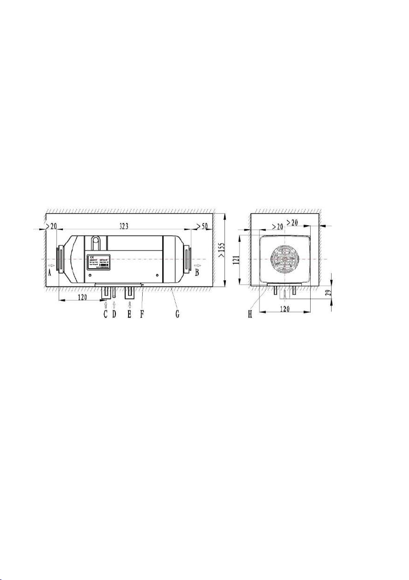
4.2.2 For convenience of heating air flow and installation, maintenance of the main
heater, enough space must be provided for installation. Please refer to the scope of
double dot line for the space for installation, as shown in Fig. 10.
A-Inlet of heating air B-Outlet of heated air C-Inlet of combustion air
D- Fuel inlet E-Exhaust outlet F- Non-interference area
G-Installation surface H-Gasket
Fig. 10
Please make sure that there are not any interference objects in the gap
between the bottom surface of the main heater and the installation surface of the
vehicle (Fig. 8-F).
4.2.3 Good sealing is necessary between the main heater and the installation surface
on the vehicle. A special gasket (as shown in Fig. 10) supplied by the manufacturer must
inserted in between during installation. The installation surface must be smooth and steady
enough. Its parts at the installation bases of the main heater shall have unevenness of less
than 1mm. After drilling installation holes, evenness must be improved according to this
requirement. At installation, please rotate the four M6 nuts, which provided by the
manufacturer should be tighten. The torque for tightening shall be 6Nm+1Nm.
Please refer to Fig. 11 for positions of installation holes.

9
4.2.4 If the sickness of the installation panel<1.5mm a mounting plate may need.
Between mounting plate and the car body must also be sealed (use glass glue(Fig.12).
Attention: For re-installation of the heater ,
a new gasket must be used to replace the old one.
4.2.5Direction for installation of the heater is shown in Fig. 13. Attention must be
paid to that the inclination angle shall
not exceed the limit, or normal
operation will be affected.
4.2.6 After installation of the main
heater, please check and make sure
that there is not any contact or
friction between the blade wheel of
fan and other nearby parts to avoid
unsmooth operation
4.3 Installation of Air Heating System
4.3.1The independent outer circulation or inner circulation mode of heater can be
recommended. If the air heating system of the heater have to be connected with the
air duct of the vehicle, in order to ensure the air duct unobstructed the connection way
should be analyzed by the professionals.
4.3.2 When an external heating air pipe is attached to the heater, the pipe diameter
Fig 12
Fig 11
Fig.13
10
shall not be smaller than 60mm. Its material shall be capable to resist temperature of
130℃.
4.3.3 The maximum pressure drop between the air inlet side and air outlet side of the
air heating system shall not be greater than 0.15kPa.
4.3.4 The hot air from the heating system shall not erupt onto such parts that are
unable to resist heat. In case of passenger vehicles, measures shall be taken to avoid
blocking of the hot air vent by passengers. A self-provided protective net can be
installed if necessary.
4.3.5 For heater working in external circulation mode, the position of air inlet port
shall be proper to guaranteed that under normal operation no splash of water can enter.
No water can be sucked into the heater and no exhaust from the engine can be sucked
in.
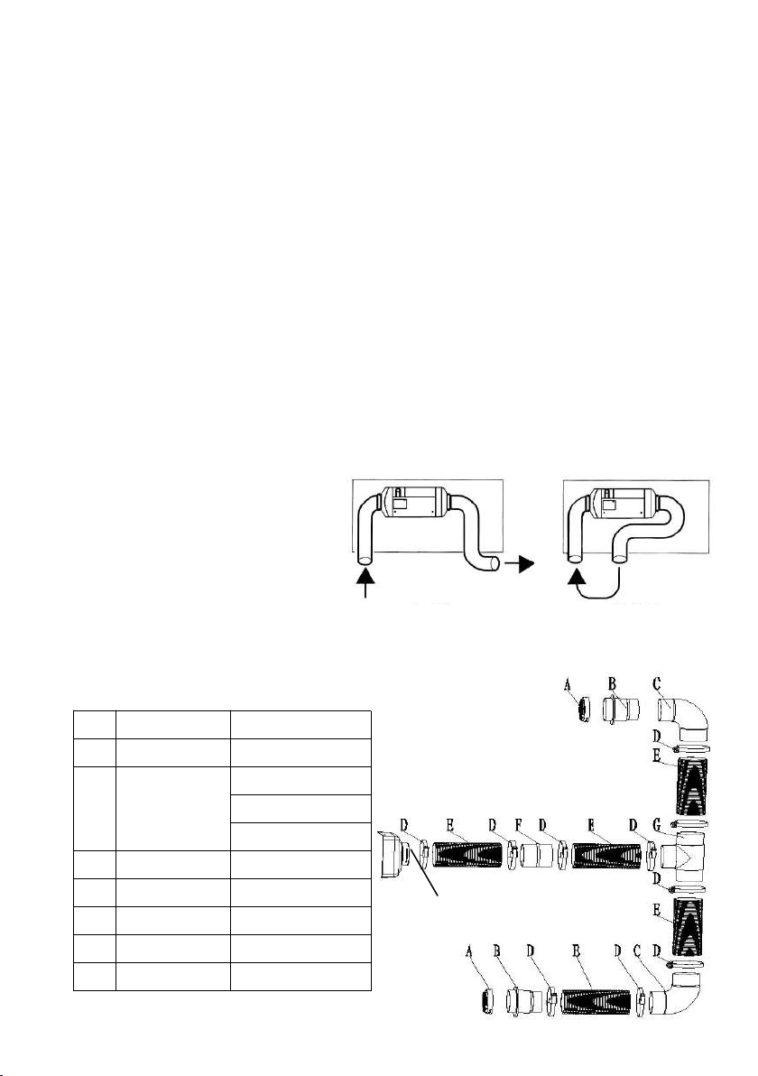
4.3.6 For heater working in internal circulation, measures shall be taken to avoid
re-entering of the supplied hot air into the air inlet port (as shown in Fig. 14). If no air inlet
pipe is attached in this mode, an air inlet hood with grids (Fig3. 4-6) must be installed at
the air inlet port of the main heater. The inlet air shall be drawn from the cold area of the
compartment, such as under the seats or berths.
4.3.7 The optional air duct fittings
Users can choose the air duct fittings according to the situation. Please refer to
Fig.15.
No
Name
Specification
A
Grill
φ90
B
Diameter
changes
joint
φ60
φ90/60
φ56/60
C
Elbow
φ60/90。
D
Clamp
φ50~70
E
Ducting
φ60/φ64
F
Connector
φ60-φ60
G
Reducing T
φ60
a) Correct b) Wrong
Fig. 15
Warm air outlet
Table 3
Fig 14
11
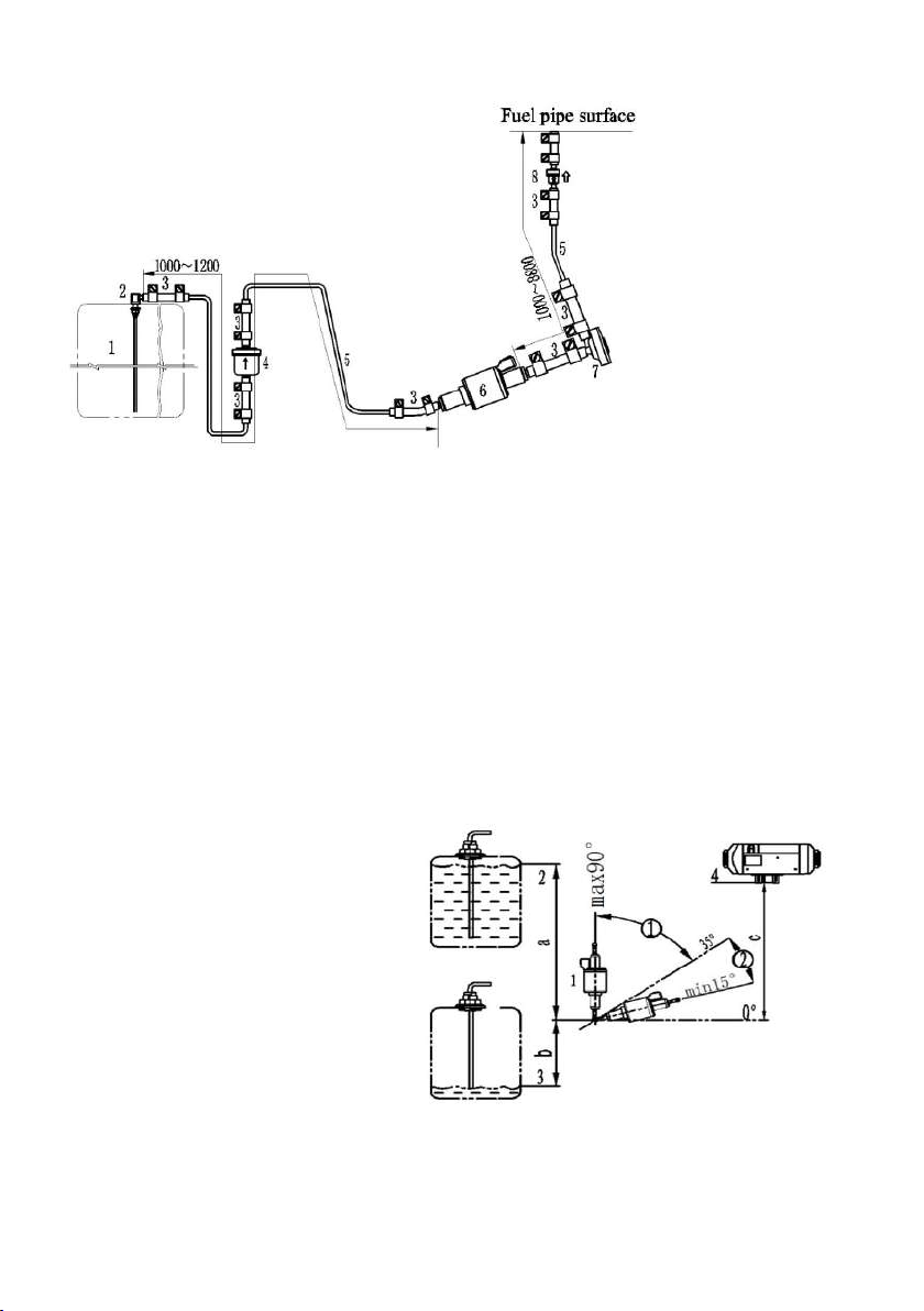
4.4 Installation of Fuel Supply System
The fuel supply system for the heater
is as shown in Fig. 16.
4.4.1 The fuel pump shall be fixed in automobile with a fuel pump clamp with
protective rubber cover. The outlet of the fuel pump shall tilt upwards. The tilt angle
can be selected from the range of 15°~ 35°(as shown in Fig. 17). When conditions
permit, the fuel pipe between the fuel pump and the heater shall go up gradually.
4.4.2 Damper installation should be according to the practical situation. If the packing
list doesn’t include the damper then it is should not be used temporarily.
4.4.3 Difference in elevation between the level of fuel and the fuel pump as well as
the difference in elevation between the fuel pump and the fuel inlet of the heater can
produce pressure (or suction) in the fuel pipeline(See Fig.17).So, these dimensions
shall conform to the requirements as follows:
a≤3m b≤0.5m (Avoid of negative pressure may be produced in sealed fuel tank.
In such case, b≤0.15m) c≤2m.
Note:
1.Please check the vent on the fuel tank when doing installation.
2.Fuel pipe after clipping(must use blade, Scissors or pliers are forbidden)
should ensure not affect fuel flow amount.
Fig.16
1-Fuel pump
2-Max.fuel level
3-Min.fuel level
4-Fuel inlet level
①Allowable installation angle
②Optimum installation angle
1-Fuel tank
2-Fuel extractor
3-Fuel pipe connector
4-Filter
5-Fuel pipe
6-Fuel pump
7-Damper
8- Non-return value
Fig.17
12
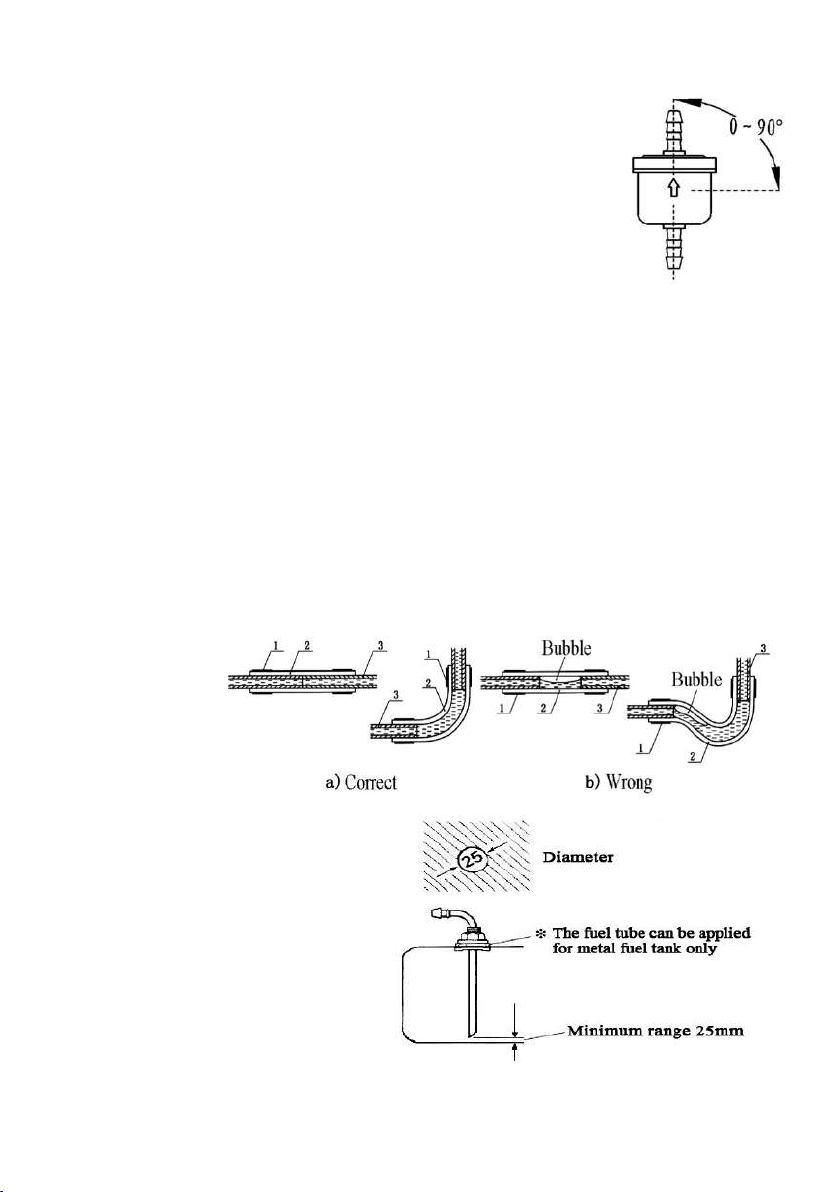
4.4.4 Installation of Fuel Filter
A fuel filter shall be installed before the fuel inlet port.
Please make sure that the fuel flow is correctly followed.
Its position shall be in conformity with Fig. 18.
Fuel filter should be changed after 2 years, fuel pipe joints
and clamps should also be changed.
4.4.5 Installation of Fuel Pipe
4.4.5.1 Only the flexible nylon pipe, which has good
light-resistance and thermal stability, supplied with the heater can
be used as the fuel pipe. The inner diameter of the pipe is Φ2mm.
4.4.5.2 The place for installation of fuel pipe shall be resistant against flying stones
and shall be away from any heat emitting parts of the vehicle. Protective device can
be installed if necessary.
4.4.5.3 The fuel pipe from the fuel pump to the main heater shall be in any directions
other than downward direction. The fuel pipe shall be tied in some proper location to
make it fixed. The distance between two ties shall be less than 50cm.
4.4.5.4 The fuel pipe fittings supplied with the heater shall be used for connections
between fuel pipe and fuel pump, fuel pipe and heater, fuel pipe and sucking pipe of
fuel tank and fuel pipe and reducing T. The fuel pipe shall ties with fuel pipe clamps.
Bubbles shall be eliminated from the connecting places (Fig. 19).
4.4.6 Installation of Fuel Sucking Device (Fig.20)
4.4.6.1When fuel is sucked from the
vehicle fuel tank or from an independent
fuel tank, a sucking pipe shall be used.
Attention shall be paid to that the openings
on the fuel tank (or tank cover) for
installation shall be size φ25±0.2,
with trimmed brim and with good
evenness around the opening. Good
sealing is necessary for the base of the
fuel sucking pipe. The bottom end of the fuel sucking pipe shall be 30mm-40mm
from the bottom of fuel tank to suck enough fuel and at the same time to avoid
Fig.18
1-Fuel pipe clamp;
2-Fuel pipe fitting;
3-Fuel pipe
Fig.19
Fig.20
13
From fuel tank
Reducing T
To fuel filter,
vehicle
Fuel pump
and engine
To fuel pump of heater
sucking in impurities sediment on the bottom of fuel tank.
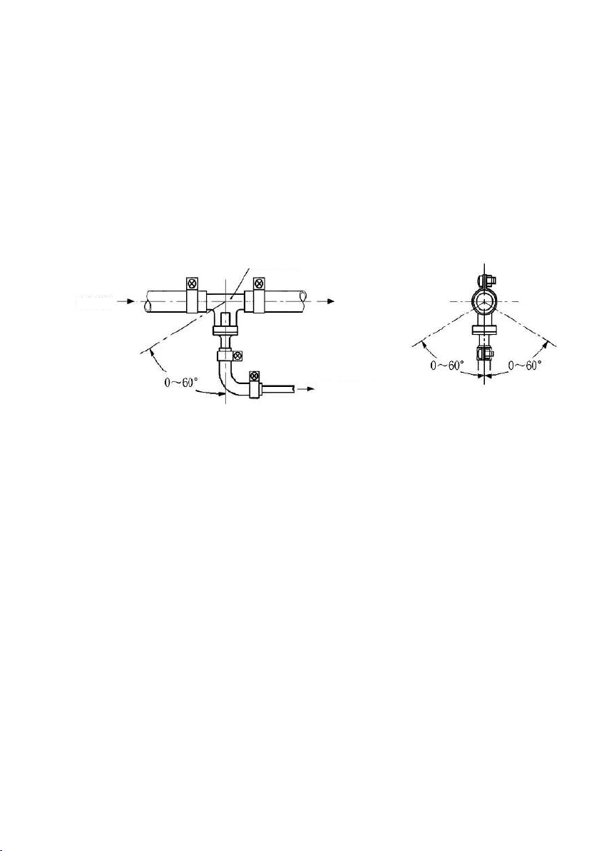
4.4.6.2 If fuel is sucked from the fuel pipe to the engine, the fuel pipe from
the fuel tank to the fuel filter shall be disconnected and re-connected with the thicker
pipes of the reducing T and the thinner pipe of the reducing T shall connect the fuel
pump of the heater via oil pipe fitting and fuel pipe. Must ensure fuel extraction
without any pressure and extract the fuel smoothly when the car is stopping. The
angle for installation must in conformity with Fig. 21, or normal work of the heater
will be affected.
After installation, the vehicle engine shall be started and then turned off after one
minute’s work to eliminate air trapped in the fuel sucking pipe.
4.5 Installation of Electrical System
4.5.1 The wiring diagram for the heater is shown in Fig. 22. The wires of the main
heater for connection to outside circuits have been made into wire bundles. They can
be laid according to the positions of various components and shall be fixed in some
proper locations. The distance between two fixing points shall not exceed 30cm.
Attention: Any exposed wire bundle out of the vehicle body or out of the wiring
groove must be protected by corrugated pipe.
4.5.2 Connection of the main wire bundle with the heater: Use a blunt tool to pry the
places marked “ ○
Q”of Fig.4 gently to remove the junction box cover (Fig. 4-1).
Connect the 18-wire connector X6 of the wire bundle to the controller socket. The
wire bundle can come out from either the right
side or the left side of the heater. Then replace the junction box cover. Make sure to
have good sealing between the junction box cover and upper cover and between the
junction cover box and the wire bundle sealing mat to avoid any thermal malfunction
due to leak of air from the hood-shape case.
4.5.3 Straighten the fuel pump leads (two 0.6mm2black wires and not distinguish
positive and negative) with their protective pipes, which is made a coil inside the
combustion supporting air inlet port , and put them through the opening on the wall of
the air inlet pipe. Connect the insert of fuel pump connector with fuel pump(Insert the
right position).Cutting fuel pump leads is forbidden.
4.5.4 Use four self-tapping screws to fix the control switch in a position for
convenient operation and the arrangement shall make easy observation on the
Fig.21

14

15
indicator on the case, so as to identify the working conditions (operation/stop) of the
heater easily. The plugs on the leads from the control switch shall be connected to the
main wire bundle and make self-locking mechanism. Note to remove the knob firstly,
then install the knob after fixing the screw.
4.5.5 Insert sheet fuse into fuse holder F and replace the upper cover tightly. Use
screws to fix it in a proper location in the vehicle.
4.5.6 Connect the 2.5mm2red wire and the 2.5 brown wire in the wire bundle to the
hole terminals with springs and therefore connect to the “+” and “-” terminals of the
vehicle battery.
The length and cross-sectional area of the power line shall ensure that the allowable
voltage drop is not greater than 0.5V and 1.0V when the voltage is 12V and 24V. It is
recommended to configure the power cord according to the following table.
4.6 Installation of combustion supporting air sucking pipe and exhaust discharge pipe
4.6.1 The combustion supporting air must be sucked in from external fresh
air outside the vehicle. The exhaust from combustion must be discharged into the air
through exhaust pipe. Measures must be taken to avoid the exhaust from re-entering
the vehicle.
The pipes go through the outer wall or holes on the bottom of vehicle.Measures
must be taken to prevent entering of splash water. The pipes must be protected and
can resist shock permanently.
4.6.2 Only the air inlet pipe and exhaust pipe provided with the heater can be used. The
air inlet pipe is a corrugated pipe made of a aluminum pipe that it’s surface is covered by
plastic and paper;The exhaust pipe is corrugated stainless steel pipe. Please identify air
inlet pipe and exhaust pipe and do not make mistake at installation. To connect them with
the heater, please use the supplied clamps to fix them tightly
on the combustion. The protective hood on the vents of the
air inlet pipe and exhaust pipe must be kept in good condition.
Do not damage them or remove them.
In order to meet the dust environment, an
optional air filter is a good choice(Fig.23).
A length of air filter can be cut in order to
meet different thickness of air inlet pipes.
Plus cable + minus cable
cross section
<8m
2.5mm2
8~12m
4mm2
12~16m
6mm2
Fig.23
16
a) Correct
4.6.3 Both the air inlet pipe and exhaust
pipe shall come outwards and
downwards from the heater (Fig. 24),
otherwise a Φ4mm hole shall be
prepared at the bottom of the pipe for
discharge of condensation water.
If the pipe need curve, the radius cannot
be smaller than 50mm.Also, the sum of
all curve angles for each pipe shall not
exceed 270°.
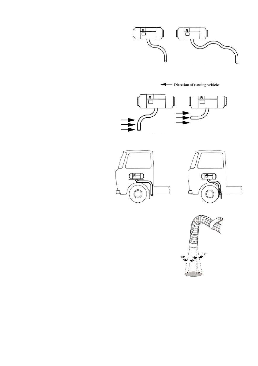
4.6.4 The openings of the pipes
shall not be opposite to the direction
of the running vehicle. (Fig. 25)
4.6.5 Arrangement of the
pipes shall protect the pipe
openings from blocking by
slurry, rain and snow or
other dirt. (Fig. 26)
4.6.6 When the heat is working, the exhaust pipe is at high
temperature. In installation, make sure to install it in far
distance from plastic parts or other objects with poor
thermal resistance of the vehicle body. The exhaust
pipe shall be properly fixed. The exhaust vent shall
be downwards, perpendicular to road surface with an
angle of 90°±10°. To ensure such an angle, the fixing
clamp for the exhaust pipe shall be within 150mm from the pipe end. (Fig. 27)
Warning: Violation against the above requirements may cause fire.
Any consequences caused by not installing according our requirement we don’t afford any
responsibility.
4.6.7 If the section of the exhaust pipe inside the vehicle may be touched by passenger,
a protective cover has to be installed to prevent human contact and scald.
Fig.27
a) Correct b) Wrong
Fig.26
Fig.24
b) Wrong
Fig.25
b) Wrong
a) Correct
Direction of running vehicle

17
5 Methods of Operation
5.1 The heater control with three ways.
(1) Use the control switch(normal configuration).
(2) Use LCD control switch(optional choice).
(3) Use GSM mobile phone controller(optional choice).
5.2 Use the control switch
5.2.1Power on
Push air conditioner(constant temperature)button or heating(constant power) button,
then the indicator light of air conditioner(constant temperature)or heating(constant
power) flash 0.3S, then lit, said controller has started work, enter the corresponding
working mode. The heater comes to the start stage. The controller will run heating
program according to the temperature control target set by the control knob. In the
start stage, the time delay from switch-on to fuel supply to the fuel pump is 65
seconds.
5.2.2 Power control
After the combustor is ignited, if you want to regulate the heating temperature or
the heater power, you can turn the control knob according to the arc mark around the
control switch.
5.2.2.1 Air conditioner(constant temperature) mode
The air conditioner(constant temperature) mode indicating light is illuminated
after pressing air conditioner (constant temperature)button. If you want to adjust the
heating temperature(adjustable continuously from 5℃to 35℃),press the curve sign on
the control switch and turn the control knob.
5.2.2.2 Constant power mode
The heating(constant power) mode indicating light is illuminated after pressing
heating (constant power)button. If you want to adjust the heating power(adjustable
continuously between 1KW and 2KW), press the curve sign on the control switch and
turn the control knob.
5.2.3 Ventilation mode
You can only enter the ventilation mode when you press the ventilation mode key
to start the heater. The ventilation indicating light turns green after pressing
ventilation button. Heater can only circulating air without any heating. The wind
capacity can be continuously regulated with the control knob.
5.2.4 Shutdown
If you want to turn off the heater manually, press the button which is lighting on then
work indicator goes out. If the fuel pump is at work before the heater is turned off, the
pump will shut down immediately. But the fan will continue to run for 180 seconds.

18
5.2.5 Use any other way shut off the heater (cut off the power) directly is not
allowable.
6 Treatment of Usual Troubles
6.1 During use, the heater may become unable to start normally or die out after start.
Such troubles may lead to locking state. In such case, you can press the button which is
lighting on then work indicator goes out. Turn off the heater and keep it in such state for
at least 5 seconds. Then, restart the heater.
6.2 Circuit troubles may be caused by different reasons, such as corrosion of
connectors, poor contact of connectors, wrong connection of wires, corrosion of wires
or fuse, corrosion and looseness of battery poles, etc. Users need to check and prevent
such troubles and offer good maintenance.
6.3 The reasons for the troubles to the heater can be indicated by the green LED on
the control switch (see Section 3.3.3 for details). When the following troubles occur,
users can take measures to solve:
(a)Failure to turn on the heater and the indicator light is not illuminating, the
reason is open circuit of fuse or wrong connection of wires.
(b)The heater runs idly and no start process occurs after the heater is powered on,
this indicates that the temperature of air inlet (or the ambient temperature around the
external temperature sensor) is higher than the set heating temperature, or called hot
start. In such case, you need to turn the control switch knob clockwise to have a
higher set temperature.
(c)When the LED flashes once, troubleshooting can be solved by the methods list in
table 4.
This manual suits for next models
1


