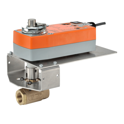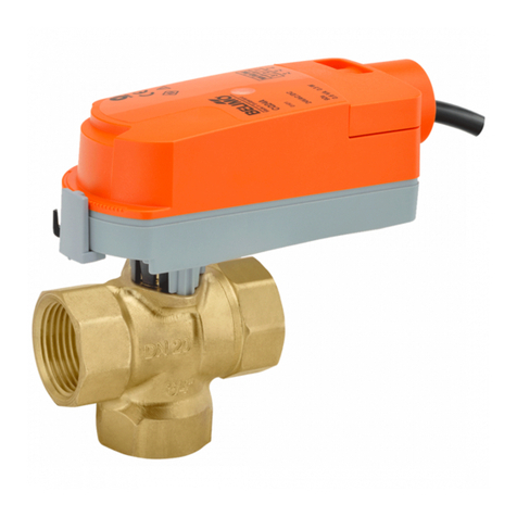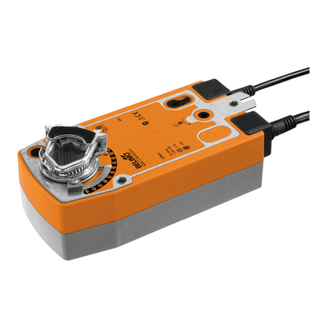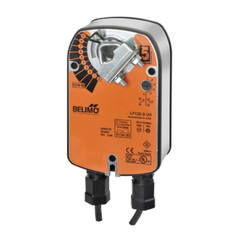
102
V8.3 04.2015•Subject to modication
UL marked actuators is optional, please contact your local Sales Representative for details.
Mode of operation The actuator is controlled with a standard modulating signal of DC (0)2...10V and moves to
the position dened by the control signal. The measuring voltage U serves for the electrical
display of the damper position 0...100% and as slave control signal for other actuators.
Simple direct mounting Straightforward direct mounting on the ball valve with only one screw. The assembly tool
is integrated in the plug-on position indicator. The mounting position in relation to the tting
can be selected in 90° steps.
Manual override Manual override with push-button possible (the gear is disengaged for as long as the button
is pressed or remains locked).
Adjustable angle of rotation Adjustable angle of rotation with mechanical end stops.
High functional reliability The actuator is overload-proof, requires no limit switches and automatically stops when the
end stop is reached.
Position feedback U5 Operation of the ball valve is optimised by a limiting ring. This ring reduces the angle of
rotation from 95° to 90°, i.e. U5 will deviate from Y by approximately 0.3V when the valve is
closed.
Home position When the supply voltage is switched on for the rst time, i.e. at commissioning or after
pressing the «gear disengagement» switch, the actuator moves to the home position.
Factory setting: Y2 (counter-clockwise rotation)
Rotary actuator Rotary valve
Y2
A – AB = 0%
Y1
A – AB = 100%
The actuator then moves into the position dened by the control signal.
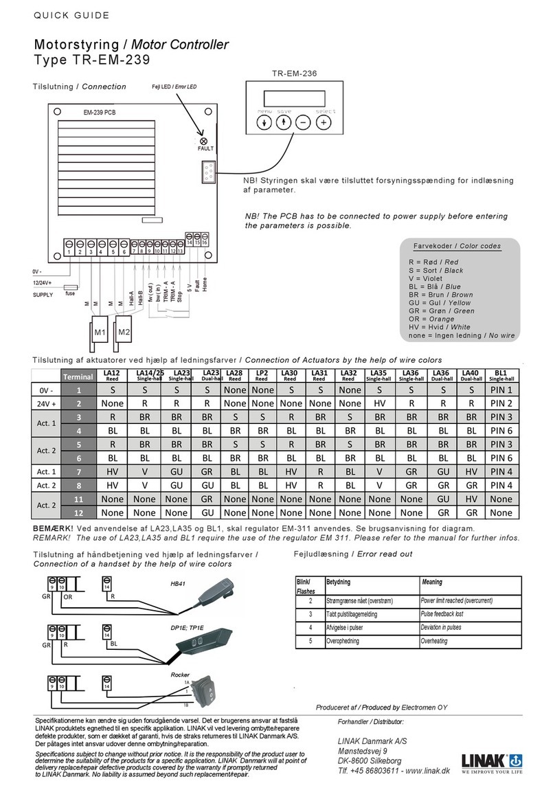
Wiring diagram Standard connection Override control (frost protection circuit)
Y
1 32
DC 0 ... 10 V
– +
5
UDC 2 ... 10 V Y
1 32
DC 0 ... 10 V
– +
T
~
cd
5
Note
• Connect via safety isolation transformer.
• Parellel connection of others actuators possible.
Note the performance data.
• Direction of rotation switch is covered.
Factory setting: Direction of rotation Y2
Control of controller
Measuring voltage
for reset signal
c d Rotary actuator Rotary valve
Y1 A –AB = 100%
Y2 A – AB = 0%
Modulating operation
Control of controller
Direction of rotation
Y1
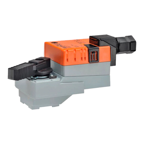
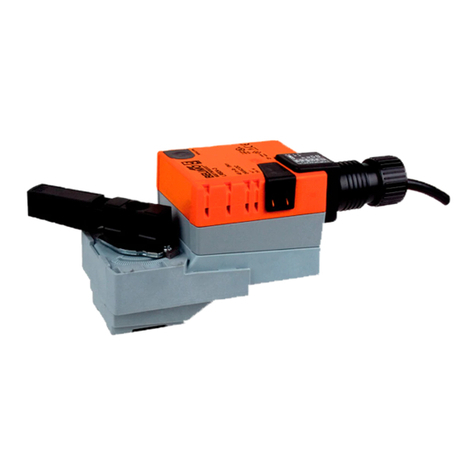
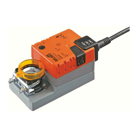
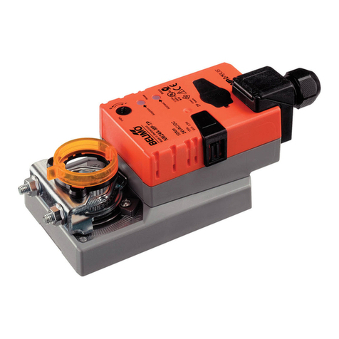
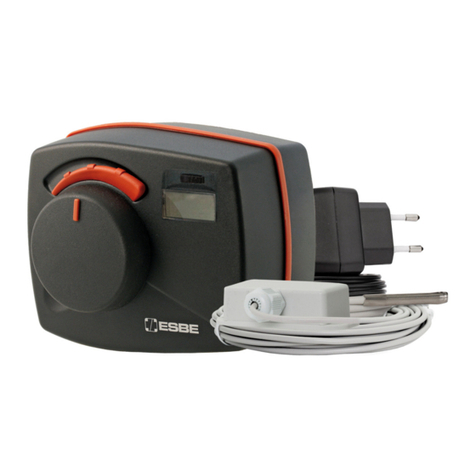
Modulating rotary actuator, AC/DC 24V, 4Nm, running time 9s
LRQ24A-SR
Product features
Accessories
Electrical installation
Description Type
Electrical accessories Auxiliary switch, add-on, 1 x SPDT S1A
Auxiliary switch, add-on, 2 x SPDT S2A
Feedback potentiometer 140 Ohm, add-on P140A
Feedback potentiometer 200 Ohm, add-on P200A
Feedback potentiometer 500 Ohm, add-on P500A
Feedback potentiometer 1 kOhm, add-on P1000A
Feedback potentiometer 2.8 kOhm, add-on P2800A
Feedback potentiometer 5 kOhm, add-on P5000A
Feedback potentiometer 10 kOhm, add-on P10000A
DC (0)2...10V
DC (0)2...10V
Safety notes
• The device may only be opened at the manufacturer‘s site. It does not contain any parts
that can be replaced or repaired by the user.
• The cable must not be removed from the device.
• Self adaptation is necessary when the system is commissioned and after each adjustment
of the angle (press the adaptation push-button)
• The device contains electrical and electronic components and is not allowed to be
disposed of as household refuse. All locally valid regulations and requirements must be
observed.


