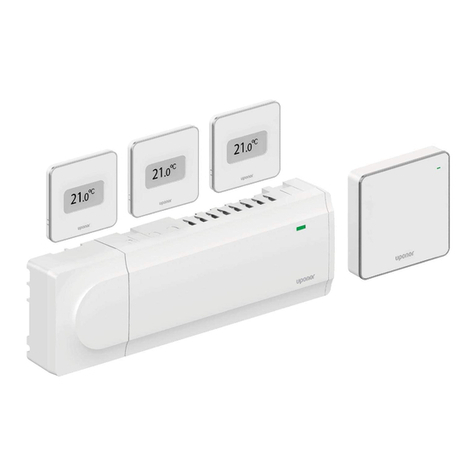
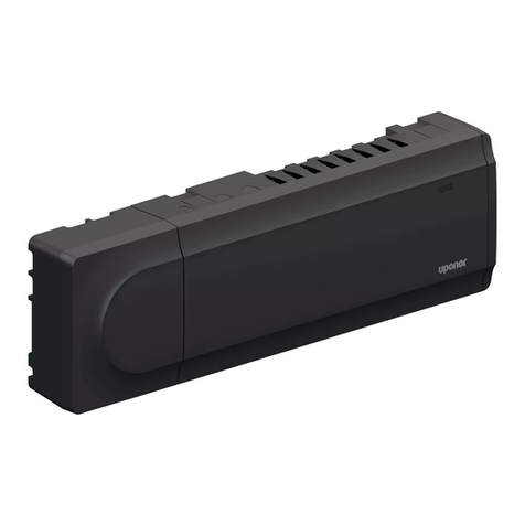
Uponor Smatrix Base PULSE User manual

Smatrix Pulse
Installation and Operation Manual

Uponor Smatrix Pulse Installation and Operation Manual
is published by
Uponor Inc.
5925 148th Street West
Apple Valley, MN 55124 USA
T800.321.4739
F952.891.2008
Uponor Ltd.
6510 Kennedy Road
Mississauga, ON L5T 2X4 CANADA
T888.594.7726
F800.638.9517
uponor.com
© 2022 Uponor
All rights reserved.
First edition
First printing October 2022
Printed in the United States of America

uponor.com l 1
Table of Contents
Foreword ...................................................................................2
Chapter 1: Copyright and Disclaimer...................................3
Compliance .....................................................................................................4
Chapter 2: Safety Instructions ..............................................5
Chapter 3: System Description ............................................. 7
System Overview..........................................................................................7
Hardware Overview ....................................................................................7
Hardware Descriptions.............................................................................8
Chapter 4: System Functionality......................................... 11
Standard Functionality.............................................................................11
Smart Home Connectivity......................................................................11
Heating/Cooling Offset.......................................................................... 13
Room Bypass................................................................................................. 13
Chapter 5: Hardware Installation....................................... 15
Installation Procedure.............................................................................15
A380265C/A380265A Controllers...................................................16
A3801263 Expansion Module (M-262).......................................... 17
Communication Module (R-208)................................................... 17
Antenna (A-265) ........................................................................................18
A3801263 Relay Module (M-263).....................................................18
Thermostats...................................................................................................19
Chapter 6: Wiring....................................................................21
Controller ......................................................................................................... 21
Output Relays...............................................................................................22
Relay Module................................................................................................23
Thermostats..................................................................................................25
Chapter 7: Connecting Wireless Devices .......................... 27
Chapter 8: Clearing Setup Information or Resetting
Devices .....................................................................................31
Chapter 9: System Operation..............................................33
Chapter 10: Maintenance .....................................................39
Chapter 11: System Connectivity ........................................ 41
Chapter 12: Troubleshooting................................................43
Chapter 13: Technical Data.................................................. 51

2 l Smatrix Pulse | Installation and Operation Manual
Foreword
Uponor is dedicated to partnering with professionals to
create better human environments. As the leading North
American manufacturer of Engel-method crosslinked
polyethylene (PEX-a) piping and provider of PP-RCT
piping solutions, Uponor is dedicated to offering products,
systems, services, support, and solutions to design, install,
and operate high-performing piping systems.
As part of this support, Uponor publishes the Smatrix
Pulse Installation and Operation Manual for contractors,
engineers, architects, building officials, building managers,
and other individuals interested in radiant heating and
cooling as well as HVAC systems.
Uponor has made reasonable efforts to collect, prepare,
and provide quality information and material in this
manual. However, system enhancements may result in
modification of features or specifications without notice.
Note that Uponor is not liable for installation practices
that deviate from this manual or are not acceptable
practices within the mechanical trades, codes, or
standards of practices. If there are differences between
Uponor recommendations and local code, always follow
the more-restrictive criteria. For example, where Uponor’s
recommendations are more restrictive than the local
code, follow the Uponor recommendations to ensure
the product performs as expected and remains covered
under warranty. For warranty information, visit uponor.com
and search "warranty".
It is the installer’s responsibility to ensure the product,
design, and intended installation are acceptable to the
local authority having jurisdiction (AHJ). Please direct any
questions regarding the suitability of an application to
Uponor Technical Services at 888.594.7726 or
Warning!
California Proposition 65 Warning: This product
contains chemicals known to the state of
California to cause cancer and birth defects or
other reproductive harm. For more information,
visit P65Warnings.ca.gov.

uponor.com l 3
Chapter 1:
Copyright and Disclaimer
Uponor has prepared this installation and operation
manual and all the content included solely for information
purposes. The contents of the manual (including
graphics, logos, icons, text, and images) are copyrighted
and protected by worldwide copyright laws and treaty
provisions. The user agrees to comply with all copyright
laws worldwide. Modification or use of any of the contents
of the manual for any other purpose is a violation of
Uponor’s copyright, trademark, and other proprietary
rights. The presumption for the manual is that the safety
measures have been fully complied with and, further, that
the Uponor Smatrix Pulse control system, including any
components that are part of such system, covered by the
manual:
• Is selected, planned, and installed and put into operation
by a trained, licensed, and experienced professional
in compliance with current (at the time of installation)
installation instructions provided by Uponor as well as in
compliance with all applicable building and plumbing
codes and other requirements and guidelines.
• Has not been (temporarily or continuously) exposed to
temperatures, pressure and/or voltages that exceed
the limits printed on the products or stated in any
instructions supplied by Uponor.
• Remain in its originally installed location and is not
repaired, replaced, or interfered with, without prior written
consent of Uponor.
• Is connected to potable-water supplies or compatible
plumbing, heating, and/or cooling products approved or
specified by Uponor.
• Is not connected to or used with non-Uponor products,
parts, or components, except for those approved or
specified by Uponor; and
• Does not show evidence of tampering, mishandling,
insufficient maintenance, improper storage, neglect, or
accidental damage before installation and being put
into operation.
While Uponor has made efforts to ensure that the manual
is accurate, Uponor does not guarantee or warrant the
accuracy of the information contained herein. Uponor
reserves the right to modify the specifications and
features described herein or discontinue manufacture of
the Uponor Smatrix Pulse products described at any time
without prior notice or obligation. The manual is provided
“as is” without warranties of any kind, either expressed or
implied. The Information should be independently verified
before using it in any manner.
To the fullest extent permissible, Uponor disclaims all
warranties, expressed or implied, including, but not limited
to, the implied warranties of merchantability, fitness for
particular purpose, and non-infringement.
This disclaimer applies to, but is not limited to, the
accuracy, reliability, or correctness of the manual.
Under no circumstances shall Uponor be liable for any
indirect, special, incidental, or consequential damages
or loss that result from the use of or the inability to use
the materials or information in the manual, or any claim
attributable to errors, omission, or other inaccuracies
in the manual, even if Uponor has been advised of the
possibility of such damages. Uponor’s total cumulative
liability, if any, will not exceed the amount the user actually
paid for the Uponor Smatrix Pulse wireless control system.
This disclaimer and any provisions in the manual do not
limit any statutory rights of consumers.
4 l Smatrix Pulse | Installation and Operation Manual
Compliance
This device complies with Part 15 of the FCC Rules.
Operation is subject to the following two conditions:
1. This device may not cause harmful interference, and
2. This device must accept any interference received,
including interference that may cause undesired
operation.
Note: The grantee is not responsible for any changes
or modifications not expressly approved by the party
responsible for compliance. Such modifications could
void the user’s authority to operate the equipment.
Note: This equipment has been tested and found to
comply with the limits for a Class B digital device,
pursuant to Part 15 of the FCC Rules. These limits are
designed to provide reasonable protection against
harmful interference in a residential installation. This
equipment generates, uses, and can radiate radio
frequency energy and, if not installed and used in
accordance with the instructions, may cause harmful
interference to radio communications. However, there
is no guarantee that interference will not occur in a
particular installation. If this equipment does cause
harmful interference to radio or television reception, which
can be determined by turning the equipment off and on,
the user is encouraged to try to correct the interference by
one or more of the following measures:
• Reorient or relocate the receiving antenna.
• Increase the separation between the equipment and
receiver.
• Connect the equipment into an outlet on a circuit
different from that to which the receiver is connected.
• Consult the dealer or an experienced radio/TV technician
for help.
This device contains license-exempt transmitter(s)/
receiver(s) that comply with Innovation, Science and
Economic Development Canada’s license-exempt RSS(s).
Operation is subject to the following two conditions:
1. This device may not cause interference.
2. This device must accept any interference, including
interference that may cause undesired operation of the
device.
L’émetteur/récepteur exempt de licence contenu dans
le présent appareil est conforme aux CNR d’Innovation,
Sciences et Développement économique Canada
applicables aux appareils radio exempts de licence.
L’exploitation est autorisée aux deux conditions suivantes :
1. L’appareil ne doit pas produire de brouillage;
2. L’appareil doit accepter tout brouillage radioélectrique
subi, même si le brouillage est susceptible d’en
compromettre le fonctionnement.
FCC ID: V9MSM4NA0 and V9MSM4NA1
IC: 7664A-SM4NA0 and 7664A-SM4NA1

uponor.com l 5
Chapter 2:
Safety Instructions
This installation and operation manual describes how to
install and properly setup the components of the Uponor
Smatrix Pulse system.
Refer to the following important safety instructions before,
during, and after installation of the Smatrix Pulse system.
Symbols
The following symbols are used in Uponor documentation
to show special precautions when installing and operating
any Uponor equipment.
Warning!
Risk of injury or component damage. Ignoring
warnings can cause personal injury or damage to
system components.
Caution!
Risk of equipment malfunction. Ignoring cautions
can cause system malfunctions.
Note
Important information to the section in the
manual.
Safety Measures
Conform to the following measures when installing and
operating any Uponor equipment.
• Read and follow the instructions in the installation and
operation manual.
• Installation must be performed by a trained, licensed,
and experienced professional in accordance with local
regulations.
• It is prohibited to make changes or modifications not
specified in this manual.
• All power supplies must be switched off before starting
any wiring work.
• Do not use water to clean Uponor components.
• Do not expose the Uponor components to flammable
vapors or gases.
Uponor cannot accept any responsibility for damage
or breakdown that can result from ignoring these
instructions.
Power
Warning!
The Uponor system uses 115V 60 Hz AC power. In
case of emergency, immediately disconnect the
power.
Technical Constraints
Caution!
To avoid interference, keep installation/data
cables away from power cables of more than 50V.
Limitations for Radio Transmissions
Wireless Uponor products use radio transmission for
communication. The frequency used is reserved for similar
applications, and the chances of interference from other
radio sources are very low.
However, in some rare cases, it might not be possible to
establish perfect radio communication. The transmission
range is sufficient for most applications, but each
building has different construction that may affect radio
communication and maximum transmission distance.
If communication difficulties exist, Uponor recommends
relocating the antenna to a more optimal position and
installing Uponor radio sources at least 16" (41 cm) apart
for solving communication problems.
Disposal
At the end of its working life, do not dispose of any Smatrix
Pulse components with other household waste. To prevent
possible harm to the environment or human health
from uncontrolled waste disposal, please separate this
from other types of wastes and recycle it responsibly to
promote the sustainable reuse of material resources. For
proper disposal information, contact local recyclers for
environmentally safe recycling.

6 l Smatrix Pulse | Installation and Operation Manual

uponor.com l 7
Chapter 3:
System Description
Smatrix Pulse is a wireless zoning control system designed
for radiant heating and cooling installations with the
ability to integrate forced-air heating and cooling.
System Overview
The Smatrix Pulse hardware consists of one or multiple
controllers, an optional Communication Module,
thermostats, actuators, and wireless relays. The Controller
manages the operation of the actuators when the
thermostats detect a demand for heating and/or cooling.
System optimization and settings (for up to four
controllers) is completed through the Smatrix Pulse App
(connected via the Communication Module). The system
can function without the Communication Module but will
reduce the level of system functionality.
Different models of thermostats control heating and
cooling operation. Designed for maximum comfort, the
thermostats communicate with the controller by radio
link. It is possible to mix the different types of Smatrix Pulse
thermostats in the same installation.
Wireless relays provide installation flexibility when needing
to control other heating and cooling devices when running
additional wiring is a challenge.
Hardware Overview
The figure below shows the hardware available for the
Uponor Smatrix Pulse system.
Figure 3-1: Smatrix Pulse hardware
Part
Number Description Reference Maximum
per
System
A380265C
Controller (X-265) with
Communication Module
(R-208)
A, F, H 1
A380265A Controller (X-265) with
Antenna (A-265) A, G, H 3
A3800169 Digital Thermostat
(T-169) B48
A3800161 Mini Sensor (T-161) C
A3801262 Expansion Module
(M-262) D 4
A3801263 Relay Module (M-263) E 16*
A3801208 Communication Module,
replacement part F N/A
A3801265 Antenna, replacement
part G N/A
A3850050 Transformer,
replacement part H N/A
A3030522
Two-wire Thermal
Actuator for Uponor
EP Heating Manifolds
I 56A3030523
Two-wire Thermal
Actuator for Uponor
TruFLOW™ Classic and
Jr. Valved Manifolds
A3030524
Two-wire Thermal
Actuator for Uponor
Stainless-steel Manifolds
Table 3-1: Smatrix Pulse hardware
*Limit of four (4) A3801263 Relay Modules (M-263) per Controller

8 l Smatrix Pulse | Installation and Operation Manual
Hardware Descriptions
A3800169 Digital Thermostat
(T-169)
The Digital Thermostat shows the
current room temperature, set
temperature, or relative humidity on
the display. Temperature settings are
adjusted using the buttons on the
side of the thermostat.
Main Features
• Power saving e-paper display (updates every 10
minutes)
• Displays Fahrenheit or Celsius
• Operative sensor for increased comfort
• Calibration of displayed room temperature
• Heating/cooling demand as well as low battery
indication on display
• Displays Uponor logo and software version during power
up sequence
• Setpoint range is 41 – 95°F (5 – 35°C); maximum and
minimum setting may be limited by system settings
• Enhanced room temperature control with use of optional
floor sensor
• Displays optional temperature sensor values if sensors
are connected and relevant functionality is activated
• Switch between Comfort and ECO mode with scheduling
(requires Smatrix Pulse App)
• Adjust ECO setback value
• Relative humidity limit alarm indicated in display
(requires Communication Module)
• Invert display color
• Communication distances up to 98 ft. (30 m) away from
the controller
Included Components
• Digital Thermostat (T-169)
• Wall bracket
• Adhesive tape
• Battery (CR2023 3V)
• Mounting hardware (for wall bracket)
A3800161 Mini Sensor (T-161)
The Mini Sensor is a small, simple
thermostat with no display or
buttons. Use this in rooms for discreet
temperature monitoring without
the need for local temperature
adjustment.
Main Features
• Operative sensor for increased comfort
• Adjust setpoint temperature via the Smatrix Pulse App
(requires Communication Module)
• Setpoint range is 41 – 95°F (5 – 35°C); maximum and
minimum setting may be limited by system settings
• Optional floor temperature sensor (connected to the
thermostat); floor temperature settings (maximum/
minimum) only available using the Smatrix Pulse App
(requires Communication Module); otherwise, uses
system defaults
• Relative humidity limit indicated in Smatrix Pulse App
(requires Communication Module)
• Communication distances up to 98 ft. (30 m) away from
the controller
Included Components
• Mini Sensor (T-161)
• Wall bracket
• Adhesive tape
• Battery (CR2023 3V)
• Mounting hardware (for wall bracket)
Figure 3-2:
A3800169 Digital
Thermostat
(T-169)
Figure 3-3:
A3800161 Mini
Sensor (T-161)

uponor.com l 9
A380265C Controller (X-265) with
Communication Module (R-208)
Warning!
Per Table 3-1, use Uponor 24V actuators to ensure
compatibility with the controller.
The Controller operates the actuators, which, in turn,
affect the flow of the supply water to change the
indoor temperature using information transmitted from
registered thermostats and system parameters.
The Controller, which is typically located near the system
manifolds, can operate up to six (6) thermostats and eight
(8) actuators.
Main Features
• Integrated Dynamic Energy Management functions
• Autobalancing (default)
• Comfort setting, room bypass, supply temperature
monitoring (requires Smatrix Pulse App and
Communication Module)
• Electronic control of 24V actuators
• Connects up to eight (8) actuators
• Two-way communication with up to six (6) thermostats
• Heating/cooling outputs, and/or Comfort/ECO mode
switched by dry contact or Smatrix Pulse App (requires
Communication Module)
• Separate relays for control of pump and boiler (other
control functionality available via Smatrix Pulse App)
• Valve and pump exercise
• Relative humidity control (requires Smatrix Pulse App)
• Control of combined underfloor heating/cooling and
ceiling cooling or fan coils (requires Smatrix Pulse App)
• Lower indoor temperature in heating mode or increase
indoor temperature in cooling mode with ECO mode; ECO
mode activates in all rooms at once using a dry contact
or Smatrix Pulse App (requires Communication Module)
• 115V plug-in power cord (42")
Options
• App connectivity via Communication Module (remote
connection requires connection to Uponor Cloud services)
• Increase controller functionality by adding an Expansion
Module for up to six (6) additional thermostats and up to
six (6) additional actuators
• Connect up to four controllers into one system
(requires Smatrix Pulse App)
• Modular placement (detachable Transformer)
• Free placement and orientation when installing Controller
(except Communication Module)
Included Components
• A380265C Controller (X-265) with Communication
Module (R-208)
• Power supply/Transformer (part number A3850050)
• DIN rail
• Mounting hardware
• End cap
A3801262 Expansion Module (M-262)
The Expansion Module will increase the Controller
capacity with six (6) additional thermostats along with
six (6) more actuators. The Expansion Module operates
the actuators, which, in turn, affect the flow of the
supply water to change the indoor temperature using
information transmitted from registered thermostats and
system parameters.
Main Features
• Electronic control of 24V actuators
• Connects up to six (6) additional actuators
• Two-way communication with up to six (6) additional
thermostats
• Plug-in connection with the Controller
• No additional power wiring needed
Included Components
• A3801262 Expansion Module (M-262)
Figure 3-4: A380265C Controller
(X-265) with Communication
Module (R-208)
Figure 3-5: A3801262 Expansion Module (M-262)

10 l Smatrix Pulse | Installation and Operation Manual
A380265A Controller (X-265)
with Antenna (A-265)
Warning!
Per Table 3-1, use Uponor 24V actuators to ensure
compatibility with the Controller.
The Controller operates the actuators, which, in turn,
affect the flow of the supply water to change the
indoor temperature using information transmitted from
registered thermostats and system parameters.
The Controller, which is typically located near the system
manifolds, operates up to six (6) thermostats and eight
(8) actuators.
Note
If using remote access to view and adjust
room temperatures along with other smart
home settings, the system must include one
Communication Module.
Main Features
• Integrated Dynamic Energy Management functions, such
as autobalancing (on by default)
• Electronic control of 24V actuators
• Connects up to eight (8) actuators
• Two-way communication with up to six (6) thermostats
• Heating outputs for Boiler and Pump operation
• General purpose input (GPI) for heating/cooling switch
over
• Valve and pump exercise
• Control of combined underfloor heating and cooling
• ECO mode provides lower indoor temperature in heating
mode and increased indoor temperature in cooling
mode; activated in all rooms at once using a dry contact
• Communication distances up to 98 ft. (30 m) away from
the controller when used as a sub-Controller
• 115V plug-in power cord (42")
Options
• Increase Controller functionality by adding an Expansion
Module that adds six (6) additional thermostats and six
(6) additional actuators
• Other functions such as comfort setting, room bypass,
and supply temperature monitoring requires (requires
Communication Module and Smatrix Pulse App)
• Modular placement (detachable Transformer)
• Free placement and orientation when installing the
controller (except the antenna; must be mounted
vertical)
• Heating/cooling outputs, and/or Comfort/ECO mode
switched by dry contact or Smatrix Pulse App (requires
Communication Module)
Included Components
• Controller with Antenna (part number A380265A)
• Power supply/Transformer (part number A3850050)
• DIN rail
• Mounting hardware
• End cap
A3801263 Relay Module (M-263)
Figure 3-6: A380265A Controller
(X-265) with Antenna (A-265)
Figure 3-7:
A3801263 Relay
Module (M-263)
The Relay Module adds two extra
output relays to the system.
These can be setup in different
combinations to control heating and
cooling operation.
The Relay Module can also be paired
with a thermostat to control a fan
coil or furnace and air-conditioning
combination, along with fan
operation. This application uses three
(3) relays.
Main Features
• Dry contacts (24 VAC, 5 A)
• Pump control and heating/cooling
output function
• Other combinations are available,
but require Communication Module
and Smatrix Pulse App
• Communication distances up to
98 ft. (30 m) away from Controller

uponor.com l 11
Chapter 4:
System Functionality
The Smatrix Pulse system provides a wide variety of
functionality and options to enhance the comfort and
operation for residential radiant heating and cooling
systems. Some of these features can only be accessed
or enabled with the installation of the Communication
Module.
Standard Functionality
Feature Standard
Functionality Smart
Home
Actuator Management P P
Autobalancing P P
Cloud Service P
Comfort and Economy Mode P
Cooling Operation P
Cooling Options P
Cooling – Second Stage P
Forced Air/Fan Coils P
Heating Cooling Offset P
Heating Safeguard P P
Pump Management P P
Relative Humidity (RH) Control P
Room Bypass P
Room Bypass Time limit P
System Clock P
Table 4-1: Standard Functionality and Smart Home
Connectivity Features
Actuator Management
Actuator management prevents too many actuators from
being open at the same time. This reduces the peak power
needs. Reduce peak current by delaying the opening of
some actuators (as they use most current while being
opened). Up to eight (8) actuators can be opened at the
same time. Additional actuators are queued and opened
in order.
Autobalancing
The Uponor Smatrix controller can operate the actuator
outputs by either on/off signals or by Autobalancing (on
by default), using pulse width modulation (PWM) signals.
Autobalancing is a function where the system calculates
the actual energy need of single rooms or zones and
adapts the output power of each loop to its length. This
means a short loop might get 20% on time while a long
loop might get about 60%. The autobalancing continues
through the seasons and throughout the changing
conditions and usage patterns of the household, removing
the need for manual balancing. This gives more even floor
temperatures and faster system reaction times with lower
energy consumption than standard control systems.
Note
Default for Autobalancing is set to On. Setting this
value to Off requires the Communication Module.
Note
Autobalancing can be used in combination with
hydronic balancing.
Smart Home Connectivity
Note
Smart home connectivity requires the use of the
Communication Module (R-208) and the Uponor
Smatrix Pulse App.
Cloud Services
Use the Communication Module to connect to the
Uponor Cloud to access system information and settings,
including:
• Viewing and adjusting room temperatures
• Setting Home or Away status
• Changing mode of operation (heating/cooling)
• Viewing alarms
• Viewing weather forecast
• Viewing room temperature data (trends)
• Setting up Comfort/ECO profiles and assigning to rooms
• Setting low temperature limits (average)
Comfort and Economy (ECO) Modes
Using the Communication Module and Smatrix Pulse
App, it is possible to change the temperature setpoints
between two different temperatures. The available modes
are Comfort and ECO (economy). Use the Smatrix Pulse
App to switch between Comfort and ECO modes and also
create a schedule and apply it to one or multiple zones.

12 l Smatrix Pulse | Installation and Operation Manual
Figure 4-1: Comfort and ECO mode examples
Figure 4-1 shows the system delivers heating in Comfort
mode in the morning and late afternoon but enters
ECO mode at night and in the middle of the day when
the house is normally unoccupied and energy can be
conserved.
Caution!
Connecting an external Comfort/ECO switch to
the GPI terminals on the Controller will override the
time schedules in the Smatrix Pulse App when the
switch is closed. This feature will require setup in
the app.
Note
Use only one Comfort/ECO switch in the system.
Cooling Operation
The controller can operate underfloor cooling installation
based on customer needs. Adjust temperatures with
thermostats or by using the Smatrix Pulse App.
As soon as the temperature measured at a thermostat is
higher than the setpoint temperature, a demand to cool
the room or zone is created and sent to the Controller. The
Controller will open the actuators or turn on the cooling
terminals on the relay according to the current operating
mode and settings. Once the set temperature is reached,
the actuators will close, or the air cooling will turn off.
Cooling Options
Use the Smatrix Pulse App to set up the following two
cooling methods.
• Underfloor cooling (delivered via hydronic loops in the
floor)
• Air cooling (delivered via conventional air conditioning or
fan coil units connected to a relay module registered to a
room thermostat)
Note
If selecting air cooling as the primary method to
cool the room or zone, it is important to turn off the
Autobalancing feature.
Cooling – Second Stage
The Smatrix Pulse system can control a second stage of
cooling. In rooms where underfloor cooling is installed and
a fan coil is also available, underfloor cooling is started
when the room temperature rises above setpoint (first
stage), and the fan-coil cooling is started or activated
depending on how fast the room temperature is
increasing. Second-stage cooling will end once the room
temperature is at or below the set temperature.
The relay must be registered to a thermostat directly for
operation of air-system control. See page 28 for additional
information about registering the thermostat to a relay.
Forced Air/Fan Coils
Use the Relay Module (M-263) (part number A3801263)
to control air heating and cooling. The air heating and
cooling equipment is wired to a relay module and
registered (linked) to a thermostat. The operation is
dependent on the settings in the Smatrix Pulse App.
Caution!
Limit of four (4) Relay Modules for forced air
systems/fan coils per Controller to ensure system
performance.
Caution!
When connecting a Relay Module to control air
heating or cooling, make sure an actuator is not
connected to the first channel the thermostat is
assigned to.
0:00 6:00 24:0018:0012:00

uponor.com l 13
Heating/Cooling Offset
Uponor uses an offset temperature to adjust the setpoints
when switching between heating and cooling. This
improves the performance of the system and reduces the
need for manual setpoint adjustments when switching
between heating and cooling. The offset is 4°F (2°C) and is
used to increase the setpoints when switching to cooling.
When switching back to heating, the value is used to
reduce the setpoint.
Heating Protection
If the connection to one thermostat or multiple
thermostats is lost (i.e., no longer communicating to a
Controller), the Controller activates a safety feature for
the affected loop(s) and the actuators are run with a
set interval to deliver heating to the room or zone. This
function deactivates when the thermostat(s) reconnect
or unregister from the Controller.
Pump Management
Each controller includes a pump relay to connect
a circulation pump. Default operating mode of the
circulation pump is set to Individual mode. Use the
Smatrix Pulse App (requires Communication Module) to
change the setting, if needed. Available settings are Not
Configured, Common and Individual.
• Common mode: Relay function is set on a system-wide
basis. One circulation pump per system is connected to
the Primary Controller only or Controller that is connected
to the Communication Module. When there is a demand
anywhere in the system, the pump wired to the Primary
Controller is started.
• Individual mode: Relay function is set on a Controller
basis. One circulation pump per Controller is connected.
When there is a demand to a specific Controller, only the
pump connected to that controller is started.
• Relay module (optional): When using the relay module
to control a pump, the mode of the pump control is set
through in the Smatrix Pulse App.
Caution!
Changing operation of the pump control (and/or
cooling allowed) in the Smatrix Pulse App will set
all relays to Not Configured, and they will need to
be reconfigured.
Note
In systems with multiple Controllers (Primary/
sub-configuration), all relays are initially set to
Not Configured and require configuration during
the installation.
Relative Humidity/Condensation Control
To avoid condensation when operating underfloor cooling,
Uponor recommends measuring the relative humidity (RH)
in the rooms. The relative humidity is measured with one
or more thermostats.
Cooling is shut off on a per-room or zone basis when the
RH limit is reached (set in the Smatrix Pulse App, default
75%). If a dehumidifier is installed, one per controller, it will
be activated when the dehumidifier start limit is reached.
Cooling will start again, and the dehumidifier is
deactivated when the relative humidity falls below a
hysteresis set in the Smatrix Pulse App (“dead zone”,
default 5%) and has run for a minimum of 30 minutes.
Room Bypass
The system can use up to two rooms (per controller), when
in heating mode, as bypass to maintain minimum flow in
the system. Rooms can be selected manually or by using
the Room Bypass Time Limit function.
Room Bypass Time Limit
The Room Bypass Time Limit function prevents run times
shorter than 30 minutes in the system. It does this by
analyzing system data (if a room is close to a demand,
setpoints, room temperatures, etc.) and chooses suitable
rooms to use as bypass.
System Clock
To facilitate accurate log data, scheduling and different
timer settings, the Controller receives the correct time and
date from Uponor Cloud services. The clock can be set to
automatically switch between summer and winter time.

14 l Smatrix Pulse | Installation and Operation Manual

uponor.com l 15
Chapter 5:
Hardware Installation
Installation Procedure
Uponor recommends the following steps to provide the
best possible installation results:
• Prepare for Installation (see page 15)
• Install Controller(s) (see page 16)
• Install Communication Module or Antenna
(see pages 17-18)
• Install the Relay Module (see page 18)
• Install Thermostats (see page 19)
After installing the hardware, Chapter 6: Wiring will
describe how to wire the system components, connect
the wireless devices, and finalize setup using the Smatrix
Pulse App.
Prepare for Installation
• Verify the contents of the package with the packing list.
• Check whether an external temperature sensor (e.g., floor
sensor) is to be installed with a thermostat.
• Review the wiring diagram in the manual or inside the
Controller cover.
• Ensure the Controller can be installed near the manifold.
Note that each manifold should have its own controller
(unless the manifold is a single zone).
• Ensure all Smatrix Pulse components are protected from
exposure to water.
Required Tools
Refer to the following list of tools required to install the
Smatrix Pulse hardware:
• Wire cutters
• Small Phillips screwdriver
• Flathead screwdriver
• T-10 bit (wiring compartment on the controller)
• Level
Installation Example
Figure 5-1: Installation example

16 l Smatrix Pulse | Installation and Operation Manual
Installation Overview
• The example system has five (5) heating zones and one
(1) cooling zone (Main Floor).
• The Main Floor is registered to Channel 1 but has no
actuator(s). This is due to the system controlling forced-
air heating and cooling but no radiant. In instances like
this, the thermostat needs to be assigned to a channel
(in this case, 1) and registered to the relay.
• Bedrooms thermostat is assigned to Channels 2 and 3
and will control actuators connected to 2A, 2B, and 3.
• Family Room heating will open actuators connected to 4
through 6.
• Master Bath heating will open actuators connected to 7.
• Garage thermostat is assigned to Channel 8, but no
actuator is connected. The Garage thermostat is also
linked to a relay module to operate a zone pump on a
call for heating.
Caution!
All thermostats need to be registered to a
controller for it to appear in the app
Hardware Handling
• The Primary Controller is the device that is connected to
the Communication Module. All others are sub-Controllers.
• A system does not require a Primary Controller, however,
system functionality will be limited.
• Sub-Controllers can only be registered to the Primary
Controller.
• Relay modules can be registered to both Primary and
sub-Controllers.
• The Digital Thermostat (T-169) (part number A3800169) is
the only thermostat that can connect to a Relay Module.
• A thermostat can only be linked to one Controller.
• The Controller will time out after 10 minutes of inactivity
and revert to normal operation. The timer is reset when a
button has been pressed.
• If programmed schedules exist, individual rooms may
operate without following a schedule.
• Setting up a system for remote access and connectivity
will require a mobile device (e.g., smartphone, tablet,
etc.).
A380265C/A380265A Controllers
Controllers are designed for modular installation, meaning
the individual parts (Transformer, Controller, Expansion
Module, and end cap) easily snap together. However,
should the installation require it, the power supply, or
Transformer (part number A3850050), can be mounted
separately.
Caution!
The Transformer is heavy and might detach if the
Controller is held in a vertical position (or upside
down) without the cover on.
Caution!
The Expansion Module must be attached by
snapping it into place due to connection pins used
for connecting to the Controller.
Note
Wires between the Transformer and the Controller
must be disconnected prior to detaching the
Transformer.
The components can snap on or off without needing to
remove the covers or by sliding them into place when the
covers are removed.
Note
Only one Expansion Module is supported per
controller.
Mounting the Controller
• Find a suitable location in proximity to the manifold and
115V power supply/outlet.
• Remove the DIN rail from the package and place on the
wall and level. Note that the DIN rail included will support
both the Controller and the Transformer.
• Mark a minimum of two locations per DIN rail for screw or
anchor locations.
• Install the DIN rail onto the wall surface using the
necessary hardware.
• Assemble or connect all components prior to installing
on to the DIN rail.
• Snap the assembled hardware onto the DIN rail.
Figure 5-2: Mounting the Controller

uponor.com l 17
Removing the Controller from the DIN Rail
• Looking at the bottom of the controller, locate two black
tabs with holes in the center.
• Using a flathead screwdriver, insert the bit into the hole
and apply gentle pressure against the case to extend
the tab.
• Angle the Controller away from the wall.
• Remove the Controller from the DIN rail.
A3801262 Expansion Module (M-262)
Mounting the Expansion Module
• Remove the DIN rail from the package and place at the
end of the rail for the Controller and level.
• Mark a minimum of two locations per DIN rail for screw or
anchor locations.
• Install the DIN rail onto the wall surface using the
necessary hardware.
• Connect the Expansion Module to the Controller and
install on the DIN rail.
• Snap the assembled hardware onto the DIN rail.
Separating the Expansion Module from
the Controller
• Insert a flathead screwdriver in the seam (or slot)
between the Controller and Expansion Module towards
the top.
• Twist the screwdriver until the “snap lock” releases.
• Repeat the same previous steps towards the bottom of
the seam.
• Remove the Expansion Module. Use caution not to
damage or bend the connector pins.
Removing the Expansion Module from the
DIN Rail
• Use the step above to separate the Expansion Module
from the Controller
• Looking at the bottom of the Expansion Module, locate
the black tab with a hole in the center.
• Using a flathead screwdriver, insert the bit into the hole
and apply gentle pressure against the case to extend the
tab.
• Angle the Expansion Module away from the wall.
• Remove the Expansion Module from the DIN rail.
Communication Module (R-208)
The Communication Module contains both an antenna for
internal connections to thermostats and sub-controller
and a local network (LAN) module for Wi-Fi or Ethernet
communication.
Mounting the Communication Module
Caution!
Do not install a Communication Module inside a
manifold cabinet.
Caution!
Install the Communication Module vertically to
ensure the best communication.
• Remove from the packaging and separate the
Communication Module from its removable back mount.
• Attach the back mount to the wall using the hardware
included in the packaging.
• The back can be attached to the wall using adhesive
tape, screws, wall anchors, or DIN rail.
• If using DIN rail, use the extra back mount included in the
packaging with the black tab.
• Connect the Communication Module to the Controller
prior to reinstalling into the back mount.
Note
Only one Communication Module is needed per
system..
Connecting the Communication Module
The communication
cable and optional
Ethernet cable is
routed differently to
the Communication
Module, depending on
which back mount is
being used.
Option 1: Standard Back-Mount Case
Figure 5-3: Breakout tab
Figure 5-4: Route
Ethernet cable
• Remove the breakout tab (B) on the
bottom of case (A).
• Attach the back mount to the wall
using the hardware (included).
• Insert the Ethernet cable through
the opening and connect to the
Communication Module.
• There are two connections on the
back of the Communication Module.
Connect to the port showing the
picture of the Controller.
• Install the Communication Module into
the back mount.

18 l Smatrix Pulse | Installation and Operation Manual
6.375" (162 mm)
Figure 5-7: Relay
Module installation
• Attach the
DIN rail to the
wall using the
appropriate
hardware.
• Snap the back
mount onto the
DIN rail.
Option 2: DIN Rail Back-Mount Case
Figure 5-5: Attaching case to DIN rail
Figure 5-6: Antenna
installation
• Route the Ethernet cable through the left opening on the
bottom of the case and connect to the Communication
Module
• There are two connections on the back of the
Communication Module. Connect to the port showing
the picture of the Controller.
• Install the Communication Module into the back mount.
• A click should be audible with a completed connection.
• Apply gentle pressure pulling down on the Ethernet cable
to ensure the connection is secure.
Antenna (A-265)
The Antenna is packaged with
a Controller in part number
A380265A. The Smatrix Pulse
system can be installed
with antennas only and no
Communication Module, so be
aware that system functionality
will be limited (see Chapter 4:
System Functionality). When
installing a system solely with
antennas, each Controller will
operate independently. When
installing and linking a Controller
in a system with a Controller that
is connected to a Communication
Module (primary), additional
Controllers with Antennas become
sub-Controllers.
Caution!
Install the Antenna outside a manifold cabinet.
Caution!
Install the Antenna vertically to ensure the best
communication.
Mounting the Antenna
• Attach the Antenna to the wall using the adhesive strips
included in the packaging.
Connecting the Antenna
• Route the Ethernet cable attached to the Antenna and
plug it into the connection on the bottom right hand of
the Controller.
• A click should be audible with a completed connection.
• Apply gentle pressure pulling down on the Ethernet cable
to ensure the connection is secure.
A3801263 Relay
Module (M-263)
Using a Relay Module
helps integrate other
systems (forced air/
fan coils, etc.), simplifies
or reduces wiring
complexity, and provides
a solution where it is
difficult to run wires to
activate heating (and
cooling) equipment.
Different functionality combinations are available when
using the Relay Module. To access these requires the
Communication Module.
Placing the Relay Module
Use the following recommendations when determining the
location of the Relay Module:
• Locate the Relay Module close to the device it will control.
• Place the Relay Module above the device(s) to avoid
potential water damage.
• Ensure the Relay Module is protected from exposure to
water.
• Check to make sure the cover can be easily removed
(there is proper clearance) and the terminals are easily
accessible.
Mounting the Relay Module
• Attach the Relay Module to the wall or surface.
• Use suitable hardware included in the packaging to
secure the Relay Module to the determined locations.
Other manuals for Smatrix Base PULSE
4
Table of contents
Other Uponor Controllers manuals

Uponor
Uponor Smatrix Wave PLUS User manual

Uponor
Uponor X-60 User manual

Uponor
Uponor Smatrix Base PRO X-147 User manual

Uponor
Uponor Smatrix Move PRO User manual

Uponor
Uponor X-80 User manual

Uponor
Uponor Smatrix Base PULSE User manual

Uponor
Uponor A3041501 User manual

Uponor
Uponor Smatrix Base PRO Controller X-147 User manual

Uponor
Uponor SETPOINT 511S User manual

Uponor
Uponor Smatrix Base Pro User manual