manuals.online logo
Brands
  1. Home
  2. •
  3. Brands
  4. •
  5. Festo
  6. •
  7. Controllers
  8. •
  9. Festo 32 MPA User manual

Festo 32 MPA User manual

Valve terminals type 32 MPA
Subject to change – 2009/06
2Internet: www.festo.com/catalogue/...
Valve terminals type 32 MPA
Key features
Innovative Versatile Reliable Easy to mount
•Slim high-performance valves in
sturdy metal housing
•MPA1 flow rates up to 360 l/min
•MPA2 flow rates up to 700 l/min
•From the individual valve to the
valve terminal with multi-pin plug,
AS-interface, CPI and fieldbus
connections and control block
•Dream team: fieldbus valve
terminal suitable for electrical
peripherals CPX. This means:
– Forward-looking internal com-
munication system for actuation
of the valves and CPX modules
– Diagnostics down to the
individual valve
– Valves can be actuated with
or without (standard) isolated
electrical circuits
•Modular system offering a range of
configuration options
•Expandable up to 128 solenoid
coils
•Conversion and expansion possible
at a later date
•Further manifold blocks can be
assembled using just three screws
and sturdy separating seals on
metal separator plates
•Integration of innovative function
modules possible
•Manual regulators, rotatable
pressure gauges
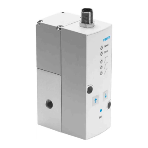
•Proportional pressure regulators
•Additional air supply via additional
pressure zones using supply plates
•Wide range of pressures
–0.9 … 10 bar
•Wide range of valve functions
•Sturdy and durable metal
components
–Valves
–Manifoldblocks
–Seals
•Fast troubleshooting thanks to LEDs
on the valves and diagnostics via
fieldbus
•Extensive operating voltage range
±25%
•Ease of servicing through
replaceable valves and electronics
modules
•Manual override either non-detent-
ing, detenting or secured against
unauthorised activation (covered)
•Durable, thanks to tried and tested
piston spool valves
•Large and durable labelling system,
suitable for barcodes
•Ready-to-install unit, already
assembled and tested
•Lower selection, ordering, installa-
tion and commissioning costs
•Secure mounting on wall or H-rail
mounting
2009/06 – Subject to change 3
Internet: www.festo.com/catalogue/...
Valve terminals type 32 MPA
Key features
Reduced downtimes:
Two-colour LED diagnostics on site
Reliable operation:
Manual override non-detenting/detenting or with cover
Width 10 mm and 20 mm
Safe:
Operating voltage connection ±25%, outputs
and valves can be disconnected separately
Compact:
Slim valves and flat plate silencers
Flexible:
– 64 valve positions/128 solenoid coils (FB)
– 24 valve positions/24 solenoid coils (MP)
Functional:
Sturdy metal thread or pre-assembled QS
fittings
Wide range of valve functions
Practical:
Large inscription labels
Quick mounting:
Directly using screws or on a H-rail,
automatic earthing
CPX diagnostic interface for hand-
held devices (channel-oriented diag-
nostics down to the individual valve)
Pneumatic interface to CPX
Straightforward electrical onnections
– Multi-pin plug connection
– Fieldbus connection
– Control block
–AS-interface
–CPI
Modular:
Supply plates facilitate the creation of
multiplepressurezonesaswellasnumer-
ous additional exhaust and supply ports
Equipment options
Valve functions
•5/2-way valve, single solenoid
•5/2-way valve, double solenoid
•2x 3/2-way valve,
normally open
•2x 3/2-way valve,
normally closed
•2x 3/2-way valve,
1x normally open,
1x normally closed
•5/3-way valve,
mid-position pressurised
•5/3-way valve,
mid-position closed
•5/3-way valve,
mid-position exhausted
•2x 2/2-way valve,
1x normally closed,
1x normally closed, reversible
•2x 2/2-way valve,
normally closed
•1x 3/2-way valve,
normally closed,
external compressed air supply
•1x 3/2-way valve,
normally open,
external compressed air supply
•Manual pressure regulators
•Proportional pressure regulators
•Pressure sensor
All valves have the same compact
dimensions with an overall length of
107 mm and a width of 10.5 mm or
21 mm. A height of 55 mm makes
them a perfect match for the electrical
peripherals CPX.
Special features
Multi-pin terminal
•Max. 24 valve positions/
max. 24 solenoid coils
•Parallel modular valve linking via
circuit boards
•Electronics module with integrated
holding current reduction
•Any compressed air supply
•Creation of pressure zones
Fieldbus terminal/control block
•Max. 64 valve positions/
max. 128 solenoid coils
•Internal CPX bus system for valve
actuation
•Module for electrical valve actua-
tion, via separate voltage supply or
without electrical isolation
•Any compressed air supply
•Creation of pressure zones
Individual valve
•Electrical M8 connection, 4-pin
with screw connection
•Detachable electronics module with
integrated holding current
reduction
AS-interface
•2 to 8 valves, freely configurable
(max. 8 solenoid coils) with input
feedback
CPI interface
•Max. 32 valve positions/
max. 32 solenoid coils
Combinable
•MPA1 flow rates up to 360 l/min
•MPA2 flow rates up to 700 l/min
•MPA1 and MPA2 can be combined
on one valve terminal
Electrical supply plate
•Increases the maximum number of
valve positions possible to 64, with
max. 128 solenoid coils
•Creation of isolated, individually
disconnectable electrical circuits
(voltage zones)
•Greater economy thanks to the
higher number of valves/solenoid
coils per valve terminal
•Greater safety through individual
disconnection of valve groups, for
example for EMERGENCY-STOP
functions
-H- Note
The electrical supply plate is
available with either an M18 or
7/8” connection.
Subject to change – 2009/06
4Internet: www.festo.com/catalogue/...
Valve terminals type 32 MPA
Key features
Valve terminal configurator Online via: www.festo.com
Selecting an MPA valve terminal using
the online catalogue is quick and easy
thanks to the convenient valve
terminal configurator provided. This
makes it much easier to find the right
product.
The valve terminals are fully
assembled according to your order
specifications and are individually
tested. This reduces the assembly and
installation time to a minimum.
The valve terminal type 32 is ordered
using the order code.
Ordering system for type 32
Internet: mpa
Ordering system for CPX
Internet: cpx
2D/3D CAD data Online via: www.festo.com
You can request the CAD data for a
valve terminal you have configured. To
do so, perform the product search as
described above. Go to the shopping
basket and click on the CAD icon
(compass). On the next page you can
generate a 3D preview or request
another data format of your choice by
e-mail.
2009/06 – Subject to change 5
Internet: www.festo.com/catalogue/...
Valve terminals type 32 MPA
Key features
Individual connection
Valves can also be used on individual
sub-bases for actuators further away
from the valve terminal.
The electrical connection is estab-
lished using a standard 4-pin M8 plug
(EN 60947-5-2).
Multi-pin plug connection
The signal flow from the controller to
the valve terminal takes place via a
pre-assembled or self-assembled
multi-wire cable to the multi-pin plug
connection, which substantially
reduces installation time.
The valve terminal can be equipped
with max. 24 solenoid coils. This
correspondsto4to24MPA1or2to
24 MPA2 valves, or a combination of
both.
Versions
•Sub-D connection
•Pre-assembled multi-pin cable
•Multi-pin cable for self-assembly
AS-interface connection
A special feature of the AS-interface is
its ability to simultaneously transmit
data and supply power via a two-wire
cable. The encoded cable profile
prevents connection with incorrect
polarity.
The valve terminal with AS-interface is
available in the following versions:
•With two to eight modular valve
positions (max. 8 solenoid coils).
This corresponds to 2 to 8 MPA1 or
2to8MPA2valves,ora
combination of both.
•With all available valve functions.
The connection technology used for
the inputs can be selected as with
CPX:M8,M12,Harax,Sub-D,
Cage Clamp® (terminals to IP20).
Further information
Internet: as-interface
CPI installation system
Valve terminal for CPI installation
system:
Valve terminals with CP connection
are intended for connection to higher-
order fieldbus nodes or to control
blocks. A fieldbus node or control
block also enables the connection of
decentralised input/output units. The
following fieldbus protocols are
supported:
•Festo fieldbus, ABB CS31,
Moeller Suconet K
•Interbus
•Allen Bradley (1771 RIO)
•DeviceNet
•Profibus DP
•Profinet IO
•CC- Link
•Modbus/TCP
•Ethernet
•EtherCAT
Four strings with up to 32 inputs and
outputs can be connected to a field-
bus node or control block. The con-
necting cables transmit the power
supply for the input modules and the
load voltage for the valves as well as
control signals.
Further information
Internet: ctec
Subject to change – 2009/06
6Internet: www.festo.com/catalogue/...
Valve terminals type 32 MPA
Key features
Fieldbus connection via the CPX system
An integrated fieldbus node manages
communication with a higher-order
PLC. This enables a space-saving
pneumatic and electronic solution.
Valve terminals with fieldbus inter-
faces can be configured with up to
16 manifold blocks. In conjunction
with MPA1 and 8 solenoid coils per
manifold block, up to 128 solenoid
coils can thus be actuated. An MPA2
with 4 solenoid coils per manifold
block can actuate 64 solenoid coils.
Versions
•Profibus DP
•ProfiNet
•Interbus
•DeviceNet connection
•CANopen
•CC- Link
•Ethernet/IP
•Front End Controller Remote
•Front End Controller
Remote I/O
•Modbus/TCP
•Profinet IO
•EtherCAT
•CPX terminal
Internet: cpx
Control block connection via the CPX system
Controllers integrated in the Festo
valve terminals enable the construc-
tion of stand-alone control units to
IP65, without control cabinets.
Using the slave operation mode, these
valve terminals can be used for intelli-
gent pre-processing and are therefore
ideal modules for designing decentra-
lised intelligence.
In the master operation mode,
terminal groups can be designed with
many options and functions which
can autonomously control a medium-
sized machine/system.
•CPX terminal
Internet: cpx
2009/06 – Subject to change 7
Internet: www.festo.com/catalogue/...
Valve terminals type 32 MPA
Peripherals overview
Modular pneumatic components
The modular design of the MPA
facilitates maximum flexibility right
from the planning stage and offers
maximum ease of service in
operation.
The system consists of manifold
blocks and valves.
The manifold blocks are screwed
together and thus form the support
system for the valves.
They contain the connection ducts for
supplying compressed air to and vent-
ing from the valve terminal as well as
the working lines for the pneumatic
drives for each valve.
Each manifold block is connected to
the next using three screws.
Individual terminal sections can be
isolated and further manifold blocks
inserted by loosening these screws.
This ensures that the valve terminal
can be rapidly and reliably extended.
Modular electrical peripherals
Themannerinwhichthevalvesare
actuated differs according to whether
youareusingamulti-pinterminal,
fieldbus terminal or individual valve.
The MPA with CPX interface is based
on the internal bus system of the CPX
andusesthisserialcommunication
system for all solenoid coils and a
range of electrical input and output
functions.
Serial linking facilitates the following:
•Transmission of switching
information
•High valve density
•Compact design
•Position-based diagnostics
•Separate voltage supply for valves
•Flexible conversion without address
shifting
•Transmission of status, parameter
and diagnostic data
Internet: cpx
•Option of CP interface
•CPX-FEC as stand-alone controller
with access via Ethernet and web
server
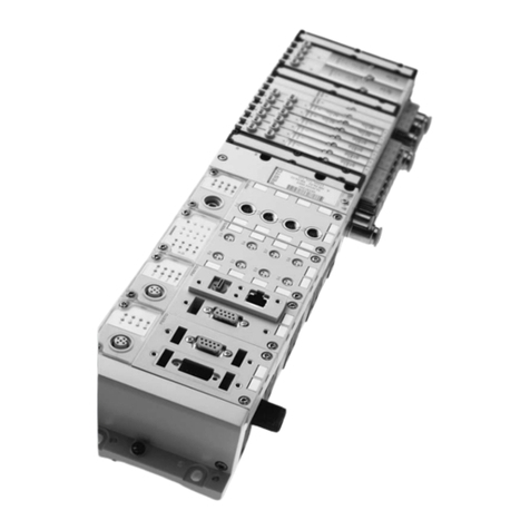
MPAwithelectricalperipheralsCPX Modularity with electrical peripherals CPX
Subject to change – 2009/06
8Internet: www.festo.com/catalogue/...
Valve terminals type 32 MPA
Peripherals overview
Individual sub-base size 1
Ordering:
•Using individual part numbers
Individual sub-bases can be equipped
with any valve.
The electrical connection is estab-
lished using a standard 4-pin M8 plug
(EN 60947-5-2).
3
2
1
7
6 5
4
Designation Brief description Page/Internet
1Solenoid valve MPA1 69
2Manual override Non-detenting/turning with detent, per solenoid coil –
3Cover cap for manual override Conversion from detenting/non-detenting to non-detenting or covered 74
4Sub-base For individual valve MPA1 71
5Fittings and/or silencers M7 for working lines (2, 4) and work air supply/exhaust ports (1, 3, 5) 76
6Fittings, silencers or blanking plugs M5 for pilot air supply/pilot exhaust air (12/14, 82/84) and pressure compensation 76
7Electrical connection M8 4-pin –
2009/06 – Subject to change 9
Internet: www.festo.com/catalogue/...
Valve terminals type 32 MPA
Peripherals overview
Individual sub-base size 2
Ordering:
•Using individual part numbers
Individual sub-bases can be equipped
with any valve.
The electrical connection is estab-
lished using a standard 4-pin M8 plug
(EN 60947-5-2).
An adjustable pressure regulator can
be installed between the manifold
block and the valve in order to control
the force of the triggered actuator.
4
3
2
1
7
6
5
Designation Brief description Page/Internet
1Solenoid valve MPA2 69
2Manual override Non-detenting/turning with detent, per solenoid coil –
3Cover cap for manual override Conversion from detenting/non-detenting to non-detenting or covered 74
4Sub-base For individual valve MPA2 71
5Fittings and/or silencers GxFor working lines (2, 4) and work air supply/exhaust ports (1, 3, 5) 76
6Fittings, silencers or blanking plugs M5 For pilot air supply/pilot exhaust air (12/14, 82/84) and pressure compensation 76
7Electrical connection M8 4-pin –
Subject to change – 2009/06
10 Internet: www.festo.com/catalogue/...
Valve terminals type 32 MPA
Peripherals overview
Pneumatic components of the valve terminal – Multi-pin plug, AS-interface
The manifold blocks are either
prepared for:
•2 or 4 single solenoid valves
•2 or 4 double solenoid valves
depending on the size.
•Double solenoid valve positions
can be equipped with any valve or a
blanking plate.
•Single solenoid valve positions can
onlybeequippedwithsingle
solenoid valves.
5
1
2
3
4
6
7
aJ
aC
aD
aE
aG
aH
aI
bJ
aB
9
8
aA
aD
aF
2009/06 – Subject to change 11
Internet: www.festo.com/catalogue/...
Valve terminals type 32 MPA
Peripherals overview
Pneumatic components of the valve terminal – Multi-pin plug, AS-interface
Designation Brief description Page/Internet
1Electronics module –73
2Solenoid valve Size 1 69
3Cover cap for manual override Conversion from detenting/non-detenting to non-detenting or covered –
4Blanking plate For unused valve position (vacant position), size 1 74
5Mounting Optional for valve terminal mounting (on supply plate) 71
6Flat plate silencer – –
7Exhaust plate For ducted exhaust air 74
8Regulator plate Size 2 70
9Solenoid valve Size 2 69
aJ Blanking plate For unused valve position (vacant position), size 2 74
aA H-rail mounting –71
aB Right-hand end plate –72
aC Separating seal For manifold block 74
aD Fittings For working lines 76
aE Inscription label –76
aF Manifold block Size 2 71
aG Fittings For pneumatic supply plate 76
aH Supply plate –74
aI Electrical manifold module For multi-pin plug connection, for AS-interface 73
bJ Manifold block Size 1 71
Subject to change – 2009/06
12 Internet: www.festo.com/catalogue/...
Valve terminals type 32 MPA
Peripherals overview
Pneumatic components of the valve terminal – CPI connection, fieldbus
The manifold blocks are either
prepared for:
•2 or 4 single solenoid valves
•2 or 4 double solenoid valves
depending on the size.
•Double solenoid valve positions
can be equipped with any valve or a
blanking plate.
•Single solenoid valve positions can
onlybeequippedwithsingle
solenoid valves.
6
1
2
3
4
5
7
8
aA
aD
aE
aF
aG
aH
aI
bA
bB
bC
aH
bE
aC
bD
aJ
9
aB
bJ
2009/06 – Subject to change 13
Internet: www.festo.com/catalogue/...
Valve terminals type 32 MPA
Peripherals overview
Pneumatic components of the valve terminal – CPI connection, fieldbus
Designation Brief description Page/Internet
1Electronics module –73
2Solenoid valve Size 1 69
3Cover cap for manual override Conversion from detenting/non-detenting to non-detenting or covered –
4Blanking plate For unused valve position (vacant position), size 1 74
5Electrical manifold module For fieldbus connection, for proportional pressure regulator 73
6Mounting Optional for valve terminal mounting (on supply plate) 71
7Flat plate silencer – –
8Exhaust plate For ducted exhaust air 74
9Mounting Optional for valve terminal mounting
(on the manifold block of the proportional pressure regulator)
71
aJ Electrical module For proportional pressure regulator 73
aA Proportional pressure regulator –64
aB Regulator plate Size 2 70
aC Solenoid valve Size 2 69
aD Blanking plate For unused valve position (vacant position), size 2 74
aE H-rail mounting –71
aF Right-hand end plate –72
aG Separating seal For manifold block 74
aH Fittings For working lines 76
aI Manifold block Size 2 71
bJ Manifold block For proportional pressure regulator 71
bA Pressure sensor –74
bB Fittings For pneumatic supply plate 76
bC Supply plate –74
bD Electrical supply plate For auxiliary voltage supply for large valve terminals 73
bE Inscription label –76
Subject to change – 2009/06
14 Internet: www.festo.com/catalogue/...
Valve terminals type 32 MPA
Peripherals overview
Valve terminal with multi-pin plug connection
Order code:
•32P-… for the pneumatic
components
•32E-… for the electrical
components
MPA valve terminals with multi-pin
plug connection can be expanded by
up to 24 solenoid coils.
The multi-pin plug connection is
designed as a removable 25-pin
Sub-D connection to IP65.
Thecablecanbeselectedwhen
ordering:
•2.5 m
•5m
•10 m
Each can be used for max. 8 or
24 valves.
1
23
4
5
6 7
Designation Brief description Page/Internet
1Inscription labels Large, for multi-pin plug connection –
2Flat plate silencer For pneumatic interface –
3Exhaust plate For ducted exhaust air 74
4Multi-pin plug connection For self-assembly 75
5Multi-pin plug connection With multi-pin cable 75
6H-rail mounting –71
7Electrical interface For multi-pin plug 72
2009/06 – Subject to change 15
Internet: www.festo.com/catalogue/...
Valve terminals type 32 MPA
Peripherals overview
Valve terminal with AS-interface connection
Order code:
•32P-… for the pneumatic
components
•52E-… for the electrical
components
MPA valve terminals with AS-interface
connection can be expanded by up to
8 solenoid coils.
4
2
3
1
5
Designation Brief description Page/Internet
1Manifold block –72
2Flat plate silencer For pneumatic interface –
3Exhaust plate For ducted exhaust air 74
4Cover – –
5Electrical interface –72
Subject to change – 2009/06
16 Internet: www.festo.com/catalogue/...
Valve terminals type 32 MPA
Peripherals overview
Valve terminal with CPI connection
Order code:
•32P-… for the pneumatic
components
•56E-… for the electrical
components
MPA valve terminals with CPI
connection can be expanded by up to
32 solenoid coils.
3
1
2
4
Designation Brief description Page/Internet
1Flat plate silencer For pneumatic interface –
2Exhaust plate For ducted exhaust air 74
3Electrical interface –72
4Inscription label Large for CPI electrical interface –
2009/06 – Subject to change 17
Internet: www.festo.com/catalogue/...
Valve terminals type 32 MPA
Peripherals overview
Valve terminal with fieldbus connection, control block (electrical peripherals CPX)
Order code:
•32P-… for the pneumatic
components
•50E-… for the electrical
components
Valve terminals with fieldbus inter-
faces can be configured with up to
16 manifold blocks. In conjunction
with MPA1 and 8 solenoid coils per
manifold block, up to 128 solenoid
coils can thus be equipped. An MPA2
with 4 solenoid coils per manifold
block can actuate 64 solenoid coils.
Each valve position can be equipped
with any valve or a blanking plate. The
rules for CPX apply to the equipment
that can be used in combination with
the electrical peripherals CPX.
In general:
•Digital inputs/outputs
•Analogue inputs/outputs
•Parameterisation of inputs and
outputs
•Integrated multi-featured
diagnostic system
•Preventive maintenance concepts
3
1
2
4
6
5
Designation Brief description Page/Internet
1Flat plate silencer For pneumatic interface –
2Exhaust plate For ducted exhaust air 74
3CPX modules – –
4Pneumatic interface For CPX modules 72
5Inscription label Large, for pneumatic interface CPX –
6H-rail mounting –71
Subject to change – 2009/06
18 Internet: www.festo.com/catalogue/...
Valve terminals type 32 MPA
Key features – Pneumatic components
Sub-base valve
MPA offers a comprehensive range of
valve functions. All valves are
equippedwithpistonspoolandpat-
ented sealing system which facilitates
efficient sealing, a broad pressure
range and long service life. To in-
crease power they have a pneumatic
pilot control supplied by pilot air.
Sub-base valves can be quickly
replaced since the tubing connectors
remain on the manifold block.
This design is also particularly flat.
Irrespective of the valve function there
are sub-base valves with one solenoid
coil (single solenoid) or with two
solenoid coils (double solenoid or two
single solenoid valves in one
housing).
Constructional design
Valve replacement Extension
The valves are attached to the metal
manifold block using two screws,
which means that they can be easily
replaced. The mechanical sturdiness
of the manifold block guarantees
excellent long-term sealing.
Blanking plates can be replaced by
valves at a later date. The dimensions,
mounting points and existing pneu-
matic installations remain unchanged
during this process.
Thevalvecode(M,J,N,NS, K,KS,H,
HS,B,G,E,X,W,D,DSI)islocatedon
the front of the valve beneath the
manual override.
Valve function
Code Circuit symbol Size Description
y
1 2
p
M
 
5/2-way valve, single solenoid
•Pneumatic spring return
•Reversible
•Suitable for vacuum
J
 
5/2-way valve, double solenoid
•Reversible
•Suitable for vacuum
N
 
2x 3/2-way valve, single solenoid
•Normally open
•Pneumatic spring return
•Operating pressure >3bar
NS
–
2x 3/2-way valve, single solenoid
•Normally open
•Mechanical spring return
•Operating pressure –0.9 …+8 bar
K
 
2x 3/2-way valve, single solenoid
•Normally closed
•Pneumatic spring return
•Operating pressure >3bar
KS
–
2x 3/2-way valve, single solenoid
•Normally closed
•Mechanical spring return
•Operating pressure –0.9 …+8 bar
2009/06 – Subject to change 19
Internet: www.festo.com/catalogue/...
Valve terminals type 32 MPA
Key features – Pneumatic components
Valve function
Code Circuit symbol Size Description
y
1 2
p
H
 
2x 3/2-way valve, single solenoid
•Normally
–1xclosed
–1xopen
•Pneumatic spring return
•Operating pressure >3bar
HS
–
2x 3/2-way valve, single solenoid
•Normally
–1xclosed
–1xopen
•Mechanical spring return
•Operating pressure –0.9 …+8 bar
B
 
5/3-way valve
•Mid-position pressurised1)
•Mechanical spring return
•Reversible
•Suitable for vacuum
G
 
5/3-way valve
•Mid-position closed1)
•Mechanical spring return
•Reversible
•Suitable for vacuum
E
 
5/3-way valve
•Mid-position exhausted1)
•Mechanical spring return
•Reversible
•Suitable for vacuum
X
 
1x 3/2-way valve, single solenoid
•Normally closed
•External compressed air supply
•Pneumatic spring return
•Reversible
Compressedair(–0.9…+10bar)suppliedatworkingport4canbe
switched with both internal and external pilot air supply.
W
 
1x 3/2-way valve, single solenoid
•Normally open
•External compressed air supply
•Pneumatic spring return
•Reversible
Compressedair(–0.9…+10bar)suppliedatworkingport2canbe
switched with both internal and external pilot air supply.
D
 
2x 2/2-way valve
•Normally closed
•Pneumatic spring return
•Operating pressure >3bar
DS
–
2x 2/2-way valve
•Normally closed
•Mechanical spring return
•Operating pressure –0.9 …+8 bar
Subject to change – 2009/06
20 Internet: www.festo.com/catalogue/...
Valve terminals type 32 MPA
Key features – Pneumatic components
Valve function
Code Circuit symbol Size Description
y
1 2
p
I
 
2x 2/2-way valve
•1x normally closed
•1x normally closed, reversible
•Pneumatic spring return
•Operating pressure >3bar
•Vacuum at port 3/5 only
1) If neither solenoid coil is energised, the valve moves to its mid-position by means of spring force.
If both coils are energised at the same time, the valve remains in the previously assumed switching position.
-H- Note
A filter must be placed upstream of valves in vacuum mode. This
prevents the ingress of foreign matter in the intake air into the valve
(e.g. when operating a suction cup).

Other Festo Controllers manuals

Festo CMMP Series Operating and installation instructions

Festo

Festo CMMP Series Operating and installation instructions

Festo DFPD-x-RS Series User manual

Festo

Festo DFPD-x-RS Series User manual

Festo CMMO-ST-C5-1-DIOP User manual

Festo

Festo CMMO-ST-C5-1-DIOP User manual

Festo CMMP-AS M0 Series User manual

Festo

Festo CMMP-AS M0 Series User manual

Festo VOFA-L26-T52-M Series User manual

Festo

Festo VOFA-L26-T52-M Series User manual

Festo CPX-E-CEC-***-PN Series User manual

Festo

Festo CPX-E-CEC-***-PN Series User manual

Festo DFPD-Series Setup guide

Festo

Festo DFPD-Series Setup guide

Festo CECC-X-M1 series Parts list manual

Festo

Festo CECC-X-M1 series Parts list manual

Festo DFPD-HD-...-HW series User manual

Festo

Festo DFPD-HD-...-HW series User manual

Festo SPC10-POT 2 Series User manual

Festo

Festo SPC10-POT 2 Series User manual

Festo EduTrainer 571849 User manual

Festo

Festo EduTrainer 571849 User manual

Festo LR G Series User manual

Festo

Festo LR G Series User manual

Festo CPX-CEC-C1 User manual

Festo

Festo CPX-CEC-C1 User manual

Festo SFC-LAC-IO Series Reference guide

Festo

Festo SFC-LAC-IO Series Reference guide

Festo SPC200 Series User manual

Festo

Festo SPC200 Series User manual

Festo SEC-AC-305-CO User manual

Festo

Festo SEC-AC-305-CO User manual

Festo SPC11 Series User manual

Festo

Festo SPC11 Series User manual

Festo CMMS-ST-C8-7 Guide

Festo

Festo CMMS-ST-C8-7 Guide

Festo CECX-K-D1 User manual

Festo

Festo CECX-K-D1 User manual

Festo SEC-AC-305 Instruction manual

Festo

Festo SEC-AC-305 Instruction manual

Festo CMXR-C1 Operating and installation instructions

Festo

Festo CMXR-C1 Operating and installation instructions

Festo VPPM C1 Series User manual

Festo

Festo VPPM C1 Series User manual

Festo CMMS-ST-C8-7 Instruction Manual

Festo

Festo CMMS-ST-C8-7 Instruction Manual

Festo CPX-CMAX Operating and installation instructions

Festo

Festo CPX-CMAX Operating and installation instructions

Popular Controllers manuals by other brands

ABB i-bus KNX product manual

ABB

ABB i-bus KNX product manual

Seneca S6001 user manual

Seneca

Seneca S6001 user manual

Axis ArgusF7Pro/65AStack manual

Axis

Axis ArgusF7Pro/65AStack manual

Seada DS2 user guide

Seada

Seada DS2 user guide

Precision Digital Corporation ProtEX-MAX PD8-6310-WM instruction manual

Precision Digital Corporation

Precision Digital Corporation ProtEX-MAX PD8-6310-WM instruction manual

Alicat Scientific MC Series Installation & maintenance instructions

Alicat Scientific

Alicat Scientific MC Series Installation & maintenance instructions

Seltron SGC26 manual

Seltron

Seltron SGC26 manual

Cypress CapSense CY8C21x34/B Design guide

Cypress

Cypress CapSense CY8C21x34/B Design guide

Technische Alternative UVR610 installation instructions

Technische Alternative

Technische Alternative UVR610 installation instructions

Smartgen HGM1790N user manual

Smartgen

Smartgen HGM1790N user manual

Danfoss VLT MCD 201 installation guide

Danfoss

Danfoss VLT MCD 201 installation guide

ControlChips CY545 manual

ControlChips

ControlChips CY545 manual

Seneca Z-PASS2-RT installation manual

Seneca

Seneca Z-PASS2-RT installation manual

Siemens Simatic S7-1500R System manual

Siemens

Siemens Simatic S7-1500R System manual

motortronics VMX-agility quick start guide

motortronics

motortronics VMX-agility quick start guide

CRC CRC-RPM user manual

CRC

CRC CRC-RPM user manual

Omron E5AR user manual

Omron

Omron E5AR user manual

Regin REGIO MINI RC-DO Instruction

Regin

Regin REGIO MINI RC-DO Instruction

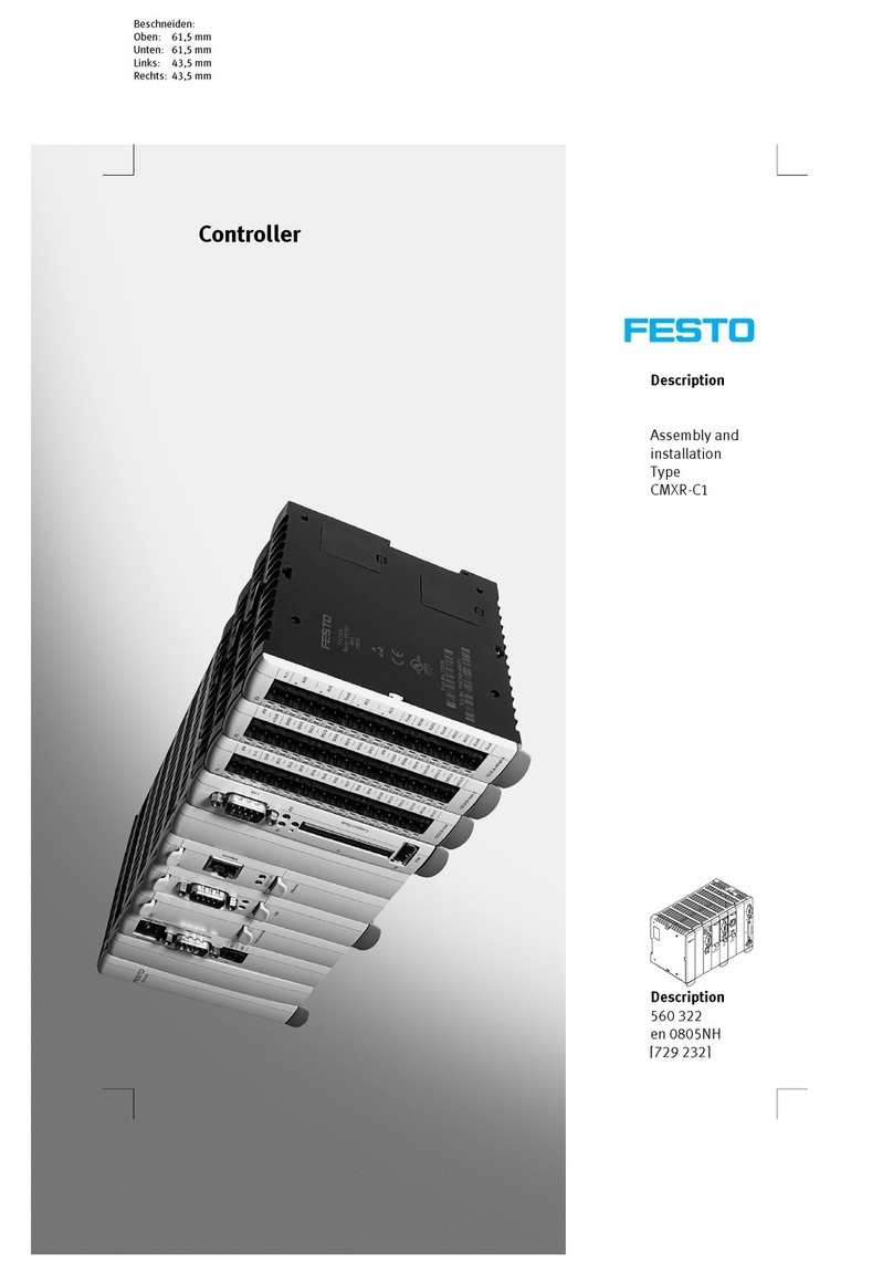
manuals.online logo
manuals.online logoBrands
  • About & Mission
  • Contact us
  • Privacy Policy
  • Terms and Conditions

Copyright 2025 Manuals.Online. All Rights Reserved.