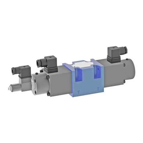
Beltrame S2007 User manual

Rev. 4.4
BELTRAME
CENTRO SERVIZI ENERGIA


2
IMPORTANT NOTICE...........................................................................................................................
1. SAFETY INSTRUCTIONS............................................................................................................
1.1 General
1.2 Safety Instrucons
2. DEVICE DESCRIPTION...............................................................................................................
2.1 Introducon
2.2 Hardware
2.2.1 Control elements and interfaces.............................................................................
2.2.2 Device connecons CN3..........................................................................................
2.2.3 Device connecons CN5
2.2.4 Device connecons CN2..........................................................................................
2.2.5 Device connecons CN4..........................................................................................
3. OPERATOR INTERFACE.............................................................................................................
3.1 Set or change parameters...................................................................................................
3.2 Navigang the menus
3.3 Menu...................................................................................................................................
3.3.1 Menu D (Display)
3.3.2 Menu P (Parameters)
4. RUNNING THE ENGINE.............................................................................................................
4.1 Running the engine
4.1.1 Starng the engine
4.1.2 Governor Performance...........................................................................................
4.2 Descripon capabilies
4.2.1 Real-Time Display
4.2.2 Pick-up detecon
4.2.3 Actuator ramp
4.2.4 Start Up Ramp.........................................................................................................
4.2.5 Speed set control
4.2.6 Variable Speed Inputs.............................................................................................
4.2.7 Idle
4.2.8 Droop
4.3 Descripon of the Protecon..............................................................................................
4.3.1 Overspeed
4.3.2 Overload
4.3.3 Loss of Pick-up signal
4.3.4 Led Signals..............................................................................................................
CONTENTS
4
5
6
7
10
11
12
12
13
14
15
16
17
18
19
20

3
5. SPECIFICATIONS.......................................................................................................................
5.1 Performance
5.2 Enviromental
5.3 Inputs/Outputs
5.4 Mechanical Details
6. NOTES ON THE OPERATION OF THE REGULATOR.......................................................................
7. SOME EXEMPLES OF TEETH NUMBER OF ENGINES FLYWHEEL...................................................
21
22
22

4
Our experience has shown that, if the informaon and recommendaons contained in this Operang Instrucons
are observed, the best possible reliability of our products is assured.
The data contained herein purports solely to describe the product and it is not a warranty of performance or
characteriscs. It is with the best interests of our customers in mind that we constantly strive to improve our
products and keep them abreast of advances in technology. This may, however, lead to discrepancies between a
product and its "Technical Descripon" or "Operang Instrucons".
This document has been carefully prepared and reviewed, however should in spite of this the reader find an error,
he is requested to inform us at his earliest convenience.
It is scarcely possible for the operang instrucons for technical equipment to cover every eventuality, which can
occur in pracce. We would therefore request you to nofy us or our agent in the case of all unusual behavior that
does not appear to be covered by these operang instrucons.
It is pointed out that all local regulaons must be observed when connecng and commissioning this equipment
in addion to these operang instrucons.
We cannot accept any responsibility for damage incurred as a result of mishandling the equipment regardless of
whether parcular reference is made in these operang instrucons or not.
We lay parcular stress on the fact that only genuine spare parts should be used for replacements.
All rights with respect to this document, including aplicaons for patent and registraon of other industrial property
rights, are reserved. Unauthorized use, in parcular reproducon or making available to third pares, is prohibited.
IMPORTANT NOTICE

1. SAFETY INSTRUCTIONS
1.1 General
The safety instrucons shall be followed during installaon, commissioning, operaon and maintenance of the
excitaon system. Read all instrucons carefully before operang the device and keep this manual for future
reference.
1.2 Safety Instrucons
The safety instrucons precede any instrucon in the context where a potenally dangerous situaon may appear.
The safety instrucons are divided into three categories, and each one is introduced by a symbol with its descripon:
Required Qualificaon
Personnel involved in installaon work and commissioning of the S2007 must be familiar, specially
instructed and informed about the residual danger areas according to the regulaons currently in
force. Operang personnel is not permied to work at the control system. Only specially instructed
personnel must carry out maintenance and repair work. The maintenance personnel must be
informed about the emergency shutdown measures and must be capable of turning off the system
in case of emergency. The maintenance personnel must be familiar with the accident prevenon
measures at their workplace and must be instructed in first aid and firefighng.
It is the owner’s responsibility to ensure that each person involved in the installaon and commis-
sioning of the S2007 has received the appropriate training or instrucons and has thoroughly read
and clearly understood the safety instrucons in this chapter.
DANGER!
This symbol indicates an imminent danger resulng from mechanical forces or high voltage.
A non-observance leads to life-threatening physical injury or death.
WARNING!
This symbol indicates a dangerous situaon. A non-observance may lead to bad or
life-threatening physical injury or death. It may cause also possible damages to the devices.
NOTICE!
This symbol emphasizes important informaon. A non-observance may cause damage to the
device or to objects close to it.
4

6
2. DEVICE DESCRIPTION
2.1 Introducon
The S2007 is an electronic device designed to control engine speed with fast and precise response to transient load
changes.
This closed loop control, when connected to a proporonal electric actuator and supplied with a magnec speed
sensor signal, will control a wide variety of engines.
This voltage regulator manages the following funcons:
1) Isocron control of the rotaon;
2) Safety controls (Overspeed and Overload);
3) Droop control for use in parallel mode.
It is designed for high reliability and built ruggedly to withstand the engine environment.
A praccal and simple-to-operate panel on the unit is used for all control operaons. In addion, user-friendly
soware facilitates commissioning and allows opmizaon of operaon.
The mechanical construcon is compact and robust.
2.2 Hardware
Structure:
The device, placed inside a plasc box, is submerged in resin allowing so the maximum resistance against engine
vibraons and a reliability with me.
Control elements:
A four digit 7-segment display is located on it in order to allow an easy visualizaon of parameters. The use of push
buons placed at the side and below the display allows to scroll the menu of all parameters and to set those of
interest.
Mounng:
The S2007 is designed for wall mounng on a metal panel.
Mounng on a non-dissipave surface such as a plasc panel may lead to device overheang and is to be avoided.
For opmal cooling is to keep free a minimum distance of 100 mm all around the unit.

7
Connecon diagram:
Basic electrical connecons are illustrated in the diagram below.
2.2.1 Control elements and interfaces
Carrying out sengs on the unit
The display and the four keys are sufficient to allow complete operaon.
All sengs can be carried out directly on the unit without addional equipment:
• Input/Output configuraon
• Parameters seng
• Display of main measures.
S2007
1 2 3 4 5 6 7 8 9 10
CN 3
ACTUATOR BATTERY
E.V.
DW
PICKUP
UP IDLE
+
-
12 or 24 V
+
+-
-
Respect polarities only for
actuators or Pickup where is
indicated positive (+) and
negative (-).

8
Terminal Boards:
Overview of the device connectors.
108
137
LD1
LD7
LD6
LD4
LD3
P2
P4
P3
P1
LD2 LD5
CN 3
CN 2 CN 4
CN 5
1 2 3456 7 8 9 10
Up
Down
EnterSelect
1
2
3
4
5
6
7
8
15
69

9
Connectors
CN2 – CAN BUS Interface CN4 – RS232 Interface
1CAN H
CAN L
GND CAN
n.c.
n.c.
n.c.
GND CAN
n.c.
Actuator
Actuator
Baery – (GND/COM)
Baery + (12÷24Vdc)
Out aux (Solenoid valve)
PickUp
PickUp
UP (COM=GND)
Digital input (COM=GND)
Digital input (COM=GND, enabled droop)
GND/COM
Analog input 0÷10V
Supply output +10V (20mA)
Analog input 4÷20mA
Analog input -5÷5V
GND/COM
DOWN (COM=GND)
IDLE (COM=GND)
n.c. = not connected
2
3
4
5
6
7
8
1
2
3
4
5
6
7
8
1
2
3
4
5
6
7
8
9
10
CN3 - Inputs/Outputs CN5 – Inputs/Outputs
1Reserved ( do NOT use or connect!)
Tx (from regolator to PC)
Rx (from PC to regolator)
Reserved ( do NOT use or connect!)
GND
Reserved ( do NOT use or connect!)
Reserved ( do NOT use or connect!)
Reserved ( do NOT use or connect!)
Reserved ( do NOT use or connect!)
2
3
4
5
6
7
8
9
_
_
+
+
NB: Respect polaries only for actuators or
PickUp where is indicated posive (+) and
negav (-).

10
2.2.2 Device connecons CN3
2.2.3 Device connecons CN5
Terminal
designaon
DC output 12÷24Vdc
0÷12 A (15A for 10s)
Or
Actuator
12÷24Vdc
2A max
Digital output
Solenoid valve
Passive Pickup
Acve Pickup
N.B. Open jumper J1
Pickup
Digital Input
Up
Digital Input
Down
Digital Input
IDLE
Signal Specificaons
Terminal
designaon Signal
2 digital InputDigital Input
• Programmable funcon
• 10V 5mA
Specificaons
RESPECT PICK UP
POLARITIES
CN 3
GND
GND
Pickup+
+12/24V
+12/24V
Pickup-
7
6
4
3
Pickup
PNP
CN 3
Pickup
Pickup
7
6
Pickup
CN 3
GND
GND
Pickup+
+12/24V
+12/24V
Pickup-
7
6
4
3
Pickup
NPN 1Kohm
CN 3
GND
DOWN
UP
IDLE
10
9
8
3
CN 5
input 2
input 1
GND
3
2
1

11
Terminal
designaon
Analog Input
0÷10Vdc
(Potenometer=
2kΩ ÷ 5kΩ 0,25W)
Analog Input
4÷20mA
Analog Input
-5V ÷ +5V
Analog input
Signal Specificaons
N.B.: Inputs 0÷10V
and 4÷20mA are to be
used one at a me.
They can’t operate
simultaneously.
2.2.4 Device connecons CN2
Terminal
designaon Signal
CANComunicaon
(Oponal)
• Selectable terminaon
• CANopen and proprietary
protocols
Specificaons
CN 5
GND
3
0-10V
4
10V
5
CN 5
GND
8
4-20mA
6
CN 5
GND
8
-5V ÷ +5V
7
1 CAN H
2 CAN L
3 GND
jp2
120

12
2.2.5 Device connecons CN4
3. OPERATOR INTERFACE
In this following charter are described the operaons of management parameter using the integrated display.
3.1 Set or change parameters
Many parameters can be accessed using the intergrated display and keys.
Terminal
designaon Signal
RS232Communicaon
Specificaons
To connect a device such as a notebook or personal computer at the Digital controller
revoluons S2007, an USB/RS232 or RS232/RS232 adapter is needed. Please request it directly
to BELTRAME CSE.
NEVER CONNECT TRADE CABLES (more than three conductors)!
SELECT
ENTER
UP
DOWN
It is possible to enter the menus through the funcons of the configuraon push-buons
Display of data menu “d”
Display/Modify menu parameters seng “P”
d.XXX
P.XXX
Select viewing menu (d.xxx) or parameters menu (P.xxx)
Select or save current displayed parameter
Increase parameter number or value
Decrease parameter number or value
2 Tx
3 Rx
5 GND
10
22
22
Led 4
Led 5
Led 7
Led 6
SELECT ENTER
UP
DOWN
Data menu, viewing only
Parameters menù

13
3.2 Navigang the menus
When the S2007 is power on, the display automacally shows parameter d.000 (Engine speed) in the Display menu.
Example: how to change a SPEED reference
Select
Select
Select
Switch On Regulator
Versione firmwareFirmware version
Versione firmwareEngine speed
3 seconds
Versione firmware
Data menù
display d.000
Versione firmware
Parameters menù P.000
Select Enter
Select
Enter
Down
Up
Engine
speed d.000 P.000
1501 rpm
1500 rpm
1499 rpm
SpeedSpeed
To conrm new
setting desired
Exit without save
Select

14
3.3 Menù
3.3.1 Menù D (Display)
3.3.2 Menù P (Parameters)
Display Parameter Descripon Units
D.000
D.001
Engine speed
Speed set
Actual engine speed Rpm
Rpm
Speed set point
D.004
D.005
Input 0÷10V
Input 4÷20mA
0÷10V analog input voltage V
mA
4÷20mA analog input current
D.006
D.007
V Ba Baery voltage V
Firmware version
D.002
D.003
Actuator current
Actuator voltage
Current supplied to actuator A
V
Voltage supplied to actuator
Parameter Parameter Descripon Units Default Range
P.000
P.001
Rated Speed
Kp (GAIN)
Engine speed Set Point Rpm
Rpm
600 - 4000
20 - 5000
1150
150
0 - 5000
140
Proporonal gain for PID control loop.
The system becomes more reacve at
the value increasing.
P.002 Ki (STABILITY)
Integral gain for PID control loop.
The system becomes more reacve at
the value increasing.
0 - 5000
80
P.003 Kd (DEADTIME)
Integral gain for PID control loop.
The system becomes more reacve at
the value increasing.
600 - 4000
1300
P.004 IDLE Sets engine speed when the IDLE
input is connected to GND/COM
Rpm
600 - 4000
1200
P.005 Crank speed
Crank terminaon threshold: RPM
when the governor changes from
crank mode to control mode
s
0,5 - 60
5
P.008 Speed ramp Time to change speed from crank
speed to rated speed
A
1 - 15
10
P.010 Max current
Droop at maximun actuator current
5% - 100%
100%
P.007 Start fuel Max output to actuator while cranking
0,1% - 8%
1,5%
P.009 Droop Droop at maximun actuator current
Rpm
1350 - 4750
1700
P.006 Over speed
Over speed: RPM when actuator is
shut off for safety reason and acve
an overspeed alarm
P.011 Overload me
5 - 60
10s
0% - 100%
3%
Time before actuator current is
clamped to Max current (P.010)
P.012 Variable speed control Maximum speed change from analog
inputs
10 - 250
72
P.013 Teeth Number of teeth on flywheel
1 - 200
20
P.014 Rate Time of the PID acon

15
P.015 Reset
PW: 333.
Seng P.015 at the value of 333 (pw)
and selecng “Enter” is possible to
restore all regulator parameters at the
default values, except the parameter
“P013 flywheel teeth number”.
The present manual refers to the firmware version 1.3.4 and following updang.
* NOTICE!
In case of short circuit at actuator output the S2007 goes in Alarm Mode to prevent from device
failure.
To recover from Alarm Mode shut off the S2007, remove short circuit then switch on again
the S2007.
4. RUNNING THE ENGINE
4.1 Running the Engine
4.1.1 Starng the Engine
Power the regulator before starng engine. The actuator remains in rest posion unl the detecon of the
minimum starng threshold (100Hz). Once the threshold is exceeded, the speed controller command the opening
of the actuator in ramp, and aer have completed the engine cranking, ramps up to the set point engine.
NOTICE!
If engine speed is unstable aer start up, adjust GAIN (P.001), STABILITY (P.002), and DEADTIME
COMPENSATION (P.003) unl engine speed is stabilized.
Once rated speed is achieved, PID parameters may required further fine adjustment.
On
Waing for
revoluon
Pick-Up Detected >
100HZ
Waing actuator
posion 0%
Opening actuator
in ramp
Speed ramp
controlled

16
4.1.2 Governor Performance
Once the engine is at rated speed and at no load, the following governor performance adjustment can be made:
A. Increase GAIN parameter unl motor speed reaches instability. Gradually decrease the Gain unl
stability is recovered. Decrease one count further to insure stable performance.
B. Increase STABILITY parameter unl motor speed reaches instability. Gradually decrease Stability
unl stability is recovered. Decrease one count further to insure stable performance. If no instability
appears, leave default value.
C. Increase DEADTIME parameter unl motor speed reaches instability. Gradually decrease Deadme
unl stability is recovered. Decrease one count further to insure stable performance. If no instability
appears, leave default value.
D. This seng made with no load grants normally good performances with load too. However it can
happened that an adjustment of the three parameters may be necessary aer having applied load
to the engine.
4.2 Descripon capabilies
4.2.1 Real-Time Display
While engine runs, S2007 Digital Speed Governor can display real me measures and other useful
informaon (see table below). Cycle through the table with UP / DOWN keys.
4.2.2 Pickup detecon
The speed regulator supplies energy to the actuator only if the pickup signal is higher than 100Hz and remains so
stable for at least 100ms me.
4.2.3 Actuator ramp
Once obtained the signal of the pickups, the speed regulator supplies a raising current in ramp allowing the flow of
fuel.
A controlled ramp is programmed from 0 (zero) to the percentage value previously set through the parameter P.007
(maximum actuator value) in a me fixed in 1 (one) second.
Example: the parameter P.007 is set at 75% and the ramp me value is 1 second per default, the pwm increases
in a linear way from 0 to 75% in one second.
Display Parameter Descripon Unit
D.000
D.001
Engine speed
Speed set
Actual engine speed Rpm
Rpm
Speed set point
D.004
D.005
Input 0-10V
Input 4-20mA
0-10V Input voltage V
mA
4-20mA Input current
D.006
D.007
V Ba Baery voltage V
Firmware version
D.002
D.003
Actuator current
Actuator voltage
Actual actuator current A
V
Actual actuator voltage

17
Example: the parameter P.007 is set at 75% and the ramp me value is 1 second per default, the pwm increases
in a linear way from 0 to 75% in one second.
In this phase the speed regulator controls connuously the frequency input at the regulator’s pickup input and
when the frequency exceeds stably the value of the Minimum Speed Set (P.005), the speed regulator switches to the
PID control.
4.2.4 Start Up Ramp
The Speed Ramp (P.008) seng is used to reduce excess fuel and thus black smoke during startup. Aer cranking,
Speed Ramp represents how fast the motor reaches the rated speed (P.000).
4.2.5 Speed set control
This is the main running status of the speed regulator. The regulator follows the Nominal Speed Set (P.000).
In this status:
1. The closing of the UP/Down external inputs causes a variaon of the speed set, changing the preset
value in parameter P.000. This variaon is not saved and stored.
The variaon has a fixed slope of 10Hz per second (the rpm slope depends from the number of the
wheel’s teeth).
The revoluons’ set varies within the limits set through the parameter Max. Variaon Set (P.012).
Example: The Rpm Nominal Set (P.000) is set up at 1500rpm. The Max. Variaon Set (P.012) is set up
at 3%. In this situaon a closing of the Down Input for an undefined me will decrease the rpm
number unl the minimum value of 1455 rpm; while a closing of the Up input for an undefined me
will increase the rpm number unl 1545rpm.
2. The closing of IDLE input switches the speed regulator in IDLE mode (see below).
3. In case of a voltage exceeding 0,3Vdc on the 0-10V input (or on the 4-20mA input) switches the
system in the Analogic Variaon mode of the Set.
4. The closing of the DROOP enabling input (input 2) enable the DROOP mode (see below).
A variaon of the P.000 parameter (Nominal Rpm set) through the keyboard, involves a real me variaon of the
Rotaon System Set.
Even a variaon of the control parameters PID (P.001=Kp, P.002=Ki, P003=Kd, P.014=intervenon me) is done in
real me to allow a fast tuning of the parameters themselves.
NOTE: with an alternator 4 poles 50Hz = 1500RPM
60Hz = 1800RPM

18
4.2.6 Variable Speed Inputs
If a voltage above/exceeding 0,3V is detected on the 0-10V input (or 4-20mA) during the Rpm Control Set phase, the
regulator enable the Analogic Variaon of the Set. In this phase the followed Rpm Set is set up through the analog
input with connuous variaon of the set as a funcon of the value on the analog input. During this phase the
inputs UP/DOWN and DROOP are disabled. The variaon limit is always given by the parameter Max. Variaon Set
(P.012).
Example: The Rpm Nominal Set (P.000) is set up at 1500rpm. The Max. Rpm Variaon Set (P.012) is set up at 3%. In
this situaon a voltage equal to 0,4Vdc on the analog input will bring the rotaon set to 1455rpm, while a voltage
equal to 10Vdc will bring the rotaon to 1545rpm.
The input 4-20mA for the microcontroller looks like the 0-10V input and acts exactly in the same way.
If the value of the analog input decreases below
0,3V following again the RPM Nominal Set, the
regulator comes back to the Rpm Set Control
(P.000).
4.2.7 Idle
IDLE is a feature that allows to run the motor at
reduced speed.
Upon closing the input Idle, the speed governor changes in a step the motor speed from the Set RPM Nominal
(P.000) to the Set RPM Idle (P.004).
The rotaon speed remains set to this value for all the me that the IDLE input remains closed.
Opening the IDLE input, the regulator performs a controlled ramp from the Set RPM IDLE (P.004) to the Set RPM
nominal (P.000) in a me equal to the one set for the Speed Ramp (P.008).
4.2.8 Droop
The Droop funcon is pically used for parallel
between generators.
This funcon makes reducon of the engine
speed as a funcon of the actuator control
current.
Unl the input 2 is closed, the speed governor
makes a downward correcon of the Set RPM
Nominal (P.000) as a funcon of current supplied
to the actuator.
Increasing the current, the number of
revoluons is decreased in an inversely
proporonal manner. The maximum percentage
change the number of revoluons is given by Droop parameter (P.009) and happens at the set of maximum current
(P.010).
Example: The Nominal Set Revoluons (P.000) is set to 1500rpm, the Maximum Current (P.010) of 6Adc, the Droop
(P.009) to 1%. As the current increases on the actuator of the rotaon set is equal to 1485rpm.
If instead the current on the actuator is 3Adc, the rotaon set is equal to 1492rpm.
Speed [rpm]
Nominal Set
Set IDLE
Speed ramp
P.008
IDLE ON OFF
Time [s]
OFF
Motor Speed
100%
99,5%
99%
Droop = 1%
NO DROOP
SI DROOP
Actuator
current
100%50%

19
4.3 Descripon of the Protecon
4.3.1 Over speed
If, during the operaon, the Rpm value is higher
than the value over speed set (P.006) for a me
exceeding 1200ms, the rpm regulator switch off the
generang set.
The actuator goes immediately (<1ms) in pause
posion and the aux. output (electrovalve) is
disabled.
The rpm regulator remains in this status unl the
switching off.
If the number of teeth or the value of the overspeed parameter is not correctly set you
may having unwanted intervenons or lack of operaons.
It's recommended not to rely on this protecon if the entered parameters are not
correct.
4.3.2 Overload
The regulator controls the actuator’s voltage during the operaon. When the requested current is higher than the
Max. Current (P.010) the regulator allows an overload for a me to be set up through the parameter Overload Time
(P.011). Once the set me finishes, the regulator limits the current at the set up value of Max. Current (P.010) even
if the engine speed decrease. When the load condion decreases the regulator follows again the RPM Nominal Set.
4.3.3 Loss of Pick-Up signal
If the regulator looses the pick-up signal during the running, the actuator goes automacally (<1ms) in pause mode
and disables the command/control of the auxiliary output electrovalve (block). The Speed regulator remains indefi-
nitely in this status unl the switching off.
Overspeed
Nominal set
[%]
Machine rpm
Current actuator
Reset
Actuator
Electrovalve
Allarm status
ON
ON
OFF
ON
ON
OFF
OFF
OFF
ON
Other manuals for S2007
1
Table of contents
Popular Control Unit manuals by other brands

Panasonic
Panasonic PAN1760A Product specification

Chemtrac
Chemtrac Auto Clean UV254 owner's manual
Distech Controls
Distech Controls IO-R-16 Wiring guide
EastRising Technology
EastRising Technology ER-OLED0.91-1 user manual
NuAire
NuAire ES-LCD Installation & operating instructions
AMX
AMX RDA-CKM Wiring diagram
SIGLENT
SIGLENT SEM5000A Series quick start
Festo
Festo VIFB-21 Series manual
Hach
Hach SC4200c User instructions
Vixen Horns
Vixen Horns VXA7164B installation guide
Westinghouse
Westinghouse 7880040 Installation and operating instructions
Pfeiffer Vacuum
Pfeiffer Vacuum DualGauge TPG 262 operating instructions
