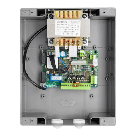
Beninca DA.C20 User manual

DA.C20
CENTRALINA A MICROPROCESSORE
CONTROL UNIT WITH MICROCONTROLLER
MIKROCONTROLLER-STEUERUNG
CENTRALE A MICROCONTRÔLEUR
CENTRALITA A MICROPROCESADOR
AUTOMATISMI PER CANCELLI
®
L8542615
Rev. 01/99/00
Libro istruzioni
Operating instructions
Betriebsanleitung
Livret d’instructions
Libro de instrucciones
UNIONE NAZIONALE COSTRUTTORI
AUTOMATISMI PER CANCELLI, PORTE,
SERRANDE ED AFFINI
A
Z
I
E
N
D
A
C
E
R
T
I
F
I
C
A
T
A
UNI
EN ISO
9001

2
Dichiarazione CE di conformità Déclaration CE de conformité
EC declaration of confirmity Declaracion CE de conformidad
EG-Konformitatserklarung
Con la presente dichiariamo che il nostro prodotto
We hereby declare that our product
Hiermit erklaren wir, dass unser Produkt
Nous déclarons par la présente que notre produit
Por la presente declaramos que nuestro producto
DA.C20
è conforme alle seguenti disposizioni pertinenti:
complies with the following relevant provisions:
folgenden einschlagigen Bestimmungen entspricht:
correspond aux dispositions pertinentes suivantes:
satisface las disposiciones pertinentes siguientes:
Direttiva sulla compatibilità elettromagnetica (89/336/
CCE, 93/68/CEE)
EMC guidelines (89/336/EEC, 93/68/EEC)
EMV-Richtlinie (89/336/EWG, 93/68/EWG)
Directive EMV (89/336/CCE, 93/68/CEE) (Compatibilité
électromagnétique)
Reglamento de compatibilidad electromagnética (89/336/
MCE, 93/68/MCE)
Norme armonizzate applicate in particolare:
Applied harmonized standards, in particular:
Angewendete harmonisierte Normen, insbesondere:
Normes harmonisée utilisées, notamment:
Normas armonizadas utilzadas particularmente:
EN 55022, EN 61000-3-2, EN 61000-3-3, EN 50082-1
Norme e specifiche tecniche nazionali applicate in
particolare:
Applied national technical standards and specifications, in
particular:
Angewendete nationale Normen und technische
Spezifikationen, insbesondere:
Normes et specifications techniques nationales qui ont été
utilisées, notamment:
Normas y especificaciones técnicas nacionales que se
utilizaron particularmente:
UNI 8612
Data/Firma
Direttiva sulla bassa tensione (73/23/CEE, 93/68/CEE)
Low voltage guidelines (73/23/EEC, 93/68/EEC)
Tiefe Spannung Richtlinie (73/23/EWG, 93/68/EWG)
Directive bas voltage (73/23/CEE, 93/68/CEE)
Reglamento de bajo Voltaje (73/23/MCE, 93/68/MCE)
Norme armonizzate applicate in particolare:
Applied harmonized standards, in particular:
Angewendete harmonisierte Normen, insbesondere:
Normes harmonisée utilisées, notamment:
Normas armonizadas utilzadas particularmente:
EN 60204-1, EN 60335-1
Data/Firma
AUTOMATISMI PER CANCELLI
®
Automatismi Benincà Srl
Via Scamozzi, 3
36030 MONTECCHIO P. VI
ITALIA

3
Centralina DA.C20
Quadro di comando per un motore monofase 230Vac o trifase 380Vac ±10%.
Quadro elettronico con funzioni di comando e controllo interamente programmabili assistite da logica a micro-
processore su scheda estraibile.
Esso è indicato per movimentazioni che prevedono l’uso di un motore trifase 380Vac, 2.2kW max. o un motore
monofase 230Vac, 1.5kW max.
Il tipo di costruzione e le sicurezze previste lo rendono particolarmente indicato per installazione in ambiente
industriale o comunque ove sia previsto un uso intensivo.
Caratteristiche
• Interruzione bi/tripolare del carico a mezzo teleinvertitore con interblocco meccanico.
• Morsettiera di arrivo della linea a norme con terna di fusibili industriali ed interruttore generale con funzione
di bloccoporta lucchettabile.
• Protezione contro i cortocircuiti e le extracorrenti a fusibile sulle tre fasi, sulla linea del trasformatore e sulla
linea a bassa tensione.
• Protezione contro le sovratensioni di linea a varistore su primario e secondario del trasformatore.
• Possibilità di comando tramite un unico pulsante con funzione Apre-Chiude-Apre oppure tramite
radiocomando, inserendo un ricevitore nel connettore predisposto.
• Pulsante di apertura.
• Pulsante di chiusura.
• Pulsante di Stop.
• Ingressi contatti finecorsa di apertura e chiusura.
• Ingresso contatto fotodispositivi.
• Ingresso contatto costa fissa.
• Uscita per il collegamento di lampeggiatore 230Vac, 200W max.
• Funzione semaforica (utilizzare lampade 230Vac, 200W max.).
• Uscita per elettroserratura (12Vac, 20W max.).
• Uscita luce di cortesia attiva a 24Vcc (abilitazione relè).
• Uscita alimentazione accessori (24Vac, 10W max.).
• Spie per autodiagnosi dei cablaggi ausiliari.
Opzioni
• Scheda radiocomando ad innesto, superreattiva o quarzata, monocanale o bicanale, con funzione Passo-
Passo e con uscita 2°canale disponibile sulla base.
• Uscita spia cancello aperto (24Vac, 5W max.). A richiesta togliendo la semaforica.
Funzioni
• Tempo di lavoro regolabile.
• Richiusura automatica con tempo di pausa regolabile.
• Funzione condominiale selezionabile.
• Selezione modo di funzionamento (automatico, semiautomatico o manuale).
• Selezione modalità di intervento dei fotodispositivi.

4
Connettore 20 pin
ABC
D
E
P1
P2 P3
Modo di
funzionam.
Prolung. tempi fissi
Selettore funzioni
Prolung. tempo di lavoro
Reg. tempo lavoro
1
1234
2
Reg. tempo pausa
Non usato
Funzioni della scheda logica
A Regolazione del tempo di lavoro: ruotando la vite del trimmer è possibile variare il tempo di lavoro da un
minimo di 1 secondo (vite completamente ruotata in senso antiorario) ad un massimo di 40 secondi (vite
completamente ruotata in senso orario).
B Regolazione del tempo di pausa: ruotando la vite del trimmer è possibile variare il tempo di pausa da un
minimo di 1 secondo (vite completamente ruotata in senso antiorario) ad un massimo di 100 secondi (vite
completamente ruotata in senso orario). La regolazione va fatta con la funzione Richiusura automatica
inserita (Dip-switch 3 del selettore funzioni in posizione ON).
CNon usato.
D Dip-switch 1 non usato: lasciare il Dip-switch 1 in posizione OFF.
Esclusione di inversione di marcia (funzione condominiale).
Dip-switch 2 in posizione Off disabilita il comando Passo-Passo durante la fase di apertura.
Richiusura automatica.
Dip-switch 3 in posizione On abilita la richiusura automatica dopo il tempo regolato dal trimmer B.
Selezione intervento fotocellule.
Dip-switch 4 in posizione On le fotocellule intervengono anche in fase di apertura, fermando il cancello
finchè l’ostacolo non viene rimosso. In posizione Off le fotocellule agiscono solo in chiusura; il loro interven-
to provoca l’inversione di marcia.
E Modo di funzionamento automatico.
Dip-switch 1 On - Dip-switch 2 On. Un impulso di passo-passo o di apertura da inizio al ciclo di apertura che
prosegue fino all’intervento del finecorsa o fino al termine del tempo di lavoro impostato. Durante il ciclo di
apertura non è possibile invertire il moto con il pulsante di chiusura, ma solo con il passo-passo se abilitato.
Per il ciclo di chiusura si ha un funzionamento analogo. Se è necessario invertire il moto dalla pulsantiera,
dare prima un impulso di Stop e dare poi il comando inverso oppure bisogna attendere l’intervento dei
finecorsa o la fine del tempo di lavoro.
Modo di funzionamento manuale.
Dip-switch 1 Off - Dip-switch 2 Off. Il cancello effettua la manovra di apertura o chiusura solo se si mantiene
premuto il relativo pulsante. Rilasciando il pulsante il cancello si ferma così come per l’intervento dei finecorsa
o alla fine del tempo di lavoro, a pulsante premuto.
L’arresto del cancello si ha anche all’intervento della fotocellula o della costa fissa. Se la fotocellula inter-
viene durante la chiusura, dopo l’arresto del cancello è possibile: A) rilasciare il pulsante di chiusura e
premere quello di apertura; B) rilasciare il pulsante di chiusura, premere lo Stop e premere uno dei pulsanti
di apertura o chiusura; C) attendere la fine del tempo di lavoro e premere uno dei pulsanti di apertura o
chiusura. Durante la manovra manuale con pulsanti, un impulso dal radiocomando (o dal pulsante passo-
passo) arresta il cancello: procedere in uno dei modi A), B) o C).
Modo di funzionamento semiautomatico.
Dip-switch 1 Off - Dip-switch 2 On. In apertura il funzionamento è automatico, in chiusura è manuale.
Dip-switch 1 On - Dip-switch 2 Off. In chiusura il funzionamento è automatico, in apertura è manuale.
P3 Prolungamento del tempo di lavoro: tagliando il ponticello P3 si prolunga il tempo di lavoro; la regolazione
con il trimmer A va da un minimo di 40 ad un massimo di 80 secondi.
P2 Prolungamento del tempo di frenatura, del prelampeggio e dell’elettroserratura: tagliare il ponticello
P2 per prolungare questi tempi fissi da 1.5 a 2 secondi.
P1 Tagliare il ponticello P1 se, dopo aver tagliato il ponticello P2, l’elettroserratura resta in funzione troppo a
lungo.
5
Installazione e collegamenti
230Vac
380Vac
Linea trifase 380Vac
Fusibili 10A, 500V
Interruttore generale
Fusibile 1.6A
Fusibile 2.5A
Ritardato
Teleruttore trifase
Trasformatore
Luce cortesia
Connettore 15 poli
Antenna
Scheda logica
Ricevitore
Bloccoporta
Linea 230Vac
Uscita
servizi 24Vac
(U) N(V) (W)
VUW
M
RST
Ch.
Ap.
Spia
cancello
aperto
Comando di stop
Contatto fotodispositivo
Comando passo passo
Com
Neutro per il
collegamento trifase
Fase ”S” per il
collegamento monofase
Contatto pulito
N.A. 2 Ch. radio Rosso
Connettore 15 poli
Descrizione semaforica
Cancello aperto: semaforo rosso acceso; verde spento
Cancello chiuso: semaforo verde acceso; rosso spento
LP Verde
Elettroserratura (12Vac)
Comando di chiusura
Comando di apertura
Contatto di finecorsa in chiusura
Contatto di finecorsa in apertura
Contatto di costa fissa
S
E
M
A
F
O
R
I
C
A
Attenzione!
In caso di collegamento alla linea trifase collegare al morsetto N il cavo di neutro del trifase.
In caso di collegamento monofase collegare al morsetto N la fase denominata con S sull’interruttore
bloccoporta.

6
Fissare il quadro in posizione verticale e, se possibile, in posizione riparata. Effettuare i collegamenti tenendo
presente che:
• per il circuito di potenza (motore, linea) i cavi devono essere del tipo prescritto e di sezione appropriata alle
potenze in gioco; è consigliabile tenere i cavi di potenza distinti da quelli di comando.
Per evitare interferenze è preferibile prevedere ed utilizzare 2 guaine separate (vedi EN 60204-1 15.1.3);
• se il motore è monofase il condensatore va collegato tra il morsetto Apre ed il morsetto Chiude;
• gli ingressi non utilizzati vanno lasciati aperti se di tipo N.A., oppure ponticellati verso il comune (COM) se
di tipo N.C.;
• nel caso si debbano usare più pulsanti o contatti con uguale funzione, quelli facenti capo a linee N.A. vanno
posti in parallelo e quelli facenti capo a linee N.C. vanno posti in serie;
• i led di diagnosi delle linee N.A. devono essere normalmente spenti, quelli delle linee N.C. devono essere
accesi;
• se le linee di comando sono eccessivamente lunghe (più di 50 metri) è necessario interporre tra queste e il
quadro dei relè di disaccoppiamento in prossimità delle morsettiere.
Porre l’automazione a mezza corsa e dare un comando di apertura; se il movimento è in chiusura togliere
alimentazione ed invertire due fasi del motore (trifase) o gli avvolgimenti di Apertura e Chiusura (monofase).
Regolare il tempo di lavoro affinchè sia di 4 o 5 secondi superiore al tempo necessario al movimento.
Collaudare le sicurezze e quindi regolare le funzioni accessorie.

7
Switchboard DA.C20
Switchboard for a 230Vac monophase motor or 380Vac triphase motor ±10%.
Electronic switchboard with command and control functions which are completely programmable and
controlled by a microprocessor logic card on an extractable board. It is adapted to the control of move-
ments which need a 380Vac triphase motor, 2.2kW max. or a 230Vac monophase motor, 1.5kW max.
Its manufacture and securities make it especially adapted to the installation in industrial sites or where
there is an intensive use.
Characteristics:
• Bi/tripolar interruption of the load through a remote control inverter with mechanical interlocking.
• Terminal block of arrival according to the standards with triad of industrial fuses and general switch
with function of padlock door-locking.
• Fuse protection on the three phases against the short-circuits and the extra-voltages on the trans-
former and the low voltage lines.
• Varistor protection against the line survoltages on the transformer primary and secondary.
• Possibility to command by means of a push-button with function Opens-Closes_Opens or by means
of a radio-control, by inserting a receiver in the preset connector.
• Aperture push-button.
• Closing push-button.
• Stop push-button.
• Inputs of aperture and closing limit switch contacts.
• Input of photo-devices contact.
• Input of fixed rubber tube contact.
• Output for the connection of a 230Vac, 200W max. blinker.
• Semaphore function (use 230Vac, 200W max. lamps).
• Electro-lock output (12Vac, 20W max.).
• Courtesy light output active at 24Vcc (relay activation).
• Output for accessory supply (24Vac, 10W max.).
• Pilots for auto-control of the auxiliary cablings.
Options
• Clutch radio-control boards, superreactive or quartz, mono or bi-channel, with Step-by-step func-
tion and 2nd channel output available on the basis.
• Open gate pilot output (24Vac, 5W max.). On request by removing the semaphore.
Functions
• Adjustable working time.
• Automatic closing with adjustable pause time.
• Selectable condominium function.
• Functioning mode selection (automatic, semi-automatic or manual).
• Selection of the photo-devices intervention modes.

8
Central unit board functions
20 pin connector
ABC
D
E
P1
P2 P3
Functioning
mode
Prol. fixed times
Functions selector Prol. working time
Working time adj.
1
1234
2
Pause time adj.
Not used
A Working time adjustment: by turning the trimmer screw it is possible to vary the working time from
minimum 1 s (screw is completely turned counterclockwise) to maximum 40 s (screw is completely
turned clockwise).
B Pause time adjustment: by turning the trimmer screw it is possible to vary the pause time from
minimum 1 s (screw is completely turned counterclockwise) to maximum 100 s (screw is com-
pletely turned clockwise). The adjustement is to be made with the function of Automatic closing
inserted (Dip-switch 3 of the Functions selector in On position).
C Not used.
D Dip-switch 1 not used: Let Dip-switch 1 in Off.
Exclusion of the reversal (Condominium function).
Dip-switch 2 in Off position. It deactivates the Step-by-step command during the aperture phase.
Automatic closing
Dip-switch 3 in On position. It activates the automatic closing after a time regulated by trimmer B.
Selection of the photo device intervention.
Dip-switch 4 in On position. The photo-devices intervene also in the aperture phase, stopping the
gate up to when the obstacle is removed. In Off position, the photo-devices operate only in closing;
their intervention causes the reversal.
E Functioning mode:
Automatic: Dip-switch 1 On - Dip-switch 2 On. A step-by-step or Aperture impulse makes the aper-
ture cycle begin which goes on till the intervention of the limit switch or to the end of the set work-
ing time. During the aperture cycle it is not possible to invert the movement by means of the closing
push-button, but only by means of the step-by-step if activated. There is a similar functioning for
the closing cycle. If it is necessary to invert the movement from the push-button panel, give a Stop
impulse and then the opposed command or wait for the limit switches intervention or the end of the
working time.
Manual: Dip-switch 1 Off - Dip-switch 2 Off. The gate operates the aperture or closing manoeuvre
only if the correspondent push-button is kept pressed. When the push-button is released the gate
stops as for the limit switches intervention or at the end of the working time, at push-button pressed.
The gate stops also at the intervention of the photo-cell or the fixed rubber tube. If the photo-cell
intervenes during the closing phase, after the stop of the gate it is possible: A) release the closing
push-button or press the aperture one; B) release the closing push-button, press the Stop and
press one of the aperture or closing push-button; C) wait for the end of the working time and press
one of the aperture or closing push-button. During the manual manoeuvre with push-buttons, an
impulse from the radiocontrol (or from the step-by-step push-button) stops the gate: proceed fol-
lowing one of the modes A), B) or C).
Semi-automatic: Dip-switch 1 Off - Dip-switch 2 On. In the aperture the functioning is automatic, in
the closing phase it is manual.
Dip-switch 1 On - Dip-switch 2 Off. In the closing phase the functioning is automatic, in the aperture
phase it is manual.
P3 Prolonging of the working time: by cutting the P3 jumper, you prolong the working time; the adjust-
ment through the trimmer A goes from minimum 40 to maximum 80 s.
P2 Prolonging the braking time, the pre-blinking and the electro-lock: cut the P2 jumper to prolong
these fixed times from 1.5 to 2 s.
P1 Cut the P1 jumper if, after cutting the P2 jumper, the electro-lock keeps operating too long.

9
Installation and links
230Vac
380Vac
Triphase line 380Vac
Fuses 10A, 500V
General switch
Fuse 1.6A
Del. fuse
2.5A
Triphase relay switch
Transf.
Courtesy light
Connector 15 poles
Antemn
Central unit board
Receiver
Triphase disconnecting
switch
Line 230Vac
Output
services 24Vac
(U) N(V) (W)
VUW
M
RST
Ch.
Ap.
Open
gate
pilot
Stop command
Photo-device contact
Step-by-step command
Com
Neutro for the
triphase link
Phase ”S” for the
monophase link
Clean contact
N.O. 2 Ch. radio Red
15 poles connector
Semaphore description
Open gate: red light On; green Off
Closed gate: Green light On; red Off.
LP Green
Electro-lock (12Vac)
Closing command
Aperture command
Closing limit switch contact
Aperture limit switch contact
Fixed rubber face contact
S
E
M
A
P
H
O
R
E
Attention!
In case of link to the triphase line, connect the triphase neutral cable to the clamp N.
In case of monophase link connect the phase called S to the clamp N on the disconnecting switch.

10
Fix the board in a vertical position and, when possible, in a sheltered site.
Do the links being careful that:
• for the power circuit (motor, line) cables must be of the prescribed type and have a section adapted
to the powers; keep the power cables away from the control cables.
To avoid interference use two separate sheaths (see EN 60204-1 15.1.3);
• if the motor is monophase, the capacitor must be linked between the clamp Opens and the clamp
Closes;
• the inputs which are not used must be left open if they are of the N.O. type or jumper-connected
towards the common (COM) if they are of the N.C. type;
• in case you are to use several push-buttons or contacts with the same function, you must put in
parallel those related to N.O. lines and in series those related to N.C. lines;
• the leds indicating the state of the N.O. lines must be normally Off, those regarding the N.C. lines
should be On;
• if the lines of command are excessively long (more than 50 m) it is necessary to interpose between
them and the board a few decoupling relays near the terminal blocks.
Place the automation at half course and give an Aperture command; if the movement is in the closing
phase, disconnect the power and invert two phases of the motor (triphase) or the windings of Aperture
and Closing (monophase).
Adjust the working time so that it is 4 or 5 s over the time necessary for the movement.
Test the securities and then adjust the accessory functions.

11
Schalttafel DA.C20
Schalttafel für einen Einphasenmotor 230Vac oder einen Drehstrommotor 380 Vac
±
10%.
Elektronische Schalttafel mit vollständig programmierbaren Steuer- und Kontrollfunktionen, die durch die Logik
eines Mikroprozessors auf abnehmbarer Karte unterstützt werden.
Diese Schalttafel ist für Steuerungen von einem Drehstrommotor zu 380 Vac 2.2 kW MAX. oder einen Ein-
phasenmotor zu 230 Vac 1,5 kW MAX. geeignet.
Die Bauart und die Sicherheitsvorrichtungen machen dieses Gerät besonders für die Industrie und für einen
intensiven Gebrauch geeignet.
Eigenschaften
• Zwei-/dreipolige Unterbrechung der Ladung durch Umschaltschütz mit mechanischer Verblockung.
• Vorschriftsmäßige Eingangsklemme der Leitung mit einer Reihe von drei Sicherungen und Hauptschalter
mit abschließbarer Türblockierung.
• Schutz gegen Kurzschluß und Extrastrom durch Sicherung an den drei Phasen, an der Trafoleitung und an
der Niederspannungsleitung.
• Schutz gegen Überlast der Leitung durch einen Varistor an dem Primären und Sekundären des Trafos.
• Steuerung über eine einzige Taste möglich, mit Funktion öffnen-schließen-öffnen oder über eine Fern-
steuerung, wenn ein Empfänger in den entsprechenden Verbinder eingesetzt wird.
• Taste ÖFFNEN
• Taste SCHLIESSEN
• Taste STOPP
• Kontakteingänge Endschalter für Öffnen und Schließen
• Kontakteingang Photogeräte
• Kontakteingang feste Flanke
• Ausgang zum Anschluß des Blinkers 230Vac – 200W MAX.
• Ampelfunktion (LAMPEN ZU 230Vac 200W MAX) verwenden)
• Ausgang für Elektroschloß (12Vac 20W MAX.)
• Ausgang Höflichkeitsleuchte aktiv bei 24Vcc (Relaisfreigabe)
• Ausgang Speisung von Zubehören (24Vac 10W MAX.)
• Leuchten zur Selbstdiagnose der Hilfskabeln.
Optionen
• Superreaktiv oder quarzabgestimmte Steckkarte für Fernbedienung, mit einem oder zwei Kanälen, Funkti-
on Schrittschaltung und Ausgang für den 2. Kanal an der Hauptkarte verfügbar
• Ausgang Meldeleuchte offenes Tor (24Vac 5W MAX.) (AUF ANFRAGE OHNE AMPEL)
Funktionen
• Arbeitszeit einstellbar
• Automatischer Schließvorgang mit einstellbarer Pause
• Funktion Wohngemeinschaft wählen
• Betriebsart einstellen (automatisch, halbautomatisch oder manuell)
• Schaltart der Photogeräte wählen.

12
Funktione der logischen Karte
A Einstellung der Arbeitszeit: durch Drehen der Trimmerschraube kann die Arbeitszeit von mindestens 1
Sekunde (Schraube ganz gegen den Uhrzeigersinn drehen) und maximal 40 Sekunden (Schraube ganz in
den Uhrzeigersinn drehen) eingestellt werden.
B Einstellung der Pause: durch Drehen der Trimmerschraube kann die Pause von mindestens 1 Sekunde
(Schraube ganz gegen den Uhrzeigersinn drehen) und maximal 100 Sekunden (Schraube ganz in den
Uhrzeigersinn drehen) eingestellt werden. Die Einstellung muß mit eingeschalteter Funktion „automati-
sches Schließen“ (DIP-SCHALTER 3 DES FUNKTIONSWÄHLER auf Position ON) vorgenommen werden.
CNICHT VERWENDET
D DIP-SCHALTER 1 NICHT VERWENDET: DIP-SCHALTER 1 AUF POSITION OFF LASSEN.
UMSCHALTUNG AUSSCHLIESSEN (FUNKTION WOHNGEMEINSCHAFT)
DIP-SCHALTER 2 – in Position OFF, deaktiviert die Schrittschaltung beim Öffnen.
AUTOMATISCHES SCHLIESSEN
DIP-SCHALTER 3 – in Pos. ON, gibt den Vorgang zum automatischen Schließen nach einer am Trimmer
„B“ eingestellten Zeit frei.
EINSCHALTEN PHOTOZELLEN WÄHLEN
DIP-SCHALTER 4 – in Position ON, schaltet die Photozellen auch beim Öffnen ein und hält das Tor an bis
das Hindernis entfernt worden ist. In Position OFF sind die Photozellen nur beim Schließen aktiv; wenn sie
einschalten wird der Vorgang umgeschaltet.
E AUTOMATISCH BETRIEBSART: DIP-SCHALTER 1 ON – DIP-SCHALTER 2 ON. Ein Schrittimpuls oder
ein Öffnungsimpuls gibt den Zyklus zum Öffnen frei; dieser läuft weiter bis der Endschalter einschaltet oder
die eingestellteArbeitszeit abgelaufen ist. Während der Öffnung kann die Richtung nicht durch die Schließt-
aste geändert werden; dies ist lediglich durch die Schrittschaltung möglich, wenn diese freigegeben wor-
den ist. Das Schließen erfolgt ungefähr auf dieselbe Art. Sollte es notwendig sein die Bewegung über die
Tastatur umzuschalten, zuerst den STOPPImpuls geben und dann die Umschaltung betätigen oder abwar-
ten bis der Endschalter einschaltet oder die Arbeitszeit abgelaufen ist.
MANUELL BETRIEBSART: DIP-SCHALTER 1 OFF – DIP-SCHALTER 2 OFF. Das Tor öffnet oder schließt
sich, nur wenn die entsprechende Taste gedrückt bleibt. Wird die Taste losgelassen, hält das Tor wie wenn
der Endschalter bei gedrückter Taste eingeschaltet oder die Arbeitszeit abgelaufen ist.
Das Tor hält auch dann an, wenn die Photozelle oder die feste Flanke einschaltet. Wenn die Photozelle
beim Schließen einschaltet, bestehen folgende Möglichkeiten nach Anhalten des Tors: A) Schließtaste
wieder loslassen und die Taste zum Öffnen drücken; B) Schließtaste loslassen, STOPP drücken und ent-
weder die Taste zum Öffnen oder die Taste zum Schließen drücken; C) abwarten bis die Arbeitszeit abge-
laufen ist und eine der beiden Tasten zum Öffnen oder Schließen drücken. Während der manuellen Steu-
erung durch die Tasten, kann ein Impuls von der Fernbedienung (oder von der Schrittschaltung) das Tor
anhalten; in diesem Fall laut Anweisungen A), B) oder C) vorgehen.
HALBAUTOMATISCH BETRIEBSART: DIP-SCHALTER 1 OFF . DIP-SCHALTER 2 ON. Beim Öffnen er-
folgt der Vorgang automatisch; das Schließen ist dagegen manuell.
DIP-SCHALTER 1 ON – DIP-SCHALTER 2 OFF. Beim Schließen ist der Vorgang automatisch, beim Öffnen
ist er manuell.
P3 Arbeitszeit verlängern: wird die Brücke P3 durchschnitten, wird die Arbeitszeit verlängert; die Einstellung
über den Trimmer „A“ beträgt mindestens 40 bis maximal 80 Sekunden.
P2 Bremszeit, anfängliches Blinken und Elektroschloß verlängern: Brücke P2 durchschneiden, um diese
Zeiten von 1,5 bis 2 Sekunden zu verlängern.
P1 Brücke P1 durchschneiden, falls das Elektroschloß zu lang in Betrieb bleibt nachdem Brücke P2 durchge-
schnitten worden ist.
20-Stift-Verbinder
ABC
D
E
P1
P2 P3
Betriebsart
Verl. feste Zeiten
Funktionswähler
Verl. Arbeitszeit
Arbeitszeit einstellen
1
1234
2
Pause einstellen
Nicht verwendet

13
Installation und Anschlüsse
230Vac
380Vac
Drehstromleitung 380Vac
Sicherungen 10A, 500V
Hauptschalter
Sicherung 1.6A
Sicherung 2.5A
Rück.
Dreiphasiger Fernschalter
Trafo
Höflichkeitsleuchte
15-Stift-Verbinder
Antenne
Logikkarte
Empfänger
Türblockierung
Leitung 230Vac
Ausgang für
Bedarfsanlagen 24Vac
(U) N(V) (W)
VUW
M
RST
Ch.
Ap.
Meldeleuc.
offenes
Tor
Stoppsteuerung
Kontakt für Photogerät
Schrittschaltung
Com
Nulleiter für
Dreiphasenanschluß
Phase ”S” für
Einphasenanschluß
Arbeitskontakt
Radiokanal Rot
15-Stift-Verbinder
Beschreibung der Ampelanlage
Offenes Tor: rote Ampel ein; grüne Ampel aus
Geschlossenes Tor: grüne Ampel ein; rote Ampel aus.
LP Grün
Elektroschloß (12Vac)
Schließsteuerung
Öffnungssteuerung
Kontakt Endschalter beim Schließen
Kontakt Endschalter beim Öffnen
Kontakt feste Flanke
A
M
P
E
L
A
N
L
A
G
E
ACHTUNG!
FALLS DAS GERÄT AN EINE DREHSTROMLEITUNG GESCHLOSSEN WIRD, AN DIE KLEMME „N“
DEN NULLEITER DES DREHSTROMS SCHLIESSEN.
FALLS DAS GERÄT AN EINE EINPHASENLEITEUNG GESCHLOSSEN WIRD, KLEMME „N“ AN DIE
DURCH „S“ GEKENNZEICHNETEN PHASE AM SCHALTER ZUR TÜRBLOCKIERUNG SCHLIESSEN.

14
Die Schalttafel vertikal befestigen und, wenn möglich, an einem geschützten Ort. Die Anschlüsse vornehmen
und dabei Folgendes beachten:
• für den Leistungskreislauf (Motor, Leitung) müssen die Kabel dem vorgeschriebenen Typ entsprechen und
einen für die Leistung geeigneten Schnitt aufweisen.
Wir empfehlen, die Stromkabel von den Steuerkabeln unterscheidbar zu halten; um Störungen zu vermei-
den ist es ratsam, zwei getrennte Kabelmäntel vorzusehen und anzuwenden (siehe EN 60204-1 15.1.3).
• Bei einem Einphasenmotor, muß der Kondensator zwischen der Klemme „Öffnen“ und der Klemme „Schlie-
ßen“ angeschlossen werden.
• Die Eingänge, die nicht verwendet werden, müssen offen bleiben, wenn es sich um N.A. Eingänge handelt
oder müssen zu dem Mittelleiter (COM) überbrückt werden, wenn es sich um N.C. Eingänge handelt.
• Falls mehrere Tasten oder Kontakte mit derselben Funktion verwendet werden, müssen diejenigen, die zur
N.A. Leitung gehören parallel und die die der N.C. Leitung gehören, gereiht werden.
• Die Led für die Selbstdiagnose der N.A. Leitung müssen im normalen Zustand gelöscht sein, die der N.C.
Leitung müssen leuchten.
• Falls die Steuerleitung zu lang sein sollten (mehr als 50 Meter) müssen zwischen den Leitungen und der
Schalttafel, Entkoppelungsrelais in der Nähe der Klemmen installiert werden.
DieAutomatik auf halben Hub bringen und den Öffnungsbefehl geben; wenn das Tor geschlossen wird, Speisung
ausschaltenunddie beidenMotorphasen (Drehstrom)oder dieWicklungen zumÖffnen undSchließen (einphasig)
umkehren.
Arbeitszeit einstellen bis sie um 4-5 Sekunden länger als die Zeit die die Bewegung benötigt, ist.
Die Sicherheitsvorrichtungen prüfen und die zusätzlichen Funktionen einstellen.

15
Centrale DA.C20
Tableau du commande pour un moteur monophase de 230Vac ou triphase de 380Vac
±
10%.
Tableau électronique comprenant des fonctions de commande et de contrôle complètement
programmables et assistées par une logique à microprocesseurs sur des fiches détachables.
Celui-ci est indiqué pour des mouvements qui précèdent l’utilisation d’un moteur triphase de 380Vac,
2.2kW max. ou d’un moteur monophase de 230Vac, 1.5kW max.
Grâce au type de construction et aux securités prévues son utilisation est particulièrement indiquée
pour le milieu industriel ou pour tout endroit ou son usage sera intensif.
Caractéristiques
• Interruption bi/tripolaire de la charge grâce à un téléinverseur avec blocage mécanique.
• Ensemble de bornes d’arrivée de la ligne à norme avec un groupe de 3 fusibles industriels et un
interrupteur général qui à la fonction de bloque-porte avec possibilité de cadenas.
• Protection contre les court-circuit et fuites de courant par des fusibles sur les trois phases sur la
ligne du transformateur et sur la ligne à basse-tension.
• Protection de la ligne contre les sur-tensions a varistore sur la ligne primaire et secondaire du
transformateur.
• Possibilité de commande grâce à une seule touche ayant comme fonction Ouverture-Fermeture-
Ouverture ou bien grâce à un télécommande, en mettant un récèpteur dans le connecteur prévu.
• Touche d’ouverture.
• Touche de fermeture.
• Touche de stop.
• Entrée des contacts fin de course d’ouverture et fermeture.
• Entrée du contact des photo-dispositifs.
• Entrée du contact de la côte fixe.
• Sortie pour le branchement de la lampe clignotante 230Vac, 200W max.
• Fonction de feux sèmaphoriques (utiliser ampoules de 230Vac, 200W max.).
• Sortie pour la serrure électronique (12Vac, 20W max.).
• Sortie pour la lampe de courtoisie qui fonctionne à 24Vcc (relais habilité).
• Sortie alimentation des accessoires (24Vac, 10W max.).
• Lampes témoin pour auto-diagnostic des cablâges auxiliaires.
Options
• Fiche de radiocommande à branchement, super-rèactive ou à quartz, composée d’un ou deux ca-
naux, avec la fonction de ”Pas à pas” et avec sortie de le 2
°
canal disponible sur la base.
• Sortie pour la lampe témoin de la grille ouverte (24Vac, 5W max.), (sur demande, en retirant le feu
sèmaphorique).
Fonctions
• Temps de travail réglable.
• Refermeture automatique avec temps de pause réglable.
• Fonction pour co-propriétés sélectionnable.
• Sélection du mode de fonctionnement (automatique, semi-automatique ou manuel).
• Sélection du mode d’intervention des photo-dispositifs.

16
Fonctions de la fiche logique
A Réglage du temps de travail: en tournat la vis du trimmer il est possible varier le temps de travail
d’un minimum d’un seconde (vis complètement tournée en sens anti-horaire) à un maximum de 40
secondes (vis complètement tournée en sens horaire).
B Réglage du temps de pause: en tournant la vis du trimmer, il est possible varier la pause d’un
minimum d’une seconde (vis complètement tournée en sens anti-horaire) à un maximum de 100
secondes (vis complètement tournée en sens horaire). Le réglage ne peut se faire que si la fonction
”Refermeture automatique” est inserée (Dip-switch 3 sur le sélecteur de fonctions, lui-même en
position On).
C Il n’est pas utilisé.
D Dip-switch 1 il n’est pas utilisé: il faut laisser le Dip-switch 1 dans la position Off.
Annullation de l’inversion de sens (usage de co-propriété).
Dip-switch 2 en position Off, permet l’annullation l’ordre ”Pas à pas” durant la phse d’ouverture.
Refermeture automatique
Dip-switch 3 en position On, insérit la refermeture automatique aprés un certain temps dèterminé
par le trimmer B.
Selection d’intervention des photo-cellules
Dip-switch 4 en position On, les photo-cellules interviennent en phase d’ouverture, en arrêtant la
grille jusqu’au moment ou l’obstacle se déplace. En position Off, les photo-cellules n’agissent qu’en
fermeture et provoquent une inversion de sens du mouvement.
E Mode de fonctionnement automatique: Dip-switch 1 On - Dip-switch 2 On. Une impulsion de ”Pas à
pas” ou d’ouverture provoque le cycle d’ouverture, qui continue, jusqu’à ce que le temps de travail
imposé s’est ecoulé. Durant le cycle d’ouverture il n’est pas possible de changer le mouvement en
appuyant sur la touche Fermeture, sauf si le Pasàpas est inseré. Pour le cycle de fermeture, on a le
même fonctionnement. Si l’on veut donc invertir le mouvement, il faut donc appuyer d’abord sur le
Stop et puis donner l’ordre contraire ou bien attendre la fin de course ou l’ecoulement du temps de
travail.
Mode de fonctionnement manuel: Dip-switch 1 Off - Dip-switch 2 Off. La grille effectue la manoeuvre
d’ouverture ou de fermeture uniquement si l’on tient appuyée la touche relative à la manoeuvre
aussi non elle s’arrête comme si elle était arrivée en fin de course ou comme si le temps de travail
s’était écoulé. La photo-cellule ou la côte fixe interviennent lorsque la grille s’arrête. Si la photo-
cellule intervient durant la fermeture, aprés l’arrêt de la grille il est possible: A) de lacher la touche
de fermeture et appuyer sur celle d’ouverture; B) lacher la touche de fermeture et appuyer sur le
Stop, puis sur une des touches, d’ouverture ou fermeture; C) attendre la fin du temps de travail et
appuyer sur une des touches ouverture ou fermeture. Durant la manoeuvre manuelle, une impul-
sion radio-commandée (ou par la touche du Pas à pas) arrête la grille, il faut alors procèder à une
des 3 possibilitès A), B) ou C).
Mode de fonctionnement semi-automatique: Dip-switch 1 Off - Dip-switch 2 Off. En ouverture le
fonctionnement est automatique et en fermeture fonctionnement manuel.
Dip-switch 1 On - Dip-switch 2 Off. En fermeture le fonctionnement est en automatique et en ouver-
ture manuel.
P3 Prolongement du temps de travail: en coupant le pontage P3 on prolonge le temps de travail; le
réglage avec le trimmer A va d’un minimum de 40 s à un maximum de 80 s.
P2 Prolongement du temps de freinage, du pré-clignotement et de la serrure électronique: couper le
pontage P2 pour prolonger ces temps fixes de 1.5 s à 2 s.
P1 Couper le pontage P1 si, après avoir coupé le pontage P2, la serrure électronique reste en fonction
trop longtemps.
Connecteur 20 pin
ABC
D
E
P1
P2 P3
Mode de
fonction.
Prolong. du temps fixes
Selections des fonct.
Prolongement du temps de travail
Rég. du temps de travail
1
1234
2
Rég. du temps de pause
Il n’est pas utilisé

17
Installation et branchement
230Vac
380Vac
Ligne triphase 380Vac
Fusibles 10A, 500V
Interrupteur general
Fusible 1.6A
Fusible 2.5A
Rit.
Télérupteur
triphase
Transformateur
Lampe de courtoisie
Connecteur 15 pin
Antenne
Fiche logique
Recepteur
Bloque-porte
Ligne 230Vac
Sortie
alimentation des
accessoires 24Vac
(U) N(V) (W)
VUW
M
RST
Ch.
Ap.
Lampe
témoin de
la grille
ouverte
Touche de stop
Contact de photo-dispositif
Touche de pas-à-pas
Com
Neutre pour le
branchement triphase
Phase ”S” pour le
branchement monophase
Contact net N.O. du
canal 2 de recepteur Rouge
Connecteur 15 pin
Description de fonction de feux sèmaphoriques
Grille ouverte: semaphore rouge On; semaphore vert Off
Grille fermée: semaphore rouge Off; semaphore vert On.
LP Vert
Électro-serrure (12Vac)
Touche de fermeture
Touche de ouverture
Contact fin de course en fermeture
Contact fin de course en ouverture
Contact de côte fixe
S
E
M
A
P
H
O
R
E
Attention!
En cas de branchement à la ligne triphase, brancher le câble neutre du triphase à la borne N.
En cas de branchement monophase, brancher la phse dénominée avec la lettre S sur l’interrupteur du
bloque-porte à la borne N.

18
Fixer le tableau en position verticale et si possible à l’abris.
Effectuer les branchements en tenant compte que:
• pour un circuit de forte puissance (moteur, lignes), le câbles doivent être de type et de section
appropriées aux puissances en jeu; il est conseillé de maintenir les câbles de puissance séparés de
ceux de commande; afin d’éviter des interférences, il est préférable de prévoir et d’utiliser deux
gaines séparées (voir EN 60204-1 15.1.3).
• si le moteur est de type monophase, le condensateur sera branché entre la borne ”ouverture” et la
borne ”fermeture”;
• les entrées non utilisée restent ouvertes si elles sont de type normelement ouvertes (N.O.), ou bien,
si elles sont de type normelement fermèes (N.C.) on crée un pontage vers la borne ”COM”;
• si on doit utiliser plusieurs touches ou contacts de même fonction, les dernières de la ligne N.O.
serant placées en parallèles, tandis que celles de la ligne N.F. seront placées en série;
• les voyants lumineux (led) des lignes N.O. doivent normalement étre éteints, tandis que ceux des
lignes N.F. allumés;
• si les lignes de commande sont excessivement longues (+ de 50 mètres) il est nécessaire d’interpo-
ser des relais de desaccouplement entre elles et le tableau en proximité des bornes.
Il faut introduire l’automation en milieu de course et donner un ordre d’ouverture; si le mouvement est
en phase de fermeture, il faut retirer le courant et invertir les 2 phases du moteur (triphase) ou
l’enroulement des ouvertures et fermetures (monophase).
Il faut régler le temps du travail pour qu’il soit des 4 ou 5 secondes supérieur au temps nécéssaire pour
le mouvement.
Mettre à l’épreuve les securités et ensuite régler les fonctions accessoires.

19
Centralita DA.C20
Cuadro de mando para un motor monofásico 230Vac o trifásico 380Vac ±10%.
Cuadro electrónico con funciones de mando y control, enteramente programables, asistidas por lógica de
microprocesador en tarjeta extraible.
Indicado para desplazamientos que prevén el empleo de un motor trifásico 380Vca 2,2 kW máx. o un motor
monofásico 230Vca 1,5 kW máx.
El tipo de construcción y las seguridades previstas lo hacen especialmente indicado para emplazamiento en
ambientes industriales o de todas formas donde se requiera un uso intensivo.
Características
• Interrupción bi/tripolar de la carga mediante teleinversor con interbloqueo mecánico.
• Regleta de llegada de la línea conforme con las normas, con trío de fusibles industriales e interruptor
general con función de bloqueapuerta cerrable con candado.
• Protección contra los cortocircuitos y las extracorrientes con fusibles en las tres fases, en la línea del
transformador y en la línea de baja tensión.
• Protección contra las sobretensiones de línea mediante varistor en primario y secundario del transforma-
dor.
• Posibilidad de mando mediante un único pulsador con función de Abre-Cierra-Abre o mediante mando a
distancia, conectando un receptor en el conector predispuesto.
• Botón de apertura.
• Botón de cierre.
• Botón de STOP.
• Entrada contactos desconectador de fin de carrera de apertura y cierre.
• Entrada contacto fotodispositivos.
• Entrada contacto costa fija.
• Salida para conexión de intermitente 230Vca - 200W máx.
• Función semafórica (EMPLEAR BOMBILLAS 230Vca 200W máx.).
• Salida para electrocerradura (12Vca 20W máx.).
• Salida para luz de cortesía activa a 24Vcc (habilitación relé).
• Salida alimentación accesorios (24Vca 10W máx.).
• Testigos para autodiagnóstico de los cableados auxiliares.
Opciones
• Tarjeta de mando a distancia de acoplamiento, superreactiva o cuarzada, mono o bicanal, con función
PASO-PASO y con salida 2°canal disponible en la base.
• Salida testigo verja abierta (24Vca 5W máx.). (A DEMANDA QUITANDO EL SEMAFÓRICO).
Funciónes
• Tiempo operativo regulable.
• Recierre automático con tiempo de pausa regulable.
• Función comunitaria seleccionable.
• Selección del modo de funcionamiento (automático, semiautomático o manual).
• Selección del modo de intervención de los fotodispositivos.

20
Funciónes de la tarjeta logica
Conector 20 pines
ABC
D
E
P1
P2 P3
Modo de
funcionam.
Alargo tiempos fijos
Selector funciónes
Alargo tiempo operativo
Reg. tiempo operativo
1
1234
2
Reg. tiempo pausa
No usado
A Regulación del tiempo operativo: girando el tornillo del trimmer se puede cambiar el tiempo operativo
entre un mínimo de 1 segundo (tornillo girado todo en sentido antihorario) y un máximo de 40 segundos
(tornillo girado todo en sentido horario).
B Regulación del tiempo de pausa: girando el tornillo del trimmer se puede cambiar el tiempo operativo
entre un mínimo de 1 segundo (tornillo girado todo en sentido antihorario) y un máximo de 100 segundos
(tornillo girado todo en sentido horario). El ajuste se realiza con la función Recierre Automático activada
(DIP SWITCH 3 del SELECTOR FUNCIONES en la posición ON).
CNO USADO.
D DIP SWITCH 1 NO USADO: DEJAR EL DIP SWITCH EN LA POSICIÓN OFF
EXCLUSIÓN INVERSIÓN DE MARCHA (FUNCIÓN COMUNITARIA)
DIP SWITCH 2 - en la posición OFF deshabilita el mando PASO-PASO durante la fase de apertura.
RECIERRE AUTOMÁTICO
DIP SWITCH 3 - en la posición ON habilita el recierre automático finalizado el tiempo planteado con el
trimmer “B”.
SELECCIÓN INTERVENCIÓN FOTOCÉLULAS
DIP SWITCH 4 - en la posición ON las fotocélulas intervienen también en la fase de apertura deteniendo
la verja hasta cuando es removido el obstáculo. En la posición OFF las fotocélulas actúan sólo en cierre;
su intervención causa la inversión de marcha.
E MODO DE FUNCIONAMIENTO AUTOMÁTICO: DIP SWITCH 1 ON - DIP SWITCH 2 ON. Un impulso de
paso-paso o de apertura, activa el ciclo de apertura que sigue hasta la intervención del fin de carrera o
hasta el final del tiempo operativo planteado. Durante el ciclo de apertura no es posible invertir el movi-
miento maniobrando el botón de cierre, sino sólo con el paso-paso, si habilitado. Para el ciclo de cierre se
tiene un funcionamiento análogo. Si se requiere invertir el movimiento maniobrando la botonera, primero
dar un impulso de STOPy seguidamente dar el mando inverso o esperar que intervenga el fin de carrera o
que finalice el tiempo operativo.
MODO DE FUNCIONAMIENTO MANUAL: DIP SWITCH 1 OFF - DIP SWITCH 2 OFF. La verja realiza la
maniobra de apertura o de cierre sólo si se mantiene pulsado el respectivo botón. Soltando el botón la
verja se para; se para también debido a la intervención del fin de carrera o al final del tiempo operativo,
también si se sigue pulsado el botón. La parada de la verja se produce también debido a la intervención de
la fotocélula o de la costa fija. Si la fotocélula interviene durante el cierre, después de la parada es posible:
A) soltar el botón de cierre y pulsar el de apertura;
B) soltar el botón de cierre, pulsar el de STOP y pulsar uno de los botones de apertura o de cierre;
C) esperar que finalice el tiempo operativo y pulsar uno de los botones de apertura o cierre.
Durante la maniobra manual con los botones un impulso procedente del mando a distancia (o del pulsador
paso-paso) detiene la verja; seguidamente proceder de una de las formas A), B) o C).
MODO DE FUNCIONAMIENTO SEMIAUTOMÁTICO: DIP SWITCH 1 OFF - DIP SWITCH 2 ON. En aper-
tura el funcionamiento es automático, en cierre es manual.
DIP SWITCH 1 ON - DIP SWITCH 2 OFF. En cierre el funcionamiento es automático, en apertura es
manual.
P3 Alargo del tiempo de trabajo: interrumpiendo el puente P3 se alarga el tiempo de trabajo; la regulación
con el trimmer “A” va desde un mínimo de 40 hasta un máximo de 80 segundos.
P2 Alargo del tiempo de frenado, del precentelleo y de la electrocerradura: interrumpir el puente P2 para
alargar estos tiempos fijos entre 1,5 y 2 segundos.
P1 Interrumpir el puente P1 si, después de haber interrumpido el puente P2, la electrocerradura queda en
función por demasiado tiempo.
Table of contents
Languages:
Other Beninca Control Unit manuals

Beninca
Beninca MBE User manual

Beninca
Beninca HEADY User manual

Beninca
Beninca RI.624 User manual

Beninca
Beninca CP.RI624N User manual

Beninca
Beninca KER User manual

Beninca
Beninca CELL.P User manual

Beninca
Beninca DA.AX User manual

Beninca
Beninca BRAINY User manual

Beninca
Beninca CP.MS4 User manual

Beninca
Beninca BRAIN 24 User manual

Beninca
Beninca CELL.P User manual

Beninca
Beninca BRAIN 24-RI User manual

Beninca
Beninca LOGICA User manual

Beninca
Beninca Logica24 User manual

Beninca
Beninca RI.10KI User manual

Beninca
Beninca DREAM User manual

Beninca
Beninca DA.2XS433 User manual

Beninca
Beninca BULL 624 TURBO User manual

Beninca
Beninca DA.AXE User manual

Beninca
Beninca DA.V User manual