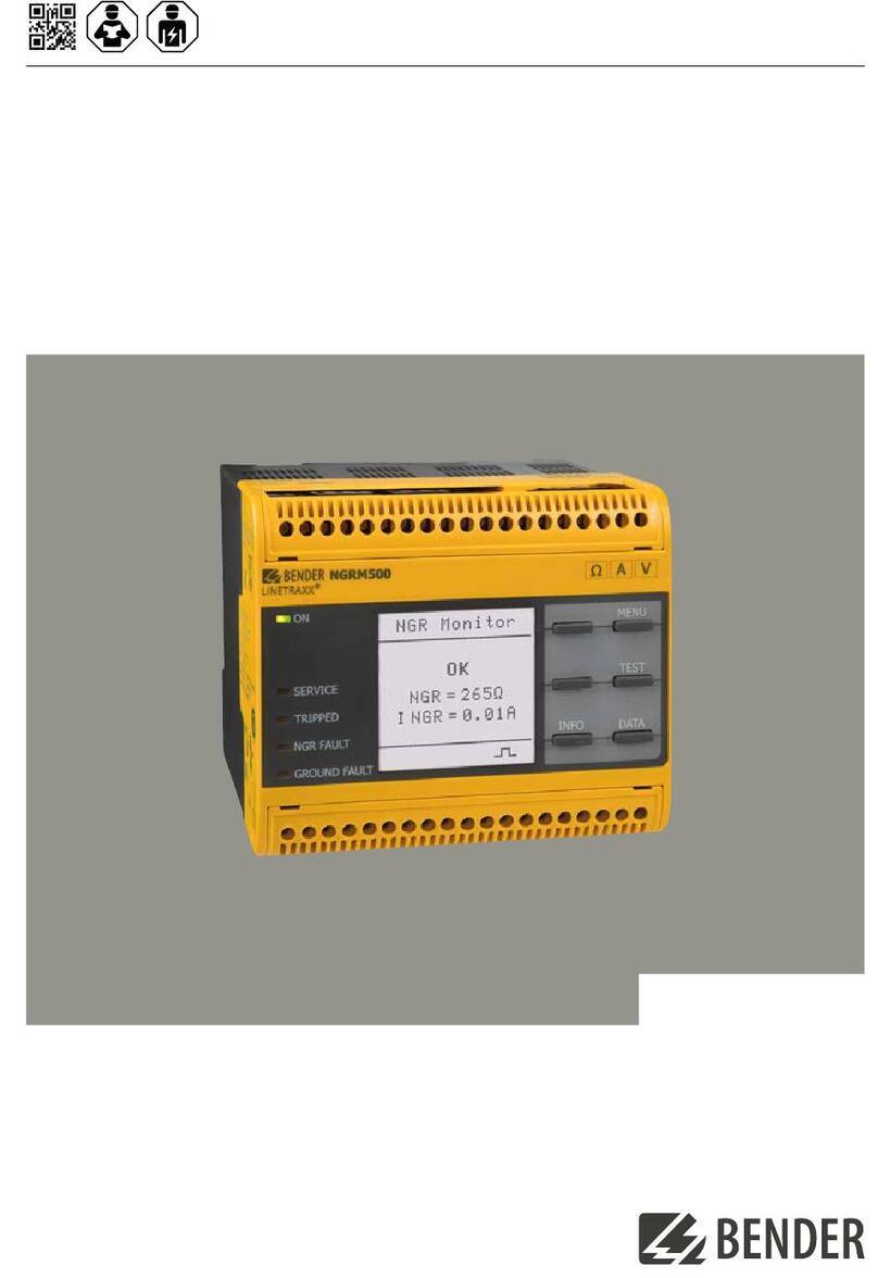
Bender ISOMETER isoES425 User manual


Other manuals for ISOMETER isoES425
3
Table of contents
Other Bender Measuring Instrument manuals
Bender
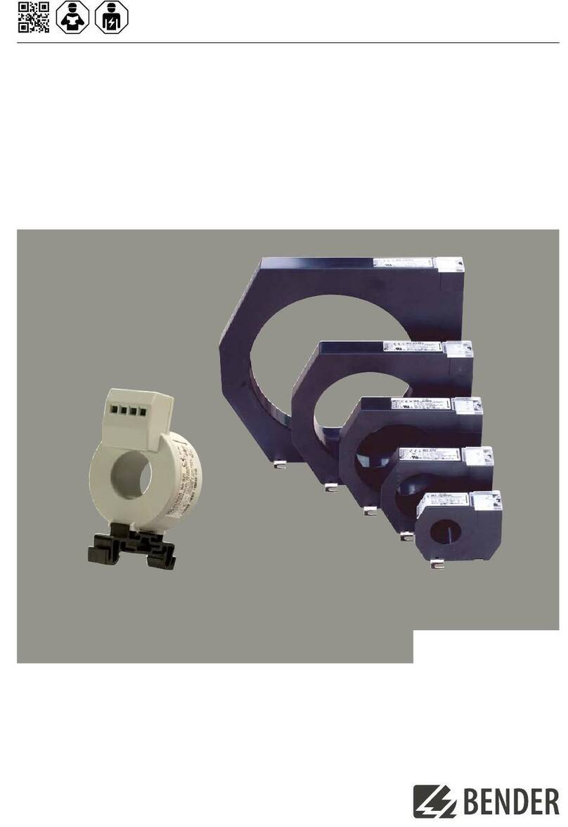
Bender Linetraxx CTUB100 Series User manual
Bender
Bender W0-S20 User manual
Bender
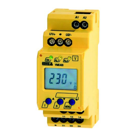
Bender VME420 User manual
Bender
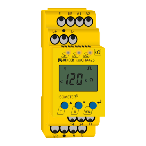
Bender ISOMETER isoCHA425 User manual
Bender
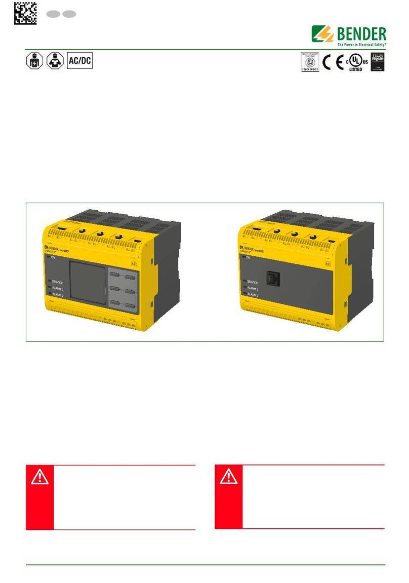
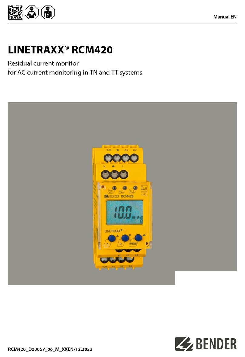
Bender iso685 User manual
Bender
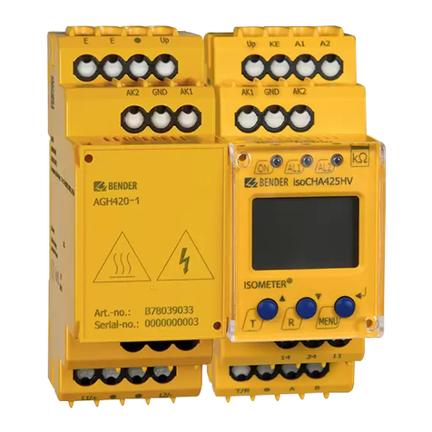
Bender LINETRAXX RCM420 User manual
Bender
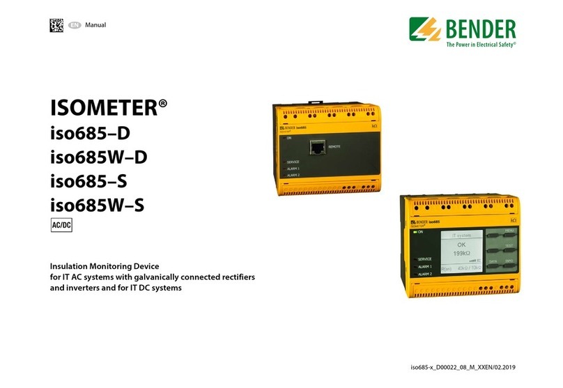
Bender ISOMETER isoCHA425HV User manual
Bender
Bender ISOMETER iso685W-D User manual

Bender
Bender iso1685 Series User manual

Bender
Bender PEM735 User manual
Bender
Bender ISOMETER isoCHA425 User manual
Bender
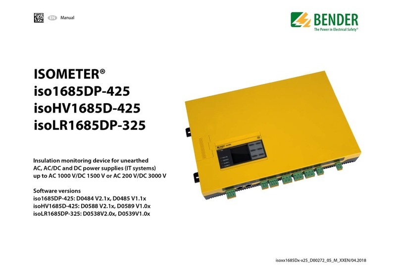
Bender ISOMETER iso1685DP-425 User manual

Bender
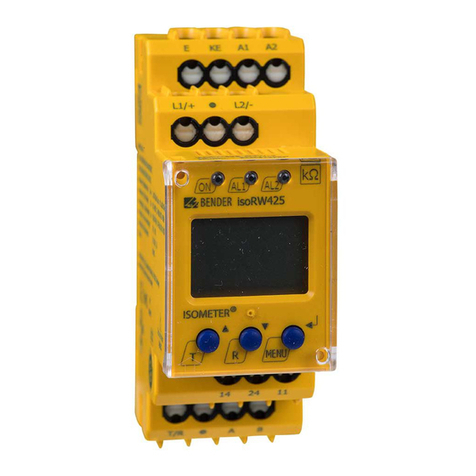
Bender ISOMETER isoCHA425 User manual
Bender
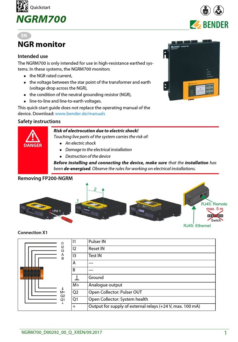
Bender ISOMETER isoRW425 User manual
Bender
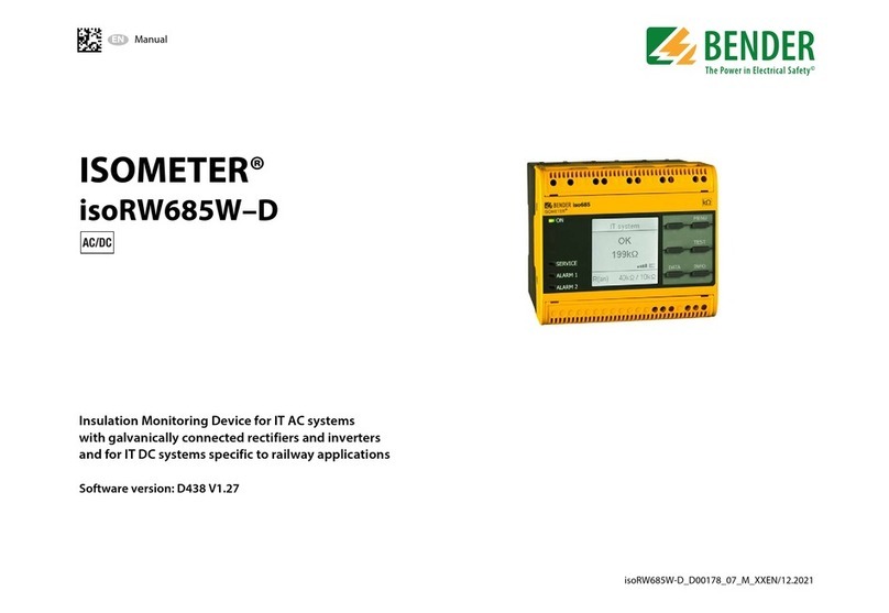
Bender NGRM700 User manual
Bender
Bender ISOMETER isoRW685W-D User manual
Bender
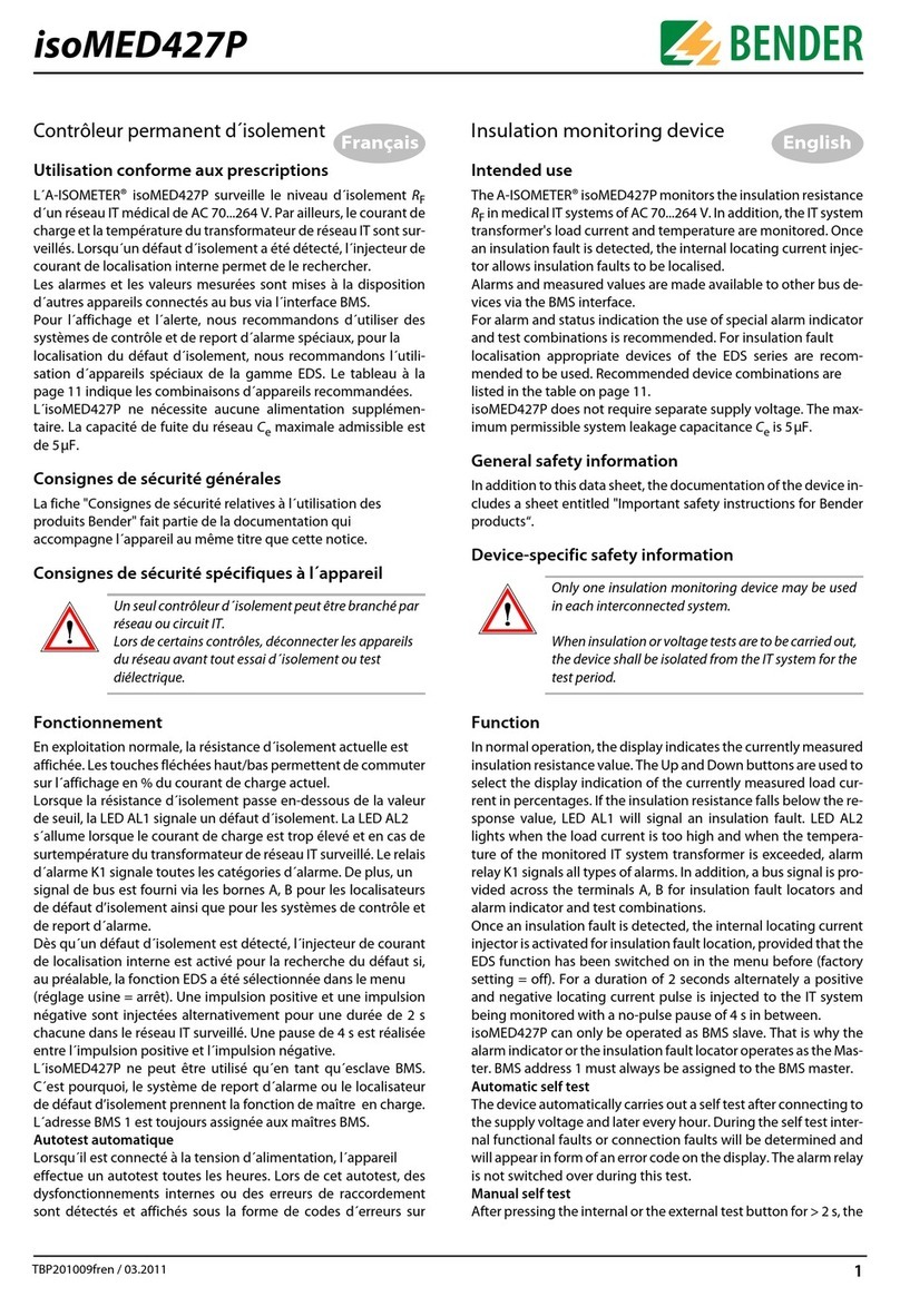
Bender isoMED427P User manual
Bender
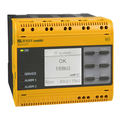
Bender iso685 User manual
Bender
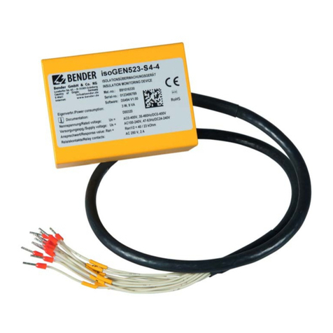
Bender ISOMETER isoGEN523-S4-4 User manual
Bender
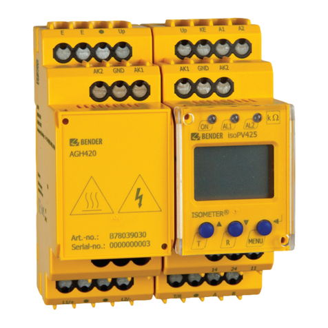
Bender ISOMETER isoPV425 with AGH420 User manual
Popular Measuring Instrument manuals by other brands

Harvia
Harvia sentiotec 260-TH Instructions for use
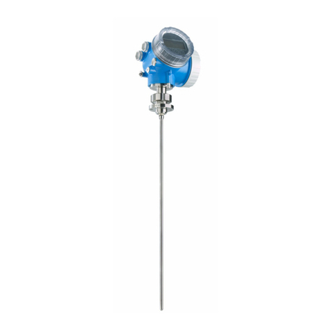
Endress+Hauser
Endress+Hauser Levelflex FMP53 operating instructions
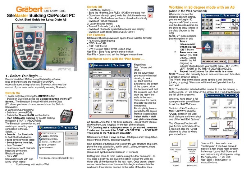
Leica
Leica DISTO A6 quick start guide
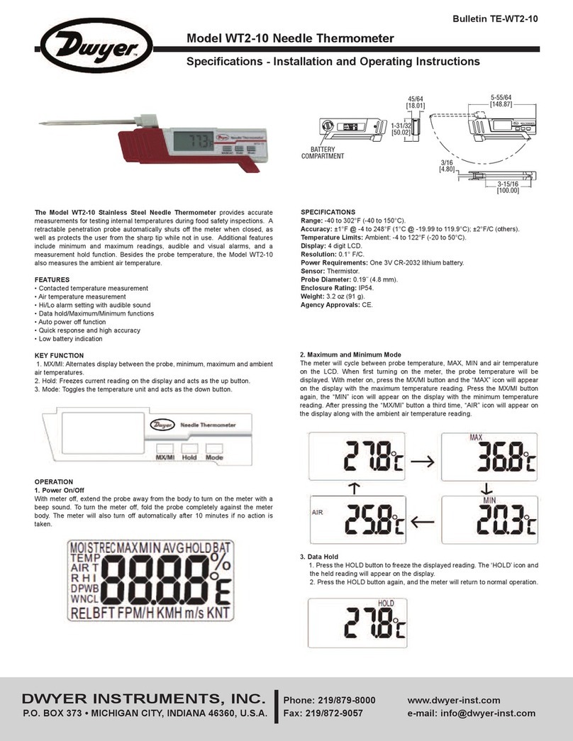
Dwyer Instruments
Dwyer Instruments WT2-10 Specifications-installation and operating instructions

Nidek Medical
Nidek Medical OPD-Scan III Operator's manual
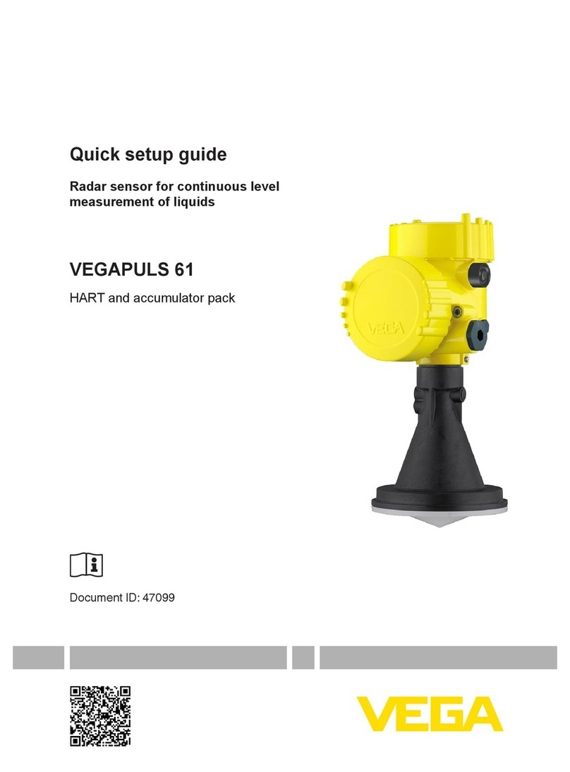
Vega
Vega VEGAPULS 61 Quick setup guide
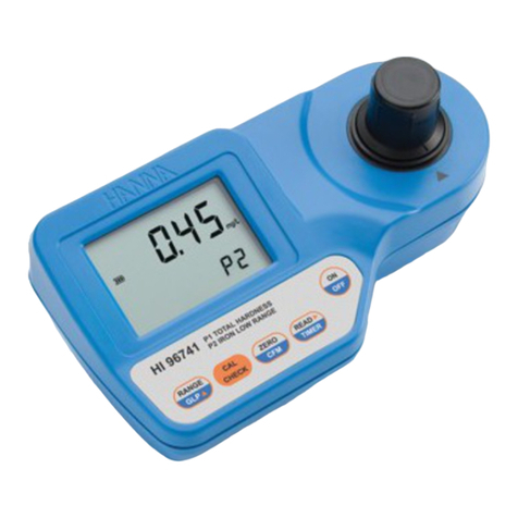
Hanna Instruments
Hanna Instruments HI 96741C instruction manual

Piusi
Piusi MK325 Instructions for installation, use and maintenance manual

HERON
HERON dipper-Temp Operating and maintenance instructions
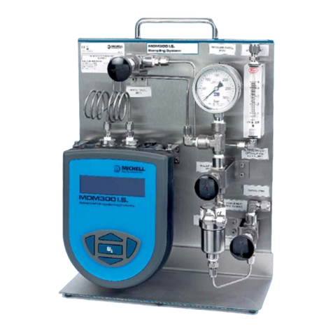
Michell Instruments
Michell Instruments MDM300 I.S. user manual
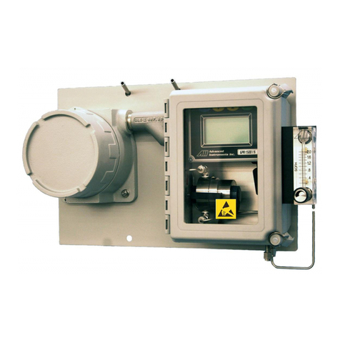
AII
AII GPR-1800 manual

Rosemount
Rosemount 2120 Reference manual

Omnik New Energy Co., Ltd.
Omnik New Energy Co., Ltd. Omniksol-WIFIKIT user manual
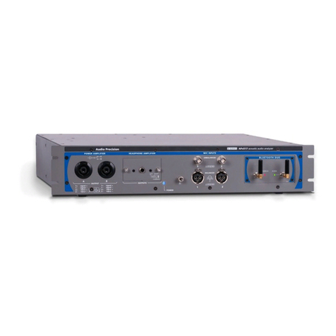
Audio Precision
Audio Precision B Series installation instructions

Siemens Healthcare
Siemens Healthcare DCA Vantage Operator's guide
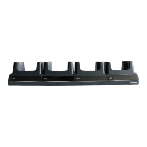
Ecom
Ecom Quad Dock Ethernet user manual

Eastern Energy
Eastern Energy PMS-714 Operation manual

YSI
YSI 3200 Operation manual
