manuals.online logo
Brands
  1. Home
  2. •
  3. Brands
  4. •
  5. Bender
  6. •
  7. Measuring Instrument
  8. •
  9. Bender PEM735 User manual

Bender PEM735 User manual

1
Quick start guide
EN
Power quality analyser
This reference guide does not replace the operating manual!
The manual is available on our Web site www.bender.de
Make sure that the relevant personnel has read this manual and
understood all instructions relating to safety.
1. Safety instructions 2. Intended use
The PEM735 is suitable for
Analysing energy and power
Monitoring the supply voltage quality (Power Quality) in
accordance with DIN EN 50160
Recording relevant energy management data (Energy Man-
agement)
As a compact device for front panel mounting, it can replace ana-
logue indicating instruments. The PEM735 is suitable for 3 and 4-
wire systems and can be used in TN, TT and IT systems. The current
measurement inputs of the PEM are connected via external …/1 A
or …/5 A measuring current transformers. In principle, measure-
ments in medium- and high-voltage systems are carried out via
measurement transformers and voltage transformers. The accuracy
of the active energy metering corresponds to class 0.2 S, which is in
compliance with the DIN EN 62053-22 (VDE 0418 Part 3-22):2003-
11.
3. Scope of delivery
1 PEM735
Safety instructions
Quick start guide
1 Sealing frame with protection level IP54
4. Installing the device
Front-panel mounting (front view, side view, panel cutout)
A front-panel cutout of 138 mm x 138 mm is required for the device.
1. Insert the device through the cutout in the front panel.
2. Insert the two installation clips into the equipment rail from behind.
3. Push the clips towards the front panel and tighten the associated screws by hand.
4. Check the device to ensure that it is firmly installed in the front panel.
Danger of electric shock!
Follow the basic safety rules when working with electricity.
Consider the data on the rated voltage and supply voltage
as specified in the technical data!
DANGER
144
145
125
144
138
16 109
138
20
144
164
138
138
PEM735
PEM735_D00084_01_Q_XXEN/06.2020
2PEM735_D00084_01_Q_XXEN/06.2020
PEM735
5. Connecting the PEM735
Wiring diagram Wiring diagram legend
Connection
1. Connect the device according the wiring diagram. The con-
nections are located on the back of the device. Connect the
PEM735 to the supply voltage (terminals A1/+, A2/-. Connect
terminal " " to the protective conductor.
2. Line protection: A 6 A fuse is recommended for both lines if
being from an IT system.
3. Connection to the RS-485 bus is made via terminals D+, D- and
SH. Up to 32 devices can be connected to the bus. The maxi-
mum cable length for the bus connection of all devices is
1200 m.
6. Connecting the voltage inputs
•l41
•l31
•l11
L3
•l21
NC
l42
I32
I12
l22
L2
L1
NC
N
L4
NC
D+
P2(RS-485)
D-
D+
SH
D-
SH
P1(RS-485)
DI8
DI7
DI6
DI5
DI4
DI3
DI2
DI1
DIC
Power
A2/-
A1/+
RO23
RO43
RO24
RO33
RO34
RO44
RO14
RO13
DO1-
DO1+
DO2-
DO2+
Act Link
P3
10/100M
Ethernet
LED
D+
P2(RS-485)
D-
D+
SH
D-
SH
P1(RS-485)
10/100M
Ethernet
US
DI1
DI5 DI6DI2 DI3 DI4 DI7 DI8 DIC
L1
I11
I12
I21
I22
I31
I32
I41
I42
L2
L3
N
L1 L2 L3 N
DO1+ DO1-
DO2+ DO2-
RO13 RO14
RO23 RO24
RO33 RO34
RO43 RO44
Terminal Description
A1, A2,
Connection to supply voltage, 6 A fuse (when sup-
plied by IT systems, both phase conductors have to
be protected).
DI1…DI6, DIC Digital inputs (24 V)
DO1+, DO1-,
DO2+, DO2- Digital outputs (N/O contacts, 30 V; 50 mA)
RO13/RO14,
RO23/RO24,
RO33/RO34
RO43/RO44
Relay outputs (250 V; 3 A)
I11, I12,
I21, I22,
I31, I32
Connection to the system to be monitored:
The measuring leads should be protected
with appropriate fuses (6 A).
D+, D-, SH RS-485 bus connection
L1, L2, L3, L4, N Measuring voltage inputs: The measuring leads
should be protected with appropriate fuses.
Modbus TCP: Pin assignment
1 Transmit Data +
2 Transmit Data –
3 Receive Data +
4, 5, 7, 8 not used
6 Receive Data –
12345678
Three-phase 4-wire system
(TN, TT, IT system) Three-phase 3-wire system Connection via voltage transformers
The PEM can be used in three-phase 4-wire
systems, independent of the type of distri-
bution system (TN, TT, IT system).
The PEM can be used in three-phase 3-wire
systems.
The measuring device can be used in medi-
um- and high-voltage systems if coupled via
voltage transformers.
The transmission ratio can be adjusted in
the PEM735 (primary and secondary side
separately).
L1 L2 L3 N
PEM
Ri
AC 400/230 V
AC 690/400 V
L1 L2 L3
PEM
Ri
AC 400 V
N
L1 L2 L3
PEM
Ri
AC 690 V
N
L1 L2 L3 N
PEM
R
i
LV / MV / HV
3
PEM735_D00084_01_Q_XXEN/06.2020
PEM735
7. Commissioning the device 8. Start
Check for proper connection
Observe the relevant standards and regulations for installation and
connection as well as the operating manual of the respective de-
vice.
Before switching on:
consider the following:
1. Does the connected supply voltage correspond to the infor-
mation on the nameplate?
2. Are you sure that the nominal insulation voltage of the meas-
uring current transformer has not been exceeded?
3. Does the measuring current transformer's maximum current
correspond to the nameplate information of the connected
device?
After switching on:
proceed as follows:
1. Connect the supply voltage.
2. Set the bus address/IP address.
3. Select wye or delta connection.
4. Set the CT transformation ratio (for each channel).
5. Change the measuring current transformer's counting direc-
tion, if required.
6. Set the nominal voltage (line-to-line voltage ULL, secondary
voltage for voltage transformers)
Basic parameters, interfaces or calculation types can be specified in
the "Settings" menu.
The following diagram will help you to familiarise yourself with the
menu:
9. Display and operating controls
Display and operating control legend
A correct password must be entered before parameter
changes are allowed. (factory setting: 0000)
Current
Power Quality >
Voltage
Waveform
Harmonics
Phasor Diagram
Flicker
EN50160 >
U Sum, I Sum, L1, L2, L3
U1, U2, U3, U4, I1, I2, I3, I4
ULn, ULL
I1, I2, I3, I4, Iavg
ENTER
>
>
>
>
>
>
>
>
>
Device buttons
0
2
4
6
8
10
Main Menu
Power & Energy
System
Energy, Sum, L1, L2, L3
DI1...8, DO1...2, RO1...4
SOE
PQLog
Settings > Info
Basic
Ethernet
COM
Advanced
Time
Events >
>
>
>
>
ENTER
ENTER
Metering U, I, RMS, Fundamental
>
ENTER
Others
LEDs kWh, kvarh
Button
sENTER ESC
Back;
Submenu: scroll;
Selection left side
Main menu: move
upwards in the menu;
Increase number/selec-
tion
Main menu: move down
in the menu;
Decrease number/
selection
Select menu item;
Submenu: scroll;
Selection right side
Ok;
Enter submenu;
"Freeze" waveform
recorder; depending on
the submenu further
function (see display)
Leave submenu item;
"Unfreeze" waveform
recorder"; depending
on the submenu further
function (see display)
4PEM735_D00084_01_Q_XXEN/06.2020
PEM735
All rights reserved. Reprinting only with permission of the
publisher. Subject to change!
© Bender GmbH & Co. KG
Photos: Bender archives.
E-Mail: [email protected]
www.bender.de
Bender GmbH & Co. KG
Londorfer Str. 65 • 35305 Grünberg • Germany
PO Box 1161 • 35301 Grünberg • Germany
Tel.: +49 6401 807-0
Fax: +49 6401 807-259
10. Data display via buttons 11. Data display via communication inter-
face/Web interface
The evaluation of a number of measured values can be accessed
directly on the device using the device buttons, without having to
use the communications interface. Thus it is possible to show the
phasor diagram, reports, flicker, currents and voltages, current
waveforms, harmonics, … directly on the display.
All measuring values can be obtained via the communications
interface. Details concerning the Modbus register assignment can
be found in the operating manual.

Other manuals for PEM735

3

Other Bender Measuring Instrument manuals
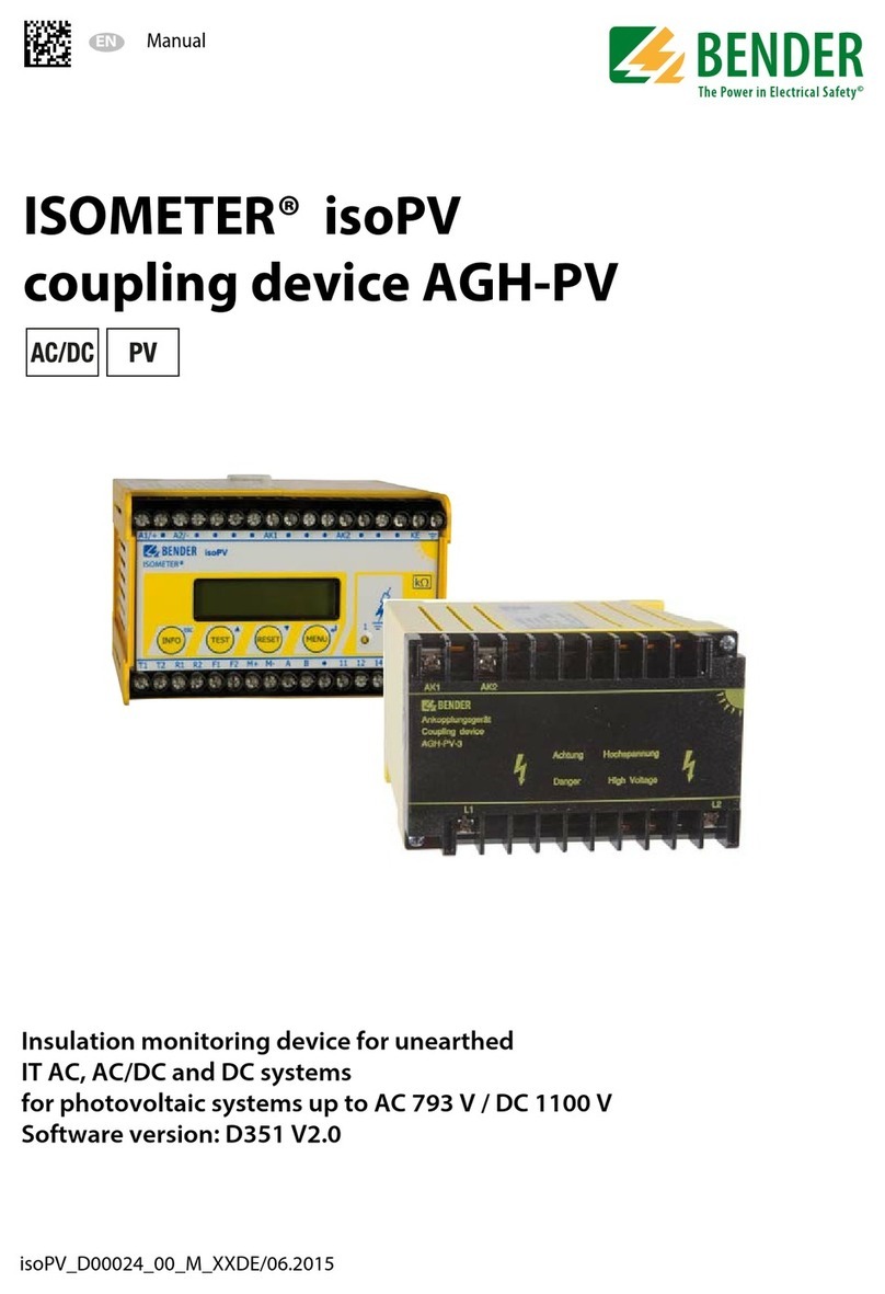
Bender ISOMETER isoPV1685RTU User manual

Bender

Bender ISOMETER isoPV1685RTU User manual

Bender ISOMETER isoRW685W-D-B User manual

Bender

Bender ISOMETER isoRW685W-D-B User manual

Bender ISOMETER isoUG425 User manual

Bender

Bender ISOMETER isoUG425 User manual
Bender VMD423H User manual

Bender

Bender VMD423H User manual

Bender RCMB330 User manual

Bender

Bender RCMB330 User manual

Bender PEM330 User manual

Bender

Bender PEM330 User manual

Bender NGRM700 User manual

Bender

Bender NGRM700 User manual
Bender ISOMETER IRDH375 User manual

Bender

Bender ISOMETER IRDH375 User manual

Bender NGRM700 User manual

Bender

Bender NGRM700 User manual

Bender ISOMETER isoES425 User manual

Bender

Bender ISOMETER isoES425 User manual

Bender ISOMETER isoNAV685-D User manual

Bender

Bender ISOMETER isoNAV685-D User manual

Bender A-ISOMETER IR1570 Series User manual

Bender

Bender A-ISOMETER IR1570 Series User manual

Bender ISOMETER isoHV525-M4-4 User manual

Bender

Bender ISOMETER isoHV525-M4-4 User manual

Bender VMD423-D-1 User manual

Bender

Bender VMD423-D-1 User manual

Bender COM465IP User manual

Bender

Bender COM465IP User manual

Bender RCMA423AS User manual

Bender

Bender RCMA423AS User manual

Bender EDS3090 User manual

Bender

Bender EDS3090 User manual

Bender COMTRAXX COM465ID User manual

Bender

Bender COMTRAXX COM465ID User manual

Bender NGRM500 User manual

Bender

Bender NGRM500 User manual

Bender isoMED427 User manual

Bender

Bender isoMED427 User manual

Bender ISOMETER iso415R User manual

Bender

Bender ISOMETER iso415R User manual

Bender MRCDB423 Series User manual

Bender

Bender MRCDB423 Series User manual

Bender ISOMETER IR425-D4M 1C User manual

Bender

Bender ISOMETER IR425-D4M 1C User manual

Bender ISOMETER iso1685DP-425 User manual

Bender

Bender ISOMETER iso1685DP-425 User manual

Popular Measuring Instrument manuals by other brands

Lumantek SKY BAND Upgrade manual

Lumantek

Lumantek SKY BAND Upgrade manual

dji Aeroscope Mobile user guide

dji

dji Aeroscope Mobile user guide

Apera Instruments LabSen 753 user manual

Apera Instruments

Apera Instruments LabSen 753 user manual

Keysight N9010B Service guide

Keysight

Keysight N9010B Service guide

DigiVac Bullseye Precision Gauge Pirani user manual

DigiVac

DigiVac Bullseye Precision Gauge Pirani user manual

Hach POLYMETRON 8810 Basic user manual

Hach

Hach POLYMETRON 8810 Basic user manual

socomec DIRIS A40 operating instructions

socomec

socomec DIRIS A40 operating instructions

ABB Sensyflow FMT700-P Operating	 instruction

ABB

ABB Sensyflow FMT700-P Operating instruction

Medical Freezer GPRS operating manual

Medical Freezer

Medical Freezer GPRS operating manual

CSX P330A instructions

CSX

CSX P330A instructions

Elma Laser X360 Series manual

Elma

Elma Laser X360 Series manual

Mag-ic Probe WiFi manual

Mag-ic Probe

Mag-ic Probe WiFi manual

McCrometer Dura Mag Quick start installation guide

McCrometer

McCrometer Dura Mag Quick start installation guide

Cropico DO6 Handbook

Cropico

Cropico DO6 Handbook

AR DC6380M2 Operating and service manual

AR

AR DC6380M2 Operating and service manual

Fowler Xtra-Value Cal Operating instructions and parts manual

Fowler

Fowler Xtra-Value Cal Operating instructions and parts manual

AR DC7281A Operating and service manual

AR

AR DC7281A Operating and service manual

HBK C5 Mounting instructions

HBK

HBK C5 Mounting instructions

manuals.online logo
manuals.online logoBrands
  • About & Mission
  • Contact us
  • Privacy Policy
  • Terms and Conditions

Copyright 2025 Manuals.Online. All Rights Reserved.