manuals.online logo
Brands
  1. Home
  2. •
  3. Brands
  4. •
  5. Bender
  6. •
  7. Measuring Instrument
  8. •
  9. Bender VMD423H User manual

Bender VMD423H User manual

Power in electrical safety
Operating Manual
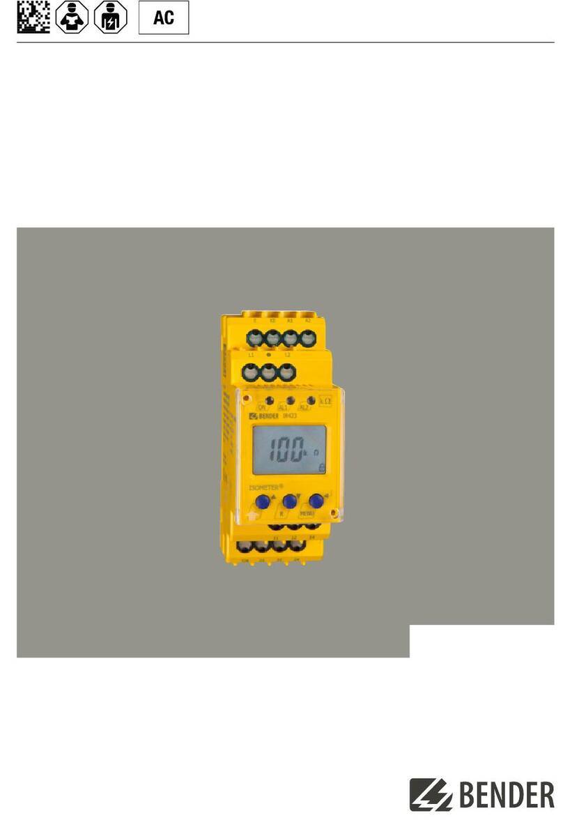
VMD423H
Voltage and frequency monitor
for monitoring of 3(N)AC systems up to 0...500 V
for undervoltage and overvoltage and under and overfrequency
Software version: D345 V3.1x
TGH1445en/04.2011
Dipl.-Ing. W. Bender GmbH & Co. KG
Londorfer Str. 65 • 35305 Grünberg • Germany
Postfach 1161 • 35301 Grünberg • Germany
Tel.: +49 6401 807-0
Fax: +49 6401 807-259
E-Mail: [email protected]om
Web: http://www.bender-de.com
©Dipl.-Ing. W. Bender GmbH & Co. KG
All rights reserved.
Reprinting only with permission
of the publisher.
Subject to change!
Table of Contents
3
TGH1445en/04.2011
1. How to use this documentation effectively ............................................... 5
1.1 How to use this manual ................................................................................. 5
2. Safety .................................................................................................................. 7
2.1 General ................................................................................................................. 7
2.2 Intended use ...................................................................................................... 7
2.3 Skilled person .................................................................................................... 7
2.4 Safety information on work activities on electrical installations .. 8
3. Function ............................................................................................................. 9
3.1 Device features ................................................................................................. 9
3.2 Function ............................................................................................................ 10
3.2.1 Calculating the average value of overvoltage .................................... 10
3.2.2 Automatic self test ........................................................................................ 10
3.2.3 Manual self test .............................................................................................. 10
3.2.4 Functional faults ............................................................................................ 11
3.2.5 Fault memory ................................................................................................. 11
3.2.6 Assigning alarm categories to alarm relays K1/K2 ............................ 11
3.2.7 Time delays t, ton and toff ........................................................................... 11
3.2.8 Start-up delay t ............................................................................................... 11
3.2.9 Response delay ton ....................................................................................... 11
3.2.10 Delay on release toff ...................................................................................... 12
3.2.11 Password protection (on, OFF) ................................................................. 12
3.2.12 Factory setting FAC ...................................................................................... 12
3.2.13 Erasable history memory ............................................................................ 12
3.2.14 Alarm LEDs show which relay is in the alarm state ........................... 12
3.2.15 Starting a device using a simulated alarm S.AL ................................. 12
4. Installation, connection and commissioning ........................................... 15
Table of Contents
4TGH1445en/04.2011
4.1 Installing the device ..................................................................................... 16
4.1.1 DIN rail mounting: ......................................................................................... 16
4.1.2 Screw mounting ............................................................................................ 16
4.2 Wiring of the device ..................................................................................... 17
4.3 Commissioning / factory setting ............................................................. 19
5. Operation and setting .................................................................................. 21
5.1 Getting to know the user interface ......................................................... 21
5.2 Understanding standard display indications ...................................... 23
5.3 Getting to know keys and key functions .............................................. 24
5.4 Querying values ............................................................................................. 25
5.5 Starting the self test manually .................................................................. 27
5.6 Clearing the fault memory ......................................................................... 27
5.7 Calling up or leaving the menu ................................................................ 27
5.8 Carrying out settings in the menu .......................................................... 27
5.8.1 Password protection .................................................................................... 27
5.8.2 Selecting menu items .................................................................................. 29
5.8.3 Carrying out settings in the menu item AL .......................................... 31
5.8.4 Carrying out settings in the menu item out ........................................ 35
5.8.5 Carrying out settings in the menu item t ............................................. 41
5.8.6 Carrying out settings in the menu item SEt ......................................... 42
5.8.7 Querying information in menu item INF .............................................. 44
5.8.8 Querying and clearing fault memory in the menu item HIS ......... 45
6. Technical data ................................................................................................ 47
6.1 Data in tabular form ..................................................................................... 47
6.2 Standards, approvals and certifications ................................................ 50
6.3 Ordering information ................................................................................... 51
6.4 Label for modified versions ....................................................................... 51
INDEX .................................................................................................................... 53
5
TGH1445en/04.2011
1. How to use this documentation effectively
1.1 How to use this manual
This operating manual is designed for skilled persons working in electrical en-
gineering and electronics and must always be kept in an easily accessible lo-
cation near to the equipment.
In order to make it easier for you to find specific text passages or references in
this manual and for reasons of comprehensibility, important information is
emphasised by symbols. The meaning of these symbols is explained below:
Information calling attention to hazards are marked
with this warning symbol.
Information intended to assist the user to make optimum
use of the product are marked with the Info symbol.
How to use this documentation effectively
6TGH1445en/04.2011
7
TGH1445en/04.2011
2. Safety
2.1 General
In addition to this manual, the documentation of the device includes a docu-
ment entitled "Important safety instructions for Bender products“.
2.2 Intended use
The voltage monitor VMD423H is used in 3(N)AC systems in accordance with
VDE V 0126-1-1 for undervoltage, overvoltage, underfrequency and overfre-
quency monitoring. The device is suitable for the nominal voltage range Un=
70...500 V in the frequency range 40...65 Hz.
The device is internally supplied by the nominal voltage to be monitored.
2.3 Skilled person
Only electrically skilled persons are authorised to install and commission this
device. Electrically skilled persons are those who have the relevant education,
knowledge and experience, as well as knowledge of the relevant safety stand-
ards and who are able to perceive risks and to avoid hazards which electricity
can create when work activities are carried out on electrical installations. The
electrically skilled person is specially trained for carrying out work activities in
his specific working environment and has a thorough knowledge of the rele-
vant standards and regulations.
In Germany, an electrically skilled person must meet the requirements of the
accident prevention regulation BGV A3. In other countries the applicable reg-
ulations have to be observed and followed.
Safety
8TGH1445en/04.2011
2.4 Safety information on work activities on electrical in-
stallations
Touching live parts will cause danger of electric shock
with fatal consequences! All work activities on electrical
installations as well as installation activities, commis-
sioning activities and work activities with the device in
operation may only be carried out by electrically skilled
persons!
Danger of electric shock!
Unprofessional work activities on electrical installations
may result in a threat of danger to life and limb!
9
TGH1445en/04.2011
3. Function
3.1 Device features
 The VMD423H is internally supplied by the nominal voltage Un
 Monitoring for undervoltage and overvoltage and underfrequency and
overfrequency in 3(N)AC systems of AC 70...500 V / 70...288 V
 Monitoring of overvoltage U2 by average determination of the latest
10-minute measuring interval
 Asymmetry, phase failure and phase sequence monitoring
 Start-up delay, response delay and delay on release
 Adjustable switching hysteresis for the voltage to be monitored
 r.m.s. value measurement AC + DC
 Digital measured value display via multi-functional LC display
 LEDs: Power On, Alarm1 and Alarm2
 Fault memory for the operating value
 Cyclical self monitoring
 Internal test/reset button
 Two separate alarm relays (one changeover contact each)
 N/C or N/O operation and fault memory behaviour selectable
 Password protection for device settings
 Sealable transparent cover
 Available with screw-type or push-wire terminals
 Start-up of the device with or without simulated alarm message
Function
10 TGH1445en/04.2011
3.2 Function
Once the nominal voltage is applied, the start-up delay plus response delay (t
+ ton1/2) begins. Throughout this time, an alarm is output via alarm LEDs and
relays. Measured voltage and frequency values being changed during this
start-up period t do not influence the alarm LEDs and the state of the alarm re-
lays.
The devices utilise several separately adjustable measuring channels (over-
voltage/undervoltage, overfrequency/underfrequency). When the measured
value exceeds or falls below the response value, the alarm relays switch and
the alarm LEDs light up. When the measured value exceeds or falls below the
release value (response value plus hysteresis) after the alarm relays have
switched, the selected release delay toff begins. When toff has elapsed, the
alarm relays switch back to their initial position. With the fault memory acti-
vated, the alarm relays do not change their actual state until the reset button
R is pressed. Also in the event of complete power failure of the system being
monitored, the delay times are effective during the energy backup discharg-
ing time.
3.2.1 Calculating the average value of overvoltage
The overvoltage U2 is determined by calculating an average value of the last
10-minute measuring interval.
Always the highest average value U2 of each of the three voltages monitored
between L1-N, L2-N, L3-N will be indicated.
3.2.2 Automatic self test
The device automatically carries out a self test after connection to the system
to be monitored and later every hour. During the self test internal functional
faults are detected and will appear in form of an error code on the display. The
alarm relays are not tested during this time.
3.2.3 Manual self test
Pressing the test button for > 1.5 s causes the device to carry out a self test
where the internal functional errors are determined and shown on the display
as error codes. The alarm relays are not tested during this time.
Function
11
TGH1445en/04.2011
While the test button T is pressed and held down, all device-related display el-
ements appear on the display.
3.2.4 Functional faults
If an internal malfunction occurs, all three LEDs flash. An error code will appear
on the display (E01...E32). In such a case please contact the Bender Service.
3.2.5 Fault memory
The fault memory can be activated, deactivated or can be set to continuous
mode (con). If the fault memory is set to "con“ mode, the alarm parameters re-
main stored even on failure of the supply voltage.
3.2.6 Assigning alarm categories to alarm relays K1/K2
Different alarm categories can be assigned to the alarm relays K1/K2 via the
menu "out". For details about alarm category assignment to the respective re-
lays refer to the submenu out description on page 37.
3.2.7 Time delays t, ton and toff
The times t, ton and toff described in the following delay the output of alarms
via the LEDs and relays.
3.2.8 Start-up delay t
Once the supply voltage Ushas been switched on, the alarm indication is de-
layed by the preset time t (0...300 s).
3.2.9 Response delay ton
When the value drops below or exceeds the response value, the voltage mon-
itor requires the response time tan until the alarm is activated.
A preset response delay ton (0...300 s) adds up to the device-related operating
time tae and delays alarm signalling (total delay time tan = tae + ton).
If the fault no longer exists during the response delay, the alarm signal drops
out.
Function
12 TGH1445en/04.2011
3.2.10 Delay on release toff
If the alarm no longer exists during the response delay and the fault memory
is deactivated, the alarm LEDs will go out and the alarm relays switch back to
their initial position. The delay on release (0...300 s) serves to maintain the
alarm state signal for the set duration.
3.2.11 Password protection (on, OFF)
By default, the password protection is activated (on). Settings are only possi-
ble after entering the correct password (0...999). If you cannot operate your
device because you cannot remember your password, please contact in-
[email protected].
3.2.12 Factory setting FAC
After activating the factory setting, all settings previously changed are reset to
delivery status.
3.2.13 Erasable history memory
The first alarm value to occur is saved in this memory. Subsequent alarms do
not overwrite this "old“ value. The memory can be cleared using the Clr key in
the menu HiS. This function is not password protected.
3.2.14 Alarm LEDs show which relay is in the alarm state
When the menu item LEd is activated, the alarm LED AL1 indicates that
K1 is in the alarm state. When AL2 lights up, K2 is in the alarm state. An alarm
relay cannot switch to the alarm state unless an alarm category has been as-
signed to it.
When the menu item LEd is deactivated, AL1 signals overvoltage, AL2
signals undervoltage, both LEDs AL1 and AL2 light up in case of frequency
alarm.
3.2.15 Starting a device using a simulated alarm S.AL
If the menu item S.AL has been activated in the out menu, K1 resp. K2 switches
back to the alarm state once the nominal voltage is applied. This alarm state
is maintained for the set duration t + ton1. Once this time has elapsed, K1 resp.
Function
13
TGH1445en/04.2011
K2 switches back to the initial position provided that no fault is detected at the
measuring input.
The following diagrams show the effect of a fault during a simulated alarm.
Faults at the measuring input and the resulting condition of the alarm relay K1
(K2) are shown as a hatched area.
The fault for K1 shown in the time diagram below, by way of example, has
started during the S.AL phase:
The fault for K1 shown in the time diagram below, by way of example, started
when the S.AL phase has elapsed:
t
on1
t
t
on1
S.AL
U
F
U
N
K1
t
on1
t
t
on1
S.AL
U
F
U
N
K1
Function
14 TGH1445en/04.2011
15
TGH1445en/04.2011
4. Installation, connection and commissioning
Danger of electric shock! Make sure that the installation
area is disconnected from any electrical source before
starting installation works and that the nominal voltage
and supply voltage specified in the relevant data sheet
are observed!
Installation, connection and commissioning
16 TGH1445en/04.2011
4.1 Installing the device
Fig. 4.1: Dimension diagram and drawing for screw fixing
4.1.1 DIN rail mounting:
1. Snap the rear mounting clip of the device into place in such a way that
a safe and tight fit is ensured.
4.1.2 Screw mounting
1. Use a tool to move the rear mounting clips (a second mounting clip
required, see ordering information) to a position that it projects
beyond the enclosure.
2. Fix the device using two M4 screws.
Zubehör/
Accessory
100 mm
116 mm
2
2
Installation, connection and commissioning
17
TGH1445en/04.2011
4.2 Wiring of the device
Connect the device according the wiring diagram.
Fig. 4.2: Wiring diagram
1
2
3
Connect the conductor to the push-wire ter-
minals according to the drawing.
Terminal Connections
L1, L2, L3, (N) Connection to the sys-
tem to be monitored
11, 12, 14 Alarm relay K1
21, 22, 24 Alarm relay K2
Installation, connection and commissioning
18 TGH1445en/04.2011
Example: Application of a photovoltaic system encountered in practice
Fig. 4.3: Application of an VMD423-D-2 in a photovoltaic system.
Connect the terminals L1/L2/L3 of the VMD423H always to the supply side of
the system to be monitored (but not to the inverter side of the disconnecting
relay).
VMD423H
A2
426
A1
135
=
~
Installation, connection and commissioning
19
TGH1445en/04.2011
4.3 Commissioning / factory setting
Material damage by improper connection of the device!
Prior to commissioning make sure that the device is
properly connected!
Undervoltage < U:
Overvoltage > U1:
Overvoltage > U2 (10 min.):
Hysteresis U:
Underfrequency < Hz
Overfrequency > Hz
Hysteresis frequency (Hys Hz):
Fault memory M:
Operating principle K1
(< U, > U1, Asy, < f, > f, S.AL):
Operating principle K2
(Err, < U, > U1, > U2, Asy,
< f, > f, PHS, S.AL):
AL1/AL2 indicate the alarm
state of K1/K2 (LEd):
Alarm to K1/K2 (S.AL) when
the device is started:
Asymmetry:
Phase sequence monitoring:
Start-up delay:
Response delay:
Delay on release:
Method of measurement:
Password:
184 V
264 V
253 V
5 %
47.5 Hz
50.2 Hz
0.1 Hz
OFF
N/C operation (n.c.)
OFF
on
30 %
R, on
t = 30 s
ton1 = 0,1 s
ton2 = 0,1 s
toff = 30 s
3n (phase voltage measurement)
126, On
Installation, connection and commissioning
20 TGH1445en/04.2011

This manual suits for next models

3

Other Bender Measuring Instrument manuals

Bender A-ISOMETER IR425 User manual

Bender

Bender A-ISOMETER IR425 User manual

Bender ISOMETER isoLR275 User manual

Bender

Bender ISOMETER isoLR275 User manual

Bender iso685 User manual

Bender

Bender iso685 User manual

Bender ISOMETER isoPV425 with AGH420 User manual

Bender

Bender ISOMETER isoPV425 with AGH420 User manual

Bender ISOMETER IR425-D4 User manual

Bender

Bender ISOMETER IR425-D4 User manual

Bender ISOMETER isoHV425 User manual

Bender

Bender ISOMETER isoHV425 User manual

Bender RCMB423EM User manual

Bender

Bender RCMB423EM User manual

Bender ISOMETER IRDH575 User manual

Bender

Bender ISOMETER IRDH575 User manual

Bender COMTRAXX MK2430 User manual

Bender

Bender COMTRAXX MK2430 User manual

Bender ISOMETER isoRW685W-D User manual

Bender

Bender ISOMETER isoRW685W-D User manual

Bender LINETRAXX CTBC series User manual

Bender

Bender LINETRAXX CTBC series User manual

Bender A-ISOMETER IR420-D4 User manual

Bender

Bender A-ISOMETER IR420-D4 User manual

Bender ISOMETER isoPV425 with AGH420 User manual

Bender

Bender ISOMETER isoPV425 with AGH420 User manual

Bender CMD420-DM User manual

Bender

Bender CMD420-DM User manual

Bender MK2418C User manual

Bender

Bender MK2418C User manual

Bender ISOMETER isoGEN423 User manual

Bender

Bender ISOMETER isoGEN423 User manual

Bender ISOMETER isoUG425 User manual

Bender

Bender ISOMETER isoUG425 User manual

Bender LINETRAXX CTBS25 User manual

Bender

Bender LINETRAXX CTBS25 User manual

Bender ISOMETER isoHR685W-x-I-B User manual

Bender

Bender ISOMETER isoHR685W-x-I-B User manual

Bender RCMA423 User manual

Bender

Bender RCMA423 User manual

Bender ISOMETER isoGEN423-D4-4 User manual

Bender

Bender ISOMETER isoGEN423-D4-4 User manual

Bender RCMA423 User manual

Bender

Bender RCMA423 User manual

Bender ISOMETER isoRW425 User manual

Bender

Bender ISOMETER isoRW425 User manual

Bender ISOMETER iso1685DP-425 User manual

Bender

Bender ISOMETER iso1685DP-425 User manual

Popular Measuring Instrument manuals by other brands

Tenmars ST-502 user manual

Tenmars

Tenmars ST-502 user manual

U-Tron U-6860-100 manual

U-Tron

U-Tron U-6860-100 manual

Spectra Precision LL100N user guide

Spectra Precision

Spectra Precision LL100N user guide

Signet 3-2537-1C-P0 manual

Signet

Signet 3-2537-1C-P0 manual

QEED QC-POWER-T-485 user manual

QEED

QEED QC-POWER-T-485 user manual

PerAlert FW 25-50 Installation and operation manual

PerAlert

PerAlert FW 25-50 Installation and operation manual

Brainstorm Electronics DCD-8 Operation manual

Brainstorm Electronics

Brainstorm Electronics DCD-8 Operation manual

Innerspec ROLLMATE installation instructions

Innerspec

Innerspec ROLLMATE installation instructions

Auxilab MGM039 user manual

Auxilab

Auxilab MGM039 user manual

LI-COR LI-250 instruction manual

LI-COR

LI-COR LI-250 instruction manual

Elvaco CMi6140 user manual

Elvaco

Elvaco CMi6140 user manual

Bosch Atino manual

Bosch

Bosch Atino manual

LANDTEC FPM-2680 quick start guide

LANDTEC

LANDTEC FPM-2680 quick start guide

OHAUS MB35 instruction manual

OHAUS

OHAUS MB35 instruction manual

Deyi TC-8200 manual

Deyi

Deyi TC-8200 manual

TriBrer AOP110 user manual

TriBrer

TriBrer AOP110 user manual

SIXTOL SX3010 Instructions for use

SIXTOL

SIXTOL SX3010 Instructions for use

Shanghai Sunny Hengping Scientific Instrument Co., Ltd UV2000 instruction manual

Shanghai Sunny Hengping Scientific Instrument Co., Ltd

Shanghai Sunny Hengping Scientific Instrument Co., Ltd UV2000 instruction manual

manuals.online logo
manuals.online logoBrands
  • About & Mission
  • Contact us
  • Privacy Policy
  • Terms and Conditions

Copyright 2025 Manuals.Online. All Rights Reserved.