manuals.online logo
Brands
  1. Home
  2. •
  3. Brands
  4. •
  5. BENDIX
  6. •
  7. Air Compressor
  8. •
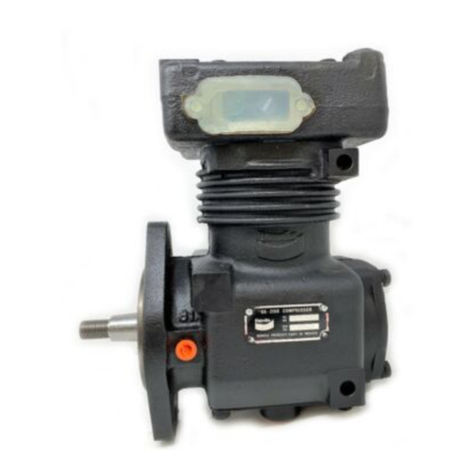
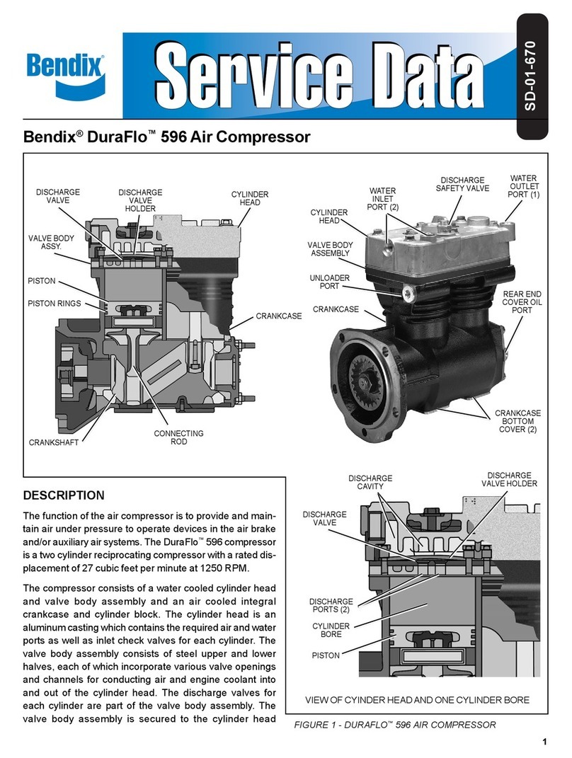
  9. BENDIX DURAFLO 596 COMPRESSOR User manual

BENDIX DURAFLO 596 COMPRESSOR User manual

1
1
2
3
4
5
13 x
85mm
Head Bolt
Washer
8
12
11
9
7
10
Cylinder
Head & Valve
Body Assy.
6
Cylinder
Block
Slotted Plunger
Guide Pin Opening
Pivot Arm
Stud Slots
BENDIX®DURAFLO 596™COMPRESSOR UNLOADER MAINTENANCE KIT
GENERAL
Depending upon the location of the compressor on the
vehicle and ease of access, this kit may be installed without
complete removal of the compressor. All kit components
and their location in the head are shown in Figure 1 above.
Figure 1 –Bendix®DuraFlo 596™Unloader Maintenance Kit Contents
Water
Outlet
(Tap Here
w/Mallet)
Kit Contents
Item No. Description Qty.
1 Sliding Inlet Valve 2
2Pivot Arm 2
3 Pivot Stud 2
4 Guide Pin (Long) 2
5 Guide Pin (Short) 2
6 Gasket 1
7 Plug (Metric & US) 2
8 O-Ring 2
9 Unloader Plunger 2
10 O-Ring 2
11 Split Ring 2
12 Spring 2
13 Lubricant 1
13
2
COMPRESSOR REMOVAL
These instructions are general and are intended to be a guide.
In some cases additional preparations and precautions are
necessary. In all cases follow the instructions contained in
the vehicle maintenance manual in lieu of the instructions,
precautions, and procedures presented here.
1. Block the wheels of the vehicle and drain the air
pressure from all the reservoirs in the system.
2. Drain the engine cooling system and the cylinder head
of the compressor. Identify and disconnect all air, water,
and oil lines leading to the compressor.
3. Remove as much road dirt and grease from the exterior
of the compressor as possible.
Note: If the compressor is not being removed, stop here
and proceed to PREPARATION FOR DISASSEMBLY,
if not, continue.
4. Remove any supporting bracketing attached to the
compressor and note their positions on the compressor
to aid in reassembly.
5. Remove the ange mounting bolts and remove the
compressor from the vehicle.
PREPARATION FOR DISASSEMBLY
Remove the balance of road dirt and grease from the
exterior of the compressor with a cleaning solvent. Before
the compressor is disassembled, mark the items that are
to be removed or disconnected to show their relationship
when the compressor is assembled. Mark the relationship
of the cylinder head to the valve body assembly.
A convenient method to indicate the above relationships
is to use a metal scribe to mark the parts with numbers or
lines. Do not use marking methods such as chalk that can
be wiped off or obliterated during rebuilding.
HEAD REMOVAL
1. Loosen, but do not remove, the six 13mm x 85mm head
bolts around the circumference of the head.
2. DO NOT REMOVE the two 13mm x 60mm bolts at the
center of the cylinder head.
3. Using a soft mallet, tap the head –under the water outlet
port (See Figure 1)orthedischargetting–tobreakthe
metal gasket seal between the cylinder head and valve
body assembly and the cylinder block (metal gasket
item 6).
4. Remove the six 13mm x 85mm bolts and washers and
lift the cylinder head and valve body assembly off the
cylinder block.
5. Remove and discard the metal gasket (6).
GENERAL SAFETY GUIDELINES
WARNING! PLEASE READ AND
FOLLOW THESE INSTRUCTIONS
TO AVOID PERSONAL INJURY OR DEATH:
When working on or around a vehicle, the following
guidelines should be observed AT ALL TIMES:
▲Park the vehicle on a level surface, apply the parking
brakes and always block the wheels. Always wear personal
protection equipment.
▲Stop the engine and remove the ignition key when working
under or around the vehicle. When working in the engine
compartment, the engine should be shut off and the ignition
key should be removed. Where circumstances require that
the engine be in operation, EXTREME CAUTION should be
used to prevent personal injury resulting from contact with
moving, rotating, leaking, heated or electrically-charged
components.
▲Do not attempt to install, remove, disassemble or
assemble a component until you have read, and thoroughly
understand, the recommended procedures. Use only the
proper tools and observe all precautions pertaining to use
of those tools.
▲If the work is being performed on the vehicle’s air brake
system, or any auxiliary pressurized air systems, make
certain to drain the air pressure from all reservoirs before
beginning ANY work on the vehicle. If the vehicle is
equipped with a Bendix®AD-IS®air dryer system, a Bendix®
DRM™dryer reservoir module, or a Bendix® AD-9si®air
dryer, be sure to drain the purge reservoir.
▲
Following the vehicle manufacturer’s recommended
procedures, deactivate the electrical system in a manner
that safely removes all electrical power from the vehicle
.
▲Never exceed manufacturer’s recommended pressures.
▲Never connect or disconnect a hose or line containing
pressure; it may whip and/or cause hazardous airborne
dust and dirt particles. Wear eye protection. Slowly open
connections with care, and verify that no pressure is
present. Never remove a component or plug unless you are
certain all system pressure has been depleted.
▲Use only genuine Bendix®brand replacement parts,
components and kits. Replacement hardware, tubing, hose,
fi ttings, wiring, etc. must be of equivalent size, type and
strength as original equipment and be designed specifi cally
for such applications and systems.
▲Components with stripped threads or damaged parts should
be replaced rather than repaired. Do not attempt repairs
requiring machining or welding unless specifi cally stated
and approved by the vehicle and component manufacturer.
▲Prior to returning the vehicle to service, make certain all
components and systems are restored to their proper
operating condition.
▲For vehicles with Automatic Traction Control (ATC), the ATC
function must be disabled (ATC indicator lamp should be
ON) prior to performing any vehicle maintenance where
one or more wheels on a drive axle are lifted off the ground
and moving.
▲The power MUST be temporarily disconnected from the
radar sensor whenever any tests USING A DYNAMOMETER
are conducted on a vehicle equipped with a Bendix®
Wingman®system.
▲You should consult the vehicle manufacturer's operating
and service manuals, and any related literature, in
conjunction with the Guidelines above.
3
UNLOADER & INLET VALVE
1. Remove and discard the unloader port plug and sealing
ring (7 & 8).
Note the thread type (DDC®compressors-Metric or
CAT®compressors-US) to facilitate reassembly.
2. Remove and discard both sliding inlet valves (1).
Note: The sliding inlet valves may have “stuck” to the
cylinder head.
3. Remove and discard both the pivot arms (2) and pivot
arm studs (3).
4. To remove spring tension from the unloader plunger
guide pin (4), insert a 1/4” brass dowel into one of
the unloader plunger bore and depress the plunger
(9) slightly. While holding the plunger (9) depressed,
remove and discard the plunger guide pin (4). Slowly
extract the dowel rod from the unloader bore until spring
tension is relieved.
Note: As an alternative to this procedure an appropriately
sized nut or dowel rod can be placed in the unloader
bore and the plug (7) installed then removed after the
guide pin is removed.
5. Remove and discard the unloader plunger (9), with its
o-ring (10) and back-up ring (11) from the bore. Remove
the unloader spring (12).
6. Repeat steps 4 and 5 for the other unloader plunger.
CLEANING AND INSPECTION OF PARTS
GENERAL
All parts should be cleaned in a good commercial grade of
solvent and dried prior to inspection.
CYLINDER HEAD
1. Carefully remove all gasket material adhering to the
cylinder head and valve body assembly. Make certain
not to deeply scratch or mar the gasket surfaces.
2. Remove carbon deposits from the cylinder head
and valve body assembly. Make certain the inlet and
discharge ports of the valve body assembly are open
and clear.
3. Remove rust and scale from the cooling cavities and
passages in the head and valve body assembly and
use shop air to clear debris from the passages.
4. Check the threads in all cylinder head ports for galling.
Minor chasing is permitted.
5. Carefully inspect the cylinder head gasket (6) surfaces
on the cylinder block and valve body assembly for deep
gouges and nicks. If detected, the compressor must be
replaced.
ASSEMBLY
General Note:Alltorquesspeciedareassemblytorques
and typically can be expected to fall off after assembly is
accomplished. Do not re-torque after initial assembly
torques fall unless instructed otherwise. Using the lubricant
(13) provided in this kit, coat items (7) through (11) prior
to installation.
UNLOADER PLUNGERS
1. Choose the appropriate unloader plug (7) either Metric
(for DDC compressors) or US (for CAT compressors).
Both are provided in the kit. Discard the unused plug.
Install the sealing ring (8) on the plug (7) and set it
aside.
2. Install one o-ring (10) and back-up ring (11) in the
groove of the unloader plunger (9). The back-up ring
(11) should be installed in the groove so that it is closest
to the center of the plunger.
3. Install the unloader plunger return spring (12) in the
bore in the end of the unloader plunger (9).
4. Insert the assembled plunger (9) and spring (12) into
one of the unloader bores in the cylinder block. When
inserting the plunger, orient it so that its guide pin hole
will be visible through the slotted opening in the cylinder
block.
5. Insert a 1/4” brass dowel into the unloader plunger bore
and depress the plunger (9) slightly. While holding the
plunger (9) depressed, insert the plunger guide pin
(4) into the slotted opening in the cylinder block and
into the unloader plunger until it is fully seated and
extends above the top surface of the cylinder block
approximately 1/8”. Slowly extract the dowel rod from
the unloader bore until spring tension is relieved and
the guide pin retains the plunger.
Note: The unloader plunger guide pin (4) is larger in
diameter and longer than the pivot arm guide pin (5).
6. Repeatstepsonethroughvefortheotherunloader
plunger assembly.
INLET VALVES & PIVOT ARMS
1. Install both pivot arm guide pins (5) in the cylinder block.
2. Place the pivot arm studs (3) in their slots in the cylinder
block. The head (large diameter) of the stud should be
in the slot with the small diameter facing away from the
cylinder block.
3. Install both pivot arms (2) over the pivot arm guide pin
(5) and unloader plunger guide pin (4) as well as the
stud (3). When installed correctly, the pivot stud (3)
and unloader plunger guide pin (4) will be in the slotted
openings of the pivot arm (2).
Note: It may be necessary to slightly depress each
unloader plunger to allow easy installation of the pivot
arms over the guide pins.
4
4. Locate one of the sliding inlet valves (1) and place it on
aatsurface.Notethatthereisaconcaveandconvex
side in the surface where the small pivot arm stud hole
is located. (See Figure 2).
5. Place the metal gasket (6) on the cylinder block, red
side toward the cylinder block, while aligning the
cylinder head bolt holes.
6. Install the sliding inlet valve (1) on the pivot arm stud,
concave side toward the cylinder bock. Make certain
to center the inlet valves within their openings in the
metal gasket (6).
Note: The inlet valves must not be pinched between
the metal gasket and the cylinder block. They must be
free to slide within their openings in the metal gasket.
VALVE BODY & CYLINDER HEAD
1. Orient, and carefully install, the cylinder head and valve
body assembly on the cylinder block. The pivot arm
guide pin (5) will locate and guide the installation.
Note: Try not to disturb the location of the metal gasket
(6) during the installation of the valve body because the
sliding inlet valves may be pinched.
2. Insert the six 13mm x 85mm head bolts into the head
andtighteneachngertight.
3. Insert a 1/4” brass dowel into one of the unloader
plunger bore and depress the unloader plunger (9)
several times. The unloader plunger (9) should move
freely with only spring tension resistance noted. If
greater resistance is noted, the sliding inlet valve (1)
is pinched and the cylinder head and valve body must
be removed and the sliding inlet valve (1) must be
repositioned within the opening of the metal gasket (6).
Repeat this procedure for the other unloader plunger
and sliding inlet valve.
4. Beginning with one of the center bolts, torque the six
13mm x 85mm head bolts to 265-292 in-lbs. using a
gureeightpattern.
5. Apply a thread sealant to the assembled plug and
sealing ring (7 & 8) and install it in the cylinder block
unloader bore that was marked during disassembly.
Tightensufcientlytosealairpressure.
S-1288 Rev. 002 © 2017 Bendix Commercial Vehicle Systems LLC, a member of the Knorr-Bremse Group • 10/17 • All Rights Reserved
Log-on and Learn from the Best
On-line training that's available when you are – 24/7/365.
Visit www.brake-school.com.
INSTALLING THE COMPRESSOR
1. Install any supporting bracketing on the compressor in
the same position noted and marked during removal.
2. Installagasketonthedriveangeofthecompressor.
Make certain oil supply or return holes in the gasket
are properly aligned with the compressor and engine.
Gasket sealants are not recommended. Secure the
compressor on the engine and tighten the mounting
bolts.
3. Install the discharge and inlet ttings, if applicable,
in the same position on the compressor noted and
marked during disassembly. Make certain the threads
arecleanandthettingsarefreeofcorrosion.Replace
as necessary.
4. Inspectallair,oil,andcoolantlinesandttingsbefore
reconnecting them to the compressor. Make certain
o-ring seals are in good or new condition. Tighten all
hose clamps.
5. Clean the oil supply line. Before connecting this line to
thecompressor,runtheenginebrieytobesureoilis
owingfreelythroughthesupplyline.
6. Before returning the vehicle to service, test all lines
reconnected during installation and check for air, oil,
and coolant leaks at compressor connections. Also
check for noisy operation. Check the compressor for
proper build-up and unloader operation.
TESTING REBUILT COMPRESSOR
With the compressor operating at 2100 RPM, the time
required to raise the reservoir(s) pressure from 85 psi to
100 psi should not exceed 20 seconds (with minimum
required reservoir volume as specied in FMVSS 121).
During this test, the compressor should be checked for
gasket leakage and noisy operation, as well as unloader
operation and leakage. If the compressor functions as
indicated, reinstall on the vehicle connecting all lines as
marked in the disassembly procedure.
Pivot Arm
Stud
Inlet Valve
Pivot Arm
Valve Body
Cyl.
Block
Concave Area
Figure 2 – Sliding Inlet Valve Installation

Other manuals for DURAFLO 596 COMPRESSOR

1

Other BENDIX Air Compressor manuals

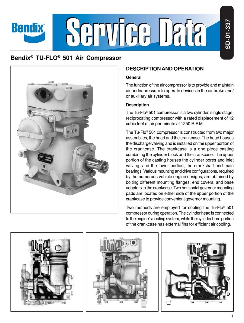
BENDIX TU-FLO 501 AIR COMPRESSOR User manual

BENDIX

BENDIX TU-FLO 501 AIR COMPRESSOR User manual

BENDIX BX-2150 User manual

BENDIX

BENDIX BX-2150 User manual

BENDIX BA-921 COMPRESSOR-STD-CLOSED ROOM User manual

BENDIX

BENDIX BA-921 COMPRESSOR-STD-CLOSED ROOM User manual

BENDIX BX2150 AIR COMP-BW1424- User manual

BENDIX

BENDIX BX2150 AIR COMP-BW1424- User manual

BENDIX TU-FLO 700 COMPRESSOR User manual

BENDIX

BENDIX TU-FLO 700 COMPRESSOR User manual

BENDIX TU-FLO 550 COMPRESSOR User manual

BENDIX

BENDIX TU-FLO 550 COMPRESSOR User manual

BENDIX TU-FLO 750 COMPRESSOR Mounting instructions

BENDIX

BENDIX TU-FLO 750 COMPRESSOR Mounting instructions

BENDIX SNA-01 Mounting instructions

BENDIX

BENDIX SNA-01 Mounting instructions

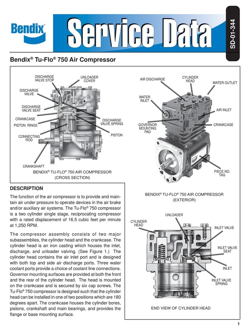
BENDIX TU-FLO 750 COMPRESSOR User manual

BENDIX

BENDIX TU-FLO 750 COMPRESSOR User manual

BENDIX TU-FLO 400-500-1000 AIR COMPRESSOR User manual

BENDIX

BENDIX TU-FLO 400-500-1000 AIR COMPRESSOR User manual

BENDIX BX-2150 User manual

BENDIX

BENDIX BX-2150 User manual

BENDIX 360CC User manual

BENDIX

BENDIX 360CC User manual

BENDIX BA-921 COMPRESSOR-STD-CLOSED ROOM Mounting instructions

BENDIX

BENDIX BA-921 COMPRESSOR-STD-CLOSED ROOM Mounting instructions

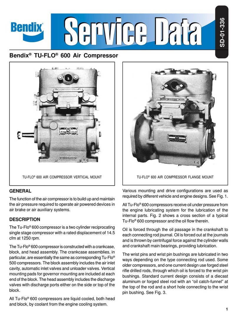
BENDIX TU-FLO 600 AIR COMPRESSOR User manual

BENDIX

BENDIX TU-FLO 600 AIR COMPRESSOR User manual

BENDIX DURAFLO 596 COMPRESSOR User manual

BENDIX

BENDIX DURAFLO 596 COMPRESSOR User manual

BENDIX BA-922 COMPRESSOR User manual

BENDIX

BENDIX BA-922 COMPRESSOR User manual

Popular Air Compressor manuals by other brands

Raider RD-AC06 user manual

Raider

Raider RD-AC06 user manual

Motomaster 299-6952-8 instruction manual

Motomaster

Motomaster 299-6952-8 instruction manual

Pattfield Ergo Tools PE-3050 user manual

Pattfield Ergo Tools

Pattfield Ergo Tools PE-3050 user manual

Gardner Denver AirSmart VS135A Operating and service manual

Gardner Denver

Gardner Denver AirSmart VS135A Operating and service manual

Utile LGA12 Installation, operation & maintenance instructions

Utile

Utile LGA12 Installation, operation & maintenance instructions

CruzPro PR60 Installation

CruzPro

CruzPro PR60 Installation

Vmac VR70 installation manual

Vmac

Vmac VR70 installation manual

Black & Decker Start-It 90550870 instruction manual

Black & Decker

Black & Decker Start-It 90550870 instruction manual

Husky 41004 Operator's manual

Husky

Husky 41004 Operator's manual

Brooks 8200 Installation & operation manual

Brooks

Brooks 8200 Installation & operation manual

Facom FCXCMD152WE manual

Facom

Facom FCXCMD152WE manual

Sullair TS20C user manual

Sullair

Sullair TS20C user manual

Alsafix ALAIR 20/255 User manual and  spare parts list

Alsafix

Alsafix ALAIR 20/255 User manual and spare parts list

L&W LW 225 E operating instructions

L&W

L&W LW 225 E operating instructions

Stealth SAQ-11018 Operator's manual

Stealth

Stealth SAQ-11018 Operator's manual

Vulcan-Hart 176-6799 instruction manual

Vulcan-Hart

Vulcan-Hart 176-6799 instruction manual

TECH DAC001 owner's manual

TECH

TECH DAC001 owner's manual

DeWalt DXCMTA5590412 instruction manual

DeWalt

DeWalt DXCMTA5590412 instruction manual

manuals.online logo
manuals.online logoBrands
  • About & Mission
  • Contact us
  • Privacy Policy
  • Terms and Conditions

Copyright 2025 Manuals.Online. All Rights Reserved.