BENDIX TU-FLO 400-500-1000 AIR COMPRESSOR User manual

1
TU-FLO®400 Air Compressor TU-FLO®500 Air Compressor
TU-FLO®1000 Air Compressor
®
Bendix®TU-FLO®400, 500, 1000 Air Compressors
SD-01-326

2
DESCRIPTION AND OPERATION
GENERAL
Thefunctionoftheaircompressoristobuildupandmaintain
theair pressurerequired tooperate airpowered devicesin
air brake or air auxiliary systems.
DESCRIPTION
Tu-Flo®Type 400, 500, and 1000 compressors are single
stage,reciprocating pistontypecompressors. Tu-Flo®400
(Fig. 1) and 500 (Fig. 2) compressors have two cylinders
while the Tu-Flo®1000 compressor (Fig. 3) is a V-type
designhavingfourcylinders. TheratedcapacityofallBendix
compressors is their piston displacement in cubic feet per
minute when operating at 1,250 RPM. The rated capacity
oftheTu-Flo®400compressoris7-1/4cubicfeetperminute.
The Tu-Flo®500 compressor is rated at 12 cubic feet per
minuteand the Tu-Flo®1000compressor hasa rating of24
cubic feet per minute.
Tu-Flo®typecompressorshave automatic typeinletvalves.
Theirunloadingmechanismsarelocatedinthecylinderblock
andtheyhave noexternalmoving parts. Both airandwater
cooled type compressors are available. Various mounting
anddriveadaptationsareusedasrequiredbydifferentvehicle
engine designs (Fig. 4).
Compressors are either engine or self-lubricated. The
majorityusedare theenginelubricatedtypes (Fig. 5)which
obtainthe oil necessaryto lubricatetheirmoving partsfrom
the engines on which they are mounted. To meet the
requirements of some manufacturers and for field
installations,self-lubricatedtypes(Fig. 6)areavailable. They
are compressors having a self-contained oil supply and
pumping system.
Themethodoflubricatingthemovingpartsofthecompressor
is the same in either type. Oil is forced through the oil
passagein thecrankshaft and outaround eachconnecting
rodjournal. Theturning motionofthecrankshaft throwsthe
oil that is forced out at the journals, against the cylinder
bores and crankcase walls, lubricating the bores and
crankshaftbearings.
The wrist pins and wrist pin bushings are lubricated in two
waysdependinguponthetypeconnecting rods used. Older
designcompressorshadforgedsteelrifle-drilledrodsthrough
whichoilwasforcedtothewristpinbushings. Laterversions
FIGURE 2 - TU-FLO®500AIR COMPRESSOR
FIGURE 3 - TU-FLO®1000AIR COMPRESSOR
FIGURE 1 - TU-FLO®400AIR COMPRESSOR
FIGURE4 - VARIOUS COMPRESSORMOUNTINGS

3
had either die cast aluminum, cast ductile iron, or forged
steelrods which werenot rifledrilled but were drilled atthe
top of the rod. The wrist pins and bushings are lubricated
by oil dripping from a drip-boss on the piston into a
“catch-funnel” at the top of the rod and through the drilled
passage to the bushings and pins. (SEE FIG. 7)
Anameplateis attachedtothecrankcaseofallcompressors.
Itshows the piecenumber,typeand serialnumber(Fig. 8).
A nameplate with a black background denotes a new
compressor, whereas a nameplate with a red background
designates that the compressor is a factory reconditioned
unit. All compressors are identified by the piece number
which is the number to use when reference is made to a
particular compressor. The type and serial number is
supplementaryinformation.
OPERATION
GENERAL
Allcompressorsruncontinuouslywhiletheengineisrunning,
but actual compression of air is controlled by a governor,
which stops or starts the compression of air by loading or
unloadingthe compressorin conjunctionwith its unloading
mechanism. Thisisdonewhentheairpressureinthesystem
reachesthe desiredmaximum orminimum pressures.
INTAKEAND COMPRESSION (Loaded)
Duringthedownstrokeofthepiston,aslightvacuumcreated
abovethe pistoncauses theinlet valveto move offits seat.
Atmosphericair isdrawnin throughthecompressor intake,
bythe open inletvalve, andontop ofthepiston (Fig. 9). As
thepiston startsitsupward stroke,the air thatwas drawnin
onthedownstroke isbeingcompressed. Now,airpressure
on top of the inlet valve plus the force of its spring, returns
theinlet valve to its seat. Thepiston continuesthe upward
strokeand compressesthe airsufficiently toovercome the
dischargevalvespringandunseatthe dischargevalve. The
compressedairthenflows by theopendischargevalve, into
the discharge line and on to the reservoirs (Fig. 10).
FIGURE 5
ENGINELUBRICATEDTYPE FIGURE 6
SELF-LUBRICATEDTYPE
FIGURE 9
FIGURE 10
DISCHARGE
VALVE
PISTON
STROKE
TO GOVERNOR
INTAKE
STRAINER
UNLOADER PLUNGER
INLETVALVE
TO RESERVOIR
INTAKE
DISCHARGE
VALVE
PISTON
STROKE
TO GOVERNOR
INTAKE
STRAINER
UNLOADER PLUNGER
INLETVALVE
TO RESERVOIR
COMPRESSION
FIGURE8- COMPRESSOR NAMEPLATE
FIGURE 7- PISTONS & CONNECTING RODS
NEWDESIGN
WRIST PIN
BUSHING
“CATCH FUNNEL”
DIECAST
PISTON
DIE CAST
CONNECTING ROD
OLD DESIGN
OIL
PASSAGE
WRIST PIN
WRIST PIN
BUSHING
PISTON WRIST PIN
LOCK WIRE
CAST IRON
PISTON
STEEL
CONNECTING
ROD

4
Asthe pistonreaches the top of itsstroke andstarts down,
thedischargevalve springreturnsthe dischargevalveto its
seat. This prevents the compressed air in the discharge
line from returning to the cylinder bore as the intake and
compression cycle is repeated.
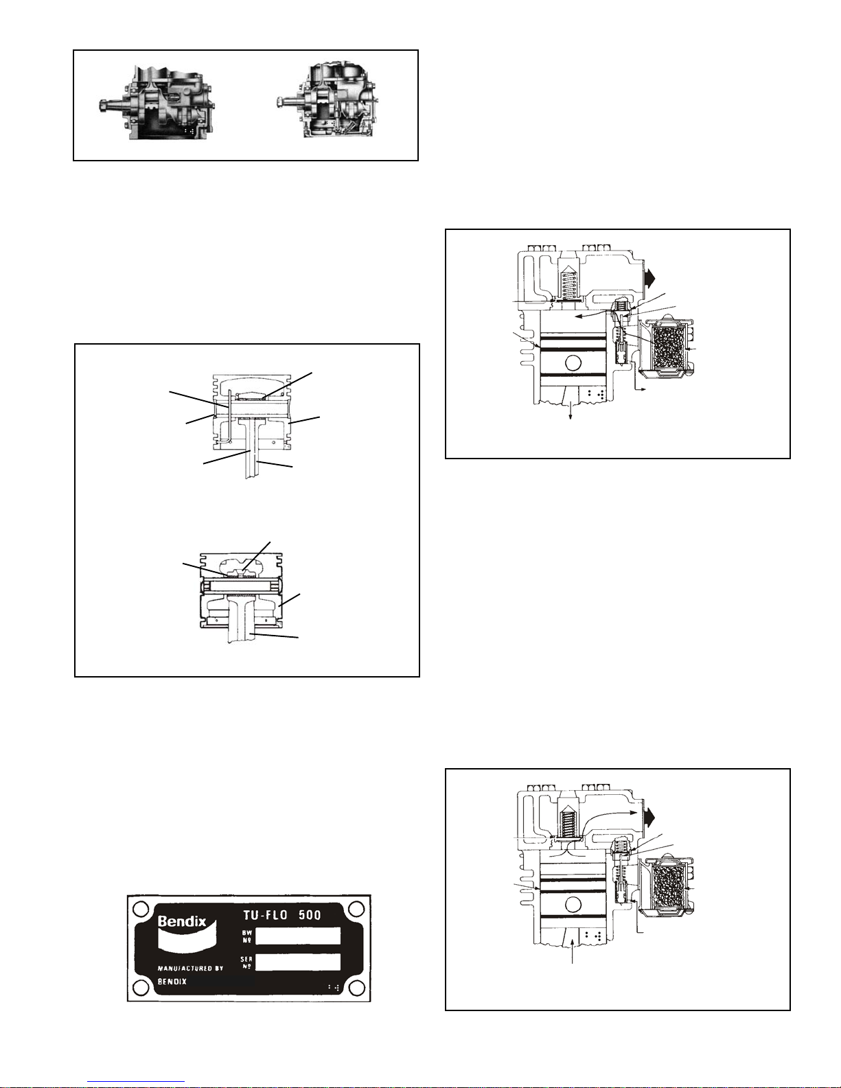
NON-COMPRESSION(Unloaded)
When the air pressure in the reservoir reaches the high
pressuresettingofthegovernor,thegovernoropens,allowing
airto passfrom the reservoirthrough thegovernor andinto
the cavity beneath the unloader pistons. This lifts the
unloaderpistons andplungers. Theplungers moveupand
hold the inlet valves off their seats (Fig. 11).
With the inlet valves held off their seats by the unloader
pistons and plungers, air is merely pumped back and forth
between the two cylinders. When air is used from the
reservoirandthe pressure dropstothe low pressuresetting
of the governor, the governor closes, and in doing so,
exhausts the air from beneath the unloader pistons. The
unloader saddle spring forces the saddle, pistons and
plungers down and the inlet valves return to their seats.
Compressionis thenresumed.
COMPRESSOR & THE AIR BRAKE SYSTEM
GENERAL
The compressor is part of the total air brake system, more
specifically,the chargingportionof theairbrake system.As
acomponent inthe overallsystem its condition,duty cycle,
proper installation and operation will directly affect other
components in the system.
Powered by the vehicle engine, the air compressor builds
theairpressurefortheairbrakesystem.Theair compressor
istypically cooledby theengine coolantsystem, lubricated
by the engine oil supply and has its inlet connected to the
engine induction system.
As the atmospheric air is compressed, all the water vapor
originally in the air is carried along into the air system, as
well as a small amount of the lubricating oil as vapor. If an
air dryer is not used to remove these contaminants prior to
enteringtheairsystem,themajority,butnotall,willcondense
in the reservoirs. The quantity of contaminants that reach
the air system depends on several factors including
installation,maintenanceandcontaminanthandlingdevices
inthesystem.Thesecontaminantsmusteitherbeeliminated
prior to entering the air system or after they enter.
DUTYCYCLE
The duty cycle is the ratio of time the compressor spends
buildingairtothe totalengine running time.Aircompressors
are designed to build air (run "loaded") up to 25% of the
time. Higher duty cycles cause conditions that affect air
brake charging system performance which may require
additional maintenance. Factors that add to the duty cycle
are: air suspension, additional air accessories, use of an
undersizedcompressor,frequentstops, excessiveleakage
from fittings, connections, lines, chambers or valves, etc.
RefertoTableAintheTroubleshootingsectionfor a guideto
variousdutycyclesandtheconsiderationthatmustbe given
tomaintenance ofother components.
COMPRESSORINSTALLATION
While the original compressor installation is usually
completed by the vehicle manufacturer, conditions of
operation and maintenance may require additional
consideration.The following presentsbase guidelines.
DISCHARGELINE
Thedischarge line allowsthe air,water-vapor andoil-vapor
mixture to cool between the compressor and air dryer or
reservoir.The typical sizeof a vehicle'sdischarge line, (see
column2ofTableAintheTroubleshootingsection)assumes
a compressor with a normal (less than 25%) duty cycle,
operating in a temperate climate. See Bendix and/or other
airdryer manufacturer guidelinesas needed.
The discharge line must maintain a constant slope down
fromthe compressorto theair dryerinlet fittingor reservoir
toavoidlowpointswhereicemay formandblocktheflow. If,
instead, ice blockages occur at the air dryer or reservoir
inlet,insulation may beadded here,or if theinlet fittingis a
typical 90 degree fitting, it may be changed to a straight or
45degreefitting.Shorterdischargeline lengths orinsulation
may be required in cold climates.
While not all compressors and charging systems are
equippedwith adischargeline safetyvalvethis component
isrecommended.Thedischargelinesafetyvalve is installed
in the cylinder head or close to the compressor discharge
portand protects againstover pressurizing thecompressor
inthe eventof adischarge line freezeup.
DISCHARGELINE TEMPERATURE
When the temperature of the compressed air that enters
the air dryer is within the normal range, the air dryer can
removemost ofthe chargingsystem oil. If the temperature
ofthe compressed air is abovethe normalrange, oil as oil-
vapor is able to pass through the air dryer and into the air
system. Larger diameter discharge lines and/or longer
dischargeline lengthscan helpreduce thetemperature.
FIGURE 11
DISCHARGE
VALVE
PISTON
STROKE
TO GOVERNOR
INTAKE
STRAINER
UNLOADER
PLUNGER
INLETVALVE
TO RESERVOIR
UNLOADING

5
PREVENTIVEMAINTENANCE
Regularly scheduled maintenance is the single most
importantfactorinmaintainingtheairbrakechargingsystem.
RefertoTableAintheTroubleshootingsectionfor a guideto
variousconsiderationsthatmustbegiventothemaintenance
of the compressor and other related charging system
components.
Ifthecompressoris aself-lubricatedtype,itsoil levelshould
bechecked daily. Theoil levelshould bekept betweenthe
bottomofthe dipstickthreadsand the bottomofthe dipstick
(Fig. 13). Every8,000 milesor300 operatinghours, the oil
shouldbe drainedandrefilled withSAE 10-20-30.
FIGURE 12A - SYSTEM DRAWING
AirDryer
Reservoir Drain
Service Reservoir
(Supply Reservoir)
Compressor
Governor
(Governor plus Synchro valve
for the Bendix®DuraFlo™596
Compressor)
Discharge
Line Optional“Ping” Tank
OptionalBendix®PuraGuard®QC™
OilCoalescing Filter
The Air Brake Charging System supplies the
compressedair for thebraking systemaswell asotherair
accessories for the vehicle. The system usually consists
of an air compressor, governor, discharge line, air dryer,
andservicereservoir.
FIGURE 12B - DISCHARGE LINE SAFETY VALVE
HOLE
THREAD
Theair dryer containsa filter thatcollects oil droplets,and a
desiccantbedthatremovesalmostalloftheremainingwater
vapor. The compressed air is then passed to the air brake
service (supply) reservoir. The oil droplets and the water
collected are automatically purged when the governor
reaches its "cut-out" setting.
For vehicles with accessories that are sensitive to small
amounts of oil, we recommend installation of a Bendix®
PuraGuard®QC™oilcoalescing filter,designed tominimize
the amount of oil present.
COOLING
Tu-Flo®400,500or1000 compressors maybeair-cooledor
water- cooled and in some instances will have air-cooled
blocks and water-cooled heads. The air-cooled versions
areeasilyrecognizedbytheexternal fins. The water-cooled
versionsare cooledbyvehicle coolant.
FIGURE 13 - OIL LEVEL - SELF-LUBRICATED
COMPRESSOR
POLYURETHANE SPONGE STRAINER (Fig. 14)
Remove and wash all of the parts. The strainer element
shouldbe cleanedor replaced. Ifthe elementis cleaned, it
should be washed in a commercial solvent or a detergent
and water solution. The element should be saturated in
clean engine oil, then squeezed dry before replacing it in
thestrainer. Besure to replacethe airstrainer gasketif the
entireair straineris removedfrom thecompressor intake.

6
FIGURE 14 - POLYURETHANE SPONGE STRAINER
FIGURE 15 - DRY ELEMENT- PLEATED PAPERAIR
STRAINER
FIGURE16- COMPRESSOR INTAKEADAPTER
DRY ELEMENT - PLEATED PAPER AIR
STRAINER (FIG. 15)
Removethe springclips from eitherside ofmounting baffle
andremove the cover. Replace thepleatedpaper filter and
remount the cleaned cover making sure the filter is in
position. Be sure to replace the air strainer gasket if the
entire air strainer is removed from the compressor intake.
(NOTE:Somecompressorsarefittedwithcompressorintake
adapters(Fig. 16) whichallowthe compressorintake tobe
connected to the engine air cleaner.) In this case, the
compressor receives a supply of clean air from the engine
air cleaner. When the engine air filter is changed, the
compressorintakeadaptershould bechecked. Ifitisloose,
remove the intake adapter, clean the strainer plate, if
applicable, and replace the intake adapter gasket, and
reinstalltheadapter securely. Check lineconnections both
at the compressor intake adapter and at the engine air
cleaner. Inspecttheconnectingline for rupturesand replace
it if necessary.
AIR LEAKAGE TESTS
Leakage past the discharge valves can be detected by
removingthedischargeline, applyingshopairback through
the discharge port and listening for escaping air. Also the
dischargevalves andthe unloader pistonscan bechecked
forleakage bybuilding up the air systemuntil thegovernor
cutsout,thenstoppingtheengine. Withtheenginestopped,
carefully listen for escaping air at the intake. To pinpoint
leakage if noted, squirt oil around the unloader pistons. If
there is no noticeable leakage at the unloader pistons, the
dischargevalves may beleaking.
Ifthe compressordoes notfunctionas describedabove, or
leakageis excessive,it isrecommendedthat itbe returned
to the nearest Bendix authorized distributor for a factory
rebuiltcompressorunderthe repairexchangeplan. Ifthis is
notpossible, thecompressor canbe repairedwith genuine
Bendixparts,inwhich casethefollowinginformation should
provehelpful.
REMOVING AND INSTALLING
REMOVING
Theseinstructionsaregeneralandinsomecases additional
precautions must be taken.
Drain air brake system.
If water-cooled type compressor, drain engine cooling
system, compressor cylinder head and block.
Disconnect all air lines, water and oil lines to and from
compressor.
Removecompressor mountingbolts andcompressor from
engine.
Use a gear-puller to remove the gear or pulley from
compressorcrankshaft.
INSTALLATION
ENGINE-LUBRICATEDTYPES
Clean oil supply line. Before connecting this line to the
compressor, run the engine briefly to be sure oil is flowing
freelythrough thesupply line.
Clean the oil return line or return passages through the
brackets; these passages must be unrestricted so oil can
returnto theengine.

7
Prelubricate compressor cylinder walls and bearings with
cleanengine oilbeforeassembling compressor.
Always use a new mounting gasket and be sure oil hole in
gasket and compressor is properly aligned with oil supply
line.
SELF-LUBRICATEDTYPES
Fill compressor crankcase with clean engine oil before
operatingcompressor. Refer to “Tabulated Data”sectionfor
properamount.
ALLTYPES
Inspect pulley or gear and associated parts for wear or
damage. Theymustbeaneatfit oncompressorcrankshaft.
Replacepulley orgearif wornor damaged.
Installpulleyorgear on compressorcrankshaftmakingsure
it properly contacts the shaft and does not ride the key.
Tighten crankshaft nut to 65-70 ft. lbs. and install cotter
pin.
Besurethe aircleaneris clean andproperlyinstalled. If the
compressor intake is connected to either the engine air
cleaner or supercharger, these connections must be tight
withno leakage.
Clean or replace any damaged or dirty air or water lines
which may be corroded, before connecting them to the
compressor. Use a new discharge fitting gasket.
Aligncompressor driveand adjustproper belt tension.
Tightenmountingbolts securelyand evenly.
After installation, run compressor and check for air, oil, or
water leaks at compressor connections. Also check for
noisyoperation.
Checkthe exterior ofthe compressor forthe presence ofoil
seepageandrefer totheTROUBLESHOOTING section for
appropriatetests andcorrective action.
OIL PASSING
All reciprocating compressors currently manufactured will
pass a minimal amount of oil. Air dryers will remove the
majority of oil prior to entrance into the air brake system.
ForparticularlyoilsensitivesystemstheBendix®PuraGuard®
QC™oil coalescing filter can be used in conjunction with a
Bendixair dryer.
If compressor oil passing is suspected, refer to the
TROUBLESHOOTING section and TABLE A for the
symptoms and corrective action to be taken. In addition,
Bendix has developed the "Bendix Air System Inspection
Cup"orBASICtesttohelpsubstantiatesuspectedexcessive
oilpassing.The stepstobefollowed whenusingthe BASIC
test are presented in APPENDIX A at the end of the
TROUBLESHOOTINGsection.
REMOVING AND DISASSEMBLY
REMOVING
These instructions are general and are intended to be a
guide. In some cases additional preparations and
precautionsarenecessary. Chockthewheelsof the vehicle
anddraintheairpressurefromallthereservoirsinthesystem.
Drain the engine cooling system and the cylinder head of
thecompressor. Disconnectallair,waterandoillinesleading
to and from the compressor. Remove the drive gear(s) or
pulley from the compressor crankshaft using a gear puller.
Inspect the pulley or gear and associated parts for visible
wear or damage. Since these parts are precision fitted,
they must be replaced if they are worn or damaged.
DISASSEMBLY
GENERAL
Remove road dirt and grease from the exterior of the
compressorwithacleaningsolvent. Before the compressor
is disassembled, the following items should be marked to
showtheirrelationship whenthecompressor is assembled.
Mark both the front and rear end cover in relation to the
crankcase. Markthe driveend ofthe crankshaftin relation
tothe front endcover and thecrankcase. Mark thecylinder
head in relation to the block and block to crankcase. Mark
thebase plateor baseadapter in relationto thecrankcase.
Aconvenient methodto indicatethe aboverelationships is
to use a metal scribe to mark the parts with numbers or
lines. Donotuse a markingmethodthat can bewipedoff or
obliterated during rebuilding, such as chalk. Remove all
compressor attachments such as governors, air strainers
or inlet fittings, discharge fittings and pipe plugs.
CYLINDERHEAD
Remove the cylinder head cap screws and tap the head
with a soft mallet to break the gasket seal. Remove the
inletvalve springsform thehead and inletvalves fromtheir
guidesinthe block. Removeinletvalveguides fromaround
theinletvalve seats ontheblock, taking carenottodamage
seats. Scrape off any gasket material from the cylinder
head and block. Unscrew the discharge cap nuts from the
headandremovethedischargevalvesandsprings. Inspect
the discharge valve seats for nicks, cracks, and excessive
wearand remove andreplace ifnecessary.
Thedischarge valvecapnuts shouldbe inspectedfor wear
and replaced if excessive peening has occurred. To
determineif excessivepeening has occurred,measure the
dischargevalvetravel. Dischargevalvetravelmustnotexceed
.056in. forthe Tu-Flo®400compressor and.046 in.for the
Tu-Flo®500and 1000compressors.
CRANKCASE BASE PLATE OR ADAPTER
Remove the cap screws securing the base plate or base
adapter. Tapwithsoftmallettobreakthegasketseal. Scrape
offany gasketmaterialfromcrankcaseandplate or adapter.
CONNECTING ROD ASSEMBLIES
(NOTE: Before removing the connecting rods, mark each
connecting rod and its cap. Each connecting rod
ismatchedto itsowncap for properbearingfit, and
these parts must not be interchanged.)

8
Straighten the prongs of the connecting rod bolt lock strap
and remove the bolts and bearing caps. Push the piston
withtheconnectingrodsattachedoutthetopofthecylinders
of the crankcase. Replace the bearing caps on their
respectiveconnecting rods. Removethe pistonrings from
the pistons. If the pistons are to be removed from the
connecting rods, remove the wrist pin lock wires or teflon
plugs and press the wrist pins from the pistons and
connectingrods.
Ifthe pistonsare removedfrom therod, inspectthe bronze
wristpin bushing. Press outand replace the bushing ifit is
excessively worn. (See Inspection of Parts.) Discard the
pistonringsandtheconnectingrodjournalbearings. Discard
the wrist pin bushings if they were removed. New Tu-Flo®
400 compressors manufactured after approximately
September1977 willhave connecting rodswithout bearing
inserts. Repair size rods will have inserts.
REMOVING AND DISASSEMBLING BASE PLATE
SELF-LUBRICATED TYPE COMPRESSORS(Fig. 18)
Removescrews thathold baseplate. Remove baseplate.
Removeoilrelief valvesetscrew,thenoil reliefvalve.
Removeoil strainerretainingring andliftout oilstrainer.
Unless it is necessary, the oil pump piston bushing should
notberemoved. Ifnecessary,removethebushingsetscrew,
thenbushing andshim.
Remove cotter pin from oil rod cap nuts, remove nuts, oil
pump piston rod and cap.
CRANKCASE(Fig. 19)
Removeend coverwith oilseal, removeend covergasket.
Replaceoil sealaftercleaningend cover.
Remove cap screws that hold opposite end cover to
crankcase; remove end cover and its gasket. Some
compressors have crankcases that have a shoulder for
positioning the crankshaft. In these cases the crankshaft
mustbe removed throughone particularend.
FIGURE 17 - TU-FLO® 400AIR COMPRESSOR VERTICALMOUNT - ENGINE LUBRICATED
FIGURE 18 - BASE PLATE SELF-LUBRICATED TYPE
COMPRESSOR

9
CLEANING AND INSPECTION OF PARTS
CLEANING
All parts should be cleaned thoroughly in a good cleaning
solventbeforeinspection.
CYLINDERHEADASSEMBLY
Removeall carbondepositsfrom dischargecavitiesand all
rust and scale from cooling cavities of cylinder head body.
Scrape all foreign matter from body surfaces and use air
pressure to blow dirt particles from all cavities.
Dischargevalvescanbedressedbylappingthemon a piece
of fine crocus cloth on a flat surface, provided they are not
excessivelyworn.
CYLINDERBLOCK
Clean carbon and dirt from inlet and unloader passages.
Use air pressure to blow carbon and dirt deposits from
unloaderpassages.
Inlet valves, as in the case of discharge valves, not worn
excessively, can be cleaned by lapping them on a piece of
fine crocus cloth on a flat surface.
OILPASSAGE
Clean thoroughly all oil passages through crankshaft,
connectingrods, crankcase,end coversand base plate. If
necessary, inspect passages with a wire and blow foreign
matter out with air pressure.
CRANKCASE - SELF-LUBRICATED TYPE
Thebreathershould bethoroughlywashed andcleaned.
The oil pump check valve in the base should be removed
andreplaced. Itis importantwhentheoil pumpcheckvalve
isreplaced thatitbe installedcorrectly with theball stoppin
end pressed in first. When installed, the ball and its seat
shouldbe visiblefrom thecrankcase base.
INSPECTION OF PARTS
CYLINDERHEADBODY
Inspectcylinder head bodyfor cracksor damage.
WATER-COOLEDTYPE
Use air pressure to test water jackets of cylinder head and
block for leakage. Replace unit if leakage is found.
DISCHARGEVALVESAND SEATS
Ifdischargevalvesare wornandgroovedwheretheycontact
the seats, they should be replaced. If the discharge valve
seatsarewornexcessivelysothatthereisnolongerenough
metal left to reclaim them by lapping, the seats should be
replaced.
DISCHARGE VALVE SPRINGAND CAP NUTS
Replaceall useddischarge valvesprings andcap nuts.
FIGURE 20 - CYLINDER BLOCK - EXPLODED VIEW
Pressthe crankshaftandball bearingsfromthe crankcase,
thenpressballbearingsfromcrankshaft. Manycompressors
willhavesleeve-typebearingsinthe crankcase orintheend
cover. If the clearance between crankshaft journal and
bearing exceeds .0065 in. the sleeve bearing should be
replacedwithappropriate undersize.
BLOCK (Fig. 20)
If compressor is fitted with an air strainer, inlet elbow or
governor,removesame.
Remove cap screws securing cylinder block to crankcase;
separatecrankcaseandcylinderblockandscrapeoffgasket.
Removeunloaderspring,springsaddleandspringseatfrom
cylinder block.
Removeunloader guidesandplungers and,withthe useof
shopair,blowunloaderpistonsoutofcylinderblockunloader
pistonbores.
Removeinletvalveguides;inletvalveseatscanberemoved
butonlyiftheyarewornordamagedandarebeingreplaced.
Unloaderborebushingsshouldbeinspectedbutnotremoved
unlessthey aredamaged.
FIGURE 19 - CRANKCASE - TU-FLO®400 & 500AIR
COMPRESSORS
FIGURE 19A - CRANKCASE - TU-FLO®1000AIR
COMPRESSOR

10
CRANKCASEAND ENDCOVERS
Checkforcracksorbrokenlugsincrankcaseandendcovers.
Also check their oil passages to make sure they are open
andclean.
Ifan oilseal ringis usedin theend cover,check fitof ringin
ringgroove. Thereshouldbe0.008in.to0.015in.clearance
atthe gapwhen placed inthe endbore ofthecrankshaft. If
theoilring iswornthinor isdamaged,itshould bereplaced.
Inspect oil ring groove in end cover; if groove is worn
excessively replace end cover or machine groove for next
oversizeoil sealring.
Ifthecrankshaftmainbearingsareinstalledintheendcover,
check for excessive wear and flat spots and replace if
necessary.
CYLINDERBLOCK
Check for cracks or broken lugs on cylinder block. Also
checkunloaderbore bushingstobe suretheyare not worn,
rusted or damaged. If these bushings are to be replaced
they can be removed by running a 1/8 in. pipe thread tap
insidethebushing,then insertinga1/8in. pipe threadedrod
and pulling the bushing straight up and out. Do not use an
easy-outfor removing thesebushings.
INLET VALVESAND SEATS
If inlet valves are grooved or worn where they contact the
seat, they should be replaced. If the inlet valve seats are
worn or damaged so they cannot be reclaimed by facing,
theyshould bereplaced.
CYLINDERBORES
Cylinder bores which are scored or out of round by more
than 0.002 in. or tapered more than 0.003 in. should be
reboredorhonedoversize. Oversizepistonsareavailablein
0.010,0.020, and0.030 oversizes.
Cylinderbores must besmooth, straight andround.
Clearance between cast iron pistons and cylinder bores
should be between 0.002 in. minimum and 0.004 in.
maximum (Fig. 21).
PISTONS
Checkpistons forscores, cracksor enlargedring grooves;
replacepistonsifanyoftheseconditionsarefound. Measure
each piston with a micrometer in relation to the cylinder
borediameterto besurethe clearanceisbetween 0.002in.
minimum and 0.004 in. maximum.
Checkfitofwristpinsonpistonsandconnectingrodbushings.
Wrist pin should be a light press fit in pistons. If wrist pin is
loosefit, thepin,piston, orbothshould bereplaced. Check
fitofwristpininconnectingrodbushingbyrockingthepiston.
Thisclearance shouldnot exceed0.0015 in.Replace wrist
pin bushings if excessive clearance is found. Wrist pin
bushings should be reamed after being pressed into
connecting rods. Replace used wrist pin lock wires.
Tu-Flo®400 compressors manufactured after September
1977 will have Teflon plugs in each end of the wrist pins
insteadof thelockwire. TheTeflonplugs (pc. no. 292392)
may be used instead of the lock wires on all compressors.
See Fig. 22.
PISTON RINGS
Check fit of piston rings in piston ring grooves. Check ring
gap with rings installed in cylinder bores. Refer to Fig. 24
forcorrectgap andgrooveclearance.
All rings must be located in their proper ring grooves as
shown. Therings canbeidentified bythe widthandshould
beinstalled with thebevelor thepipmark(if any)towardthe
top of the piston. This applies to cast iron pistons (only as
shownabove).
Diecast pistonsuse five (5) narrow rings.
FIGURE 21 - MEASURING CYLINDER BORES
FIGURE 22 - TU-FLO®400AIR COMPRESSOR NEW STYLE
COMPRESSION
RINGS (2)
COMPRESSION
RINGS (2)

11
CRANKSHAFT
Check crankshaft screw threads, keyways, tapered ends
and all machined and ground surfaces for wear, scores, or
damage. Crankshaftjournals which areout of roundmore
than0.001in.mustbereground. Bearinginsertsareavailable
in0.010in., 0.020in.,and0.030 in.undersizesforreground
crankshafts. Mainbearing journalsmust bemaintained so
bearingsare snugfit. Theoil sealring groove orgrooves in
crankshaftsfitted with oil seal ringsmust notbe worn. The
ringgroove walls musthave agoodfinish andthey must be
square. Check to be sure the oil passages are open and
cleanthrough thecrankshaft.
CONNECTINGROD BEARINGS
Check connecting rod bearings on crankshaft journals for
proper fit. Used bearing inserts should be replaced.
Connectingrod capsare notinterchangeable. The locking
slots of the connecting rod and cap should be positioned
adjacentto eachother.
Clearance between the connecting rod journal and the
connecting rod bearing must not be less than 0.0003 in. or
morethan 0.0021in.after rebuilding.
MAINBEARINGS
Check for wear or flat spots; if found, bearings should be
replaced. Iftypewithsleeve bearing,thisbearingshould be
checkedfor scoresand wearand replacedif necessary.
UNLOADERMECHANISM
Usedunloadermechanism shouldbereplaced byunloader
kits265014forTypeTu-Flo®400 compressors and265015
forTypesTu-Flo®500and 1000compressors. TheTu-Flo®
1000compressor requirestwo kitsper compressor.
Thenewunloader pistonsshouldbe alooseslidingfit inthe
unloaderpiston bores ofthe cylinderblock.
PARTS SPECIAL TO SELF-LUBRICATED
TYPE COMPRESSORS
OILPUMP SCREEN
Check oil pump screen to be sure it is clean and not
damaged;replaceif damaged.
OIL PUMP PISTON AND BUSHING
Check fit of oil pump piston in base plate pump bushing. It
must be a medium sliding fit. If excessive clearance is
found,the oilrod and/orbushing mustbe replaced.
OIL PUMPRELIEF VALVE
Iftheoilpump reliefvalveisdefective,it shouldbereplaced.
OIL PUMPCHECK VALVE
Thecheck valve should be replaced. Itcan bechecked by
applying air pressure back through the pin stop end and
noting that the ball check seals on its seat.
REPAIRS
DISCHARGEVALVESAND SEATS
If discharge valve seats merely show signs of slight wear,
they can be dressed by using a lapping stone, grinding
compound and grinding tool. Install new discharge valves
andvalvesprings.
To testforleakagebythe dischargevalves,applyabout100
poundsof air pressurethrough the cylinderhead discharge
portandapplysoap sudsatthedischargevalves and seats.
Leakage which will permit the formation of bubbles is
permissible.
Ifexcessiveleakageisfound,leavethe air pressureapplied,
andwith the useof afibreor hardwooddowel and hammer,
tapthe dischargevalves offtheir seatsseveral times. This
willhelp thevalves toseat and shouldreduce anyleakage.
With the air pressure still applied at the discharge port of
thecylinder head,check forleakageat thedischarge valve
cap nuts. No leakage is permissible.
INLET VALVESAND SEATS
If inlet valve seats show sign of slight nicks or scratches,
theycan be redressedwith afinepiece ofemerycloth orby
lappingwithalappingstone,grindingcompoundandgrinding
tool. If the seats are excessively damaged to the extent
that they cannot be reclaimed, they should be replaced.
Thedimension fromthe top ofthe cylinderblock tothe inlet
valve seat should not exceed 0.118 in. nor be less than
0.101in.
FIGURE 23 - TU-FLO®400AIR COMPRESSOR OLD STYLE
TU-FLO®400 AIR COMPRESSOR
CORRECT GROOVE
CLEARANCE
.0015”
.0030”
CORRECT GAP
CLEARANCE WITH RING
IN CYLINDER
.0035”
.014”
FIGURE 24 - PISTON RING POSITIONS - GAPS AND
GROOVE CLEARANCE
TU-FLO®500 & 1000 AIR COMPRESSOR
CORRECT GROOVE
CLEARANCE
.0035”
.0035”
CORRECT GAP
CLEARANCE WITH RING
IN CYLINDER
.0035”
.014”
.002”
.004”
WIDE
NARROW
WIDE
NARROW

12
Slightlyworn orscratched inletvalves canbe reclaimedby
lappingthemonapieceof fine crocusclothonaflatsurface,
but it is suggested that new inlet valves be installed.
ASSEMBLY
INSTALLING CYLINDER BLOCK
Position cylinder block gasket and block on crankcase
according to markings made prior to disassembly. Using
cap screws with lock washers, secure cylinder block to
crankcase.
INSTALLING CRANKSHAFT
If the crankshaft is fitted with oil seal rings, install rings.
Positionball bearings andcrankshaft incrankcase,making
surethedrive endofthecrankshaft ispositionedasmarked
beforedisassembly.
If one end of the crankcase is counterbored for holding a
bearing,besurethecrankshaftisinstalledthroughthecorrect
end of the crankcase.
Carefullypresscrankshaftandbearingsintocrankcaseusing
arborpress.
Positiona newrear endcover gasket,when used,over the
rear end of the crankcase, making sure the oil hole in the
gasket lines up with the oil hole in the crankcase. Position
endcoverwithoil sealring,ifused, installed overcrankcase
andend cover gasket. Theend covershouldbe positioned
correctly in relation to the oil holes in the gasket and
crankcase. Secureendcoverto crankcase withcapscrews
and lock washers.
If the opposite end cover requires an oil seal which was
removed on disassembly, a new seal should be pressed
intoendcover. Positionnewendcover gasketandcarefully
installendcoverovercrankshaft andtocrankcase,avoiding
damageto the seal. Secure end coverwith capscrew and
lock washers.
PISTONSANDCONNECTING RODS
If new wrist pin bushings are to be used, they should be
pressed into the connecting rods so that the oil hole in the
bushinglines upwiththe onein therod. The new bushings
shouldthenbereamed or honedtoprovidebetween0.0002
in and 0.0007 in. clearance on the wrist pin. Position
connecting rod in piston and press in wrist pin so that
lockwirehole inthe pinaligns withthat ofthe piston. Install
newlockwire through pistonand wrist pinand lock sameby
snapping short end into lockwire hole at the bottom of the
piston (Fig. 7). Teflon plugs in wrist pin ends may be used
instead of the lockwires (Fig. 22).
Installpiston ringsin correctlocation with ring pipmarks up
(Fig. 24). Stagger the position of the ring gaps.
Prelubricate piston, piston rings, wrist pin and connecting
rod bearings with clean engine oil before installing them in
thecompressor.
Remove connecting bolts and bearing cap from one
connecting rod. Turn crankshaft so one of its connecting
rodjournals is inthedownward, centerposition. Compress
the rings with a ring compression tool and insert the
connecting rod with piston through the top of the cylinder
whosejournalis down. Positionandattach thebearingcap
to the connecting rod, making sure the bolt lock washers
areproperly positionedonthe cap. Tightenconnecting rod
bolts evenly and bend the two new lock washer prongs up
againstthehexhead of thebolt. Installtheotherconnecting
rod and piston in the same manner.
FIGURE 25 - UNLOADER MECHANISM
UNLOADERMECHANISM (Fig. 25)
The unloader pistons and their bores must be lubricated
with special lubricant piece number 239379 (dimethyl
polysiloxane) prior to installation. If new unloader kits are
beinginstalled, thepistons inthe kitare alreadylubricated.
Installtheunloaderpistonsintheir bores with cautionagainst
cuttingthegrommetsordistortingtheback-uprings. Position
unloaderplungers intheir guidesand slipthem inand over
the tops of the pistons.
Installtheunloader springseatin thecylinderblock;a small
hole is drilled in the block for this purpose. Position the
saddle between unloader piston guides so its forks are
centeredon the guides. Installtheunloader spring,making
sure it seats over the spring seats both in the block and on
thesaddle.
Installinletvalveseatsiftheyhavebeenpreviouslyremoved.
Positionandinstall inletvalveguides, thendropinlet valves
intheir guides. Thereshould bea loosesliding fitbetween
guidesandvalves.
CYLINDERHEADASSEMBLY
Ifpreviously removed,the discharge valveseats shouldbe
installed. Drop discharge valves into their seats. Install
dischargevalve springsandcap nuts.
Place the inlet valve springs in the cylinder head. Use a
small quantity of grease to hold them in place, just enough
grease to keep the springs from falling out. Place cylinder
headgasketoncylinder block. Carefully aligncylinderhead
assemblyonblockandinstallcapscrews with lockwashers.
Tighten securely and evenly cap screws that hold cylinder
head to block.

13
BASEPLATE
SELF-LUBRICATEDTYPECOMPRESSORS
Install oil pump piston and rod on crankshaft.
Oil rod bearing fit must be the same as specified for
connectingrod bearings. Installoil rod cap nuts andcotter
pins to lock oil rod nuts.
Installoilpumpreliefvalveinbaseplate. Thereliefvalvecan
be tested at this stage by applying air pressure to the relief
valve. Thevalveshouldopenwhenthepressureisbetween
14psiminimumand24 psimaximum. Whenthereliefvalve
is properly installed in the base plate, install set screw that
locks it in place.
Place oil pump screen in base and install retaining ring,
making sure it snaps in place and secures the screw.
Installoilfilter fittingonbase plate initsproper place. Install
blankingcover on opposite oil filterfitting holein plate.
Install a new oil seal gasket around oil pump - check valve
and position a new base plate gasket on the crankcase.
Position base plate assembly on crankcase, making sure
oil pump piston engages the oil pump bushing in the base
plate. Install and tighten base plate screws.
TESTINGREBUILT COMPRESSOR
In order to properly test a compressor under operating
conditions, a test rack for correct mounting, cooling,
lubricatingand drivingthe compressor is necessary. Such
testsarenotcompulsory iftheunithasbeen carefully rebuilt
byan experiencedperson.
Acompressorefficiency orbuild-uptest canberun whichis
not too difficult. Before the test, the crankcase of a self-
lubricated type compressor should be properly filled with
lubricating oil. An engine lubricated compressor must be
connectedtoanoilsupplyline of atleast15poundspressure
during the test and an oil return line must be installed to
keepthecrankcasedrained. Thecompressor(whentested)
should be tested without a strainer.
Tothedischarge portof thecompressor, connectareservoir
orreservoirswhosevolumeplusthevolumeoftheconnecting
lineequals1,300cubicinches. Runthecompressorbetween
1,700 and 1,750 RPM. Elapsed time that the compressor
takes to build up from 0 to 100 psi depends on the type
compressoras follows:
BUILD-UPTIME
TYPECOMPRESSOR 0 TO 100 PSI
TU-FLO®400 47 SECONDSMAXIMUM
TU-FLO®500 30 SECONDSMAXIMUM
TU-FLO®1000 15SECONDS MAXIMUM
During the above test the compressor should be checked
foroil leakageand noisyoperation.
COMPRESSOR TROUBLESHOOTING
IMPORTANT:The troubleshootingcontainedinthissection
considers the compressor as an integrated component of
theoverall airbrake chargingsystem andassumes thatan
airdryer isinuse. Thetroubleshooting presentedwillcover
notonlythecompressoritself,butalsootherchargingsystem
devices as they relate to the compressor.
WARNING! PLEASE READ AND FOLLOW
THESE INSTRUCTIONS TO AVOID
PERSONAL INJURY OR DEATH:
When working on or around a vehicle, the following
general precautions should be observed at all times.
1. Park the vehicle on a level surface, apply the
parking brakes, and always block the wheels.
Always wear safety glasses.
2. Stop the engine and remove ignition key when
working under or around the vehicle. When
working in the engine compartment, the engine
should be shut off and the ignition key should be
removed. Where circumstances require that the
enginebeinoperation,EXTREMECAUTIONshould
be used to prevent personal injury resulting from
contact with moving, rotating, leaking, heated or
electrically charged components.
FIGURE26-AIRSTRAINER-EXPLODEDVIEW
AIRSTRAINER
Ifthecompressor istypewith airstrainer,assemble strainer
(Fig. 26). Using a new strainer gasket, install strainer on
cylinder block.
GOVERNOR
If compressor is type with pad mounted governor, install a
neworfactoryrebuiltgovernorusinganewgovernorgasket.
INSPECTION OF REBUILT UNIT
Check to be sure that covers, plugs or masking tape are
used to protect all ports if compressor is not to be installed
immediately.
Fitthe endof all crankshaftswith keys,nuts andcotter pins
as required and then protect the ends against damage by
wrappingwith maskingor frictiontape.
Theopen bottomof enginelubricated compressorsshould
beprotected againstthe entranceof dirtduring handlingor
storage,by installinga temporarycoverover base.

14
3. Do not attempt to install, remove, disassemble or
assemble a component until you have read and
thoroughly understand the recommended
procedures. Useonlythepropertoolsandobserve
all precautions pertaining to use of those tools.
4. If the work is being performed on the vehicle’s air
brake system, or any auxiliary pressurized air
systems, make certain to drain the air pressure
from all reservoirs before beginning ANY work on
the vehicle. If the vehicle is equipped with an AD-
IS™air dryer system or a dryer reservoir module,
be sure to drain the purge reservoir.
5. Following the vehicle manufacturer’s
recommendedprocedures,deactivatetheelectrical
systeminamannerthatsafelyremovesallelectrical
power from the vehicle.
6. Never exceed manufacturer’s recommended
pressures.
7. Never connect or disconnect a hose or line
containing pressure; it may whip. Never remove a
component or plug unless you are certain all
system pressure has been depleted.
8. Use only genuine Bendix®replacement parts,
components and kits. Replacement hardware,
tubing, hose, fittings, etc. must be of equivalent
size, type and strength as original equipment and
bedesignedspecificallyforsuchapplicationsand
systems.
9. Components with stripped threads or damaged
parts should be replaced rather than repaired. Do
notattemptrepairsrequiringmachiningorwelding
unless specifically stated and approved by the
vehicle and component manufacturer.
10. Prior to returning the vehicle to service, make
certainallcomponentsandsystemsarerestoredto
their proper operating condition.
11. Forvehicles with Antilock Traction Control (ATC),
the ATC function must be disabled (ATC indicator
lampshouldbeON)priortoperforminganyvehicle
maintenance where one or more wheels on a
drive axle are lifted off the ground and moving.

15
TABULATEDDATA
TU-FLO®400 TU-FLO®500 TU-FLO®1000
Air Compressor Air Compressor Air Compressor
Number Cylinders 2 2 4
Bore Size 2.0625" 2.5" 2.5"
Stroke 1.5" 1.6875" 1.6875"
Displacement at 1,250 RPM 7.25 cu. ft./min. 12 cu. ft./min. 24 cu. ft./min.
MaximumrecommendedRPM 3,000 water cooled 3,000 water cooled 3,000 water cooled
2,400 air cooled 2,400 air cooled 2,400 air cooled
Minimum coolant flow at 2.5gal./min. 2.5gal./min. 2.5 gal./ min.
maximumRPM water cooled water cooled water cooled
250 CFM air flow 250 CFM air flow 250 CFM air flow
Approximate horsepower required
at1,250RPM 1.2H.P. 2.3H.P. 4.6H.P.
Maximum inlet air temperature 250° F. 250° F. 250° F.
Maximum discharge air temperature 400° F. 400° F. 400° F.
Minimum pressure required
to unload 60PSI 60PSI 60PSI
Minimum oil pressure required at
engine idling speed 5PSI 5PSI 5PSI
Minimum oil pressure required at
maximum governed engine speed 15PSI 15PSI 15PSI
Approximate average weight 34 lbs. 46 lbs. 75 lbs.
Oil capacity of self-lubricated model .53 qts. .53 qts. .95 qts. to 5 qts.*
Minimum discharge line size 1/2" O.D. tubing 5/8" O.D. tubing 5/8" O.D. tubing or equivalent
or equivalent or equivalent from each head to a common
manifold with 1" tubing from
manifold.
Minimum coolant line size 3/8" O.D. tubing 1/2" O.D. tubing 1/2" O.D. tubing
or equivalent or equivalent or equivalent
Minimum oil supply line size 1/4" O.D. tubing 1/4" O.D. tubing 1/4" O.D. tubing
or equivalent or equivalent or equivalent
Minimum oil return line size 1/2" O.D. tubing 5/8" O.D. tubing 5/8" O.D. tubing
or equivalent or equivalent or equivalent
**Minimumair inlet line size 5/8" I.D. 5/8"I.D. 1" I.D. if equipped with inlet
manifold; or, dual 5/8" I.D. lines
from engine to compressor inlets.
*Part Number dictates oil capacity
**Inlet line sizes specified for compressors with inlet connected to engine manifold.
MAINTENANCE INSTRUCTIONS FOR
LARGE SUMP TU-FLO®1000 AIR
COMPRESSOR 288578 (SPECIAL
APPLICATION)
Thiscompressorisanair-cooled,belt driven, selflubricated,
V-four cylinder compressor. It isdriven by anelectric motor
andcoolingair is suppliedbyafan onthedrivenpulley. The
system air pressure is controlled between 135 psi and 150
psi by a pressure switch starting and stopping the electric
motor.
INSTALLATION
The base mounted compressor should be securely bolted
downwith1/2" grade fiveorbettercap screwstorquedto70
ft.pounds, makingsurethat motorand compressorpulleys
arealignedandbelttensioniscorrect. Thecrankcaseshould
be filled with five quarts (4.7 liter) of SAE 20 W engine oil.
Thecompressormustalwaysbeinstalledto rotate clockwise
when viewed from the pulley end. The oil pump will not
function if rotation is not correct.
SCHEDULED MAINTENANCE
NOTE: When checking or adding oil or servicing the
crankcasebreather,careshouldbetakentoprevent
dirtorforeignmaterial fromenteringthebreather or
oil sump.
Every 7,500 miles or seven weeks, whichever occurs first:
Check oil level - replenish to top of filler plug opening.
Replace both air cleaner filter elements and clean covers.
Check belts and replace if broken, damaged or missing.
Every 15,000 miles or 14 weeks, whichever occurs first:
Removecrankcase ventilator, cleanportsandreplace with
freshlyoiled curledhair.
Every 22,500 miles or 21 weeks, whichever occurs first:
Drain oil and refill with fresh SAE 20 W engine oil. Inspect
all bolts, fittings and plugs to ensure that all are tight.

*This guide is only for vehicles that use desiccant air dryers.
The guide consists of an introduction to air brake charging system
components, a table showing recommended vehicle maintenance
schedules, and a troubleshooting symptom and remedy section with tests
to diagnose most charging system problems.
Advanced Troubleshooting Guide
for Air Brake Compressors*
This troubleshooting guide obsoletes and supersedes all previous published
troubleshooting information relative to Bendix air compressors.
Air brake charging system:
Slow build (9.0) . . . . . . . . . . . . . . . . . 24 - 25
Doesn’t build air (10.0) . . . . . . . . . . . . . . . 26
Air dryer:
Doesn’t purge (14.0) . . . . . . . . . . . . . . . . . 27
Safety valve releases air (12.0). . . . . . . . . 27
Compressor:
Constantly cycles (15.0) . . . . . . . . . . . . . . 27
Leaks air (16.0) . . . . . . . . . . . . . . . . . . . . . 28
Safety valve releases air (11.0) . . . . . . . . . 26
Noisy (18.0) . . . . . . . . . . . . . . . . . . . . . . . . 28
Reservoir:
Safety valve releases air (13.0). . . . . . . . . 27
INDEX
Air Coolant
Engine
Oil
Compressor leaks coolant (17.0) . . . . . . . . . . 28
Oil consumption (6.0) . . . . . . . . . . . . . . . . . . . 24
Oil Test Card results (1.0) . . . . . . . . . . . . . . . . 19
Oil is present:
On the outside of the compressor (2.0). . . 20
At the air dryer purge/exhaust
or surrounding area (3.0) . . . . . . . . . . . 20
In the supply reservoir (4.0). . . . . . . . 21 - 23
At the valves (5.0) . . . . . . . . . . . . . . . . . . . 23
At air dryer cartridge (7.0) . . . . . . . . . . . . . 24
In the ping tank or compressor
discharge aftercooler (8.0) . . . . . . . . . . 24
Symptom Page Number
(1) Oil Leakage at Head Gasket . . .29
(2) System Leakage . . . . . . . . . . . .29
(3) Compressor Discharge and
Air Dryer Inlet Temperature . . . .29
(4) Governor Malfunction . . . . . . . .30
(5) Governor Control Line . . . . . . . .30
(6) Compressor Unloader . . . . . . . .30
BASIC Test Information . . . . . . 32-34
Test Procedures
Maintenance Schedule and
Usage Guidelines (Table A) . . 18
Symptom Page Number
Maintenance & Usage Guidelines
16

17
Introduction to the Air Brake Charging System
Powered by the vehicle engine, the air compressor
builds the air pressure for the air brake system. The
aircompressor istypically cooled bythe enginecoolant
system and lubricated by the engine oil supply.
The compressor's unloader mechanism and governor
(along with a synchro valve for the Bendix®DuraFlo™
596 air compressor) control the brake system air
pressure between a preset maximum and minimum
pressurelevel bymonitoringthe pressurein theservice
(or“supply”) reservoir. When the airpressure becomes
greater than that of the preset “cut-out”, the governor
controls the unloader mechanism of the compressor
to stop the compressor from building air and also
causes the air dryer to purge. As the service reservoir
airpressure dropsto the“cut-in”setting ofthe governor,
the governor returns the compressor back to building
air and the air dryer to air drying mode.
As the atmospheric air is compressed, all the water
vapor originally in the air is carried along into the air
system, as well as a small amount of the lubricating oil
as vapor.
The duty cycle is the ratio of time the compressor
spends building air to the total engine running time.
Aircompressors aredesignedto buildair (run“loaded”)
up to 25% of the time. Higher duty cycles cause
conditions that affect air brake charging system
performance which may require additional
maintenance. Factors that add to the duty cycle are:
air suspension, additional air accessories, use of an
undersized compressor, frequent stops, excessive
leakage from fittings, connections, lines, chambers or
valves, etc.
The discharge line allows the air, water-vapor and
oil-vapor mixture to cool between the compressor and
air dryer. The typical size of a vehicle's discharge line,
(see column 2 of Table A on page 18) assumes a
compressor with a normal (less than 25%) duty cycle,
operating in a temperate climate. See Bendix and/or
other air dryer manufacturer guidelines as needed.
Whenthetemperatureofthecompressedairthatenters
the air dryer is within the normal range, the air dryer can
remove most of the charging system oil. If the
temperature of the compressed air is above the normal
range, oil as oil-vapor is able to pass through the air
dryerandintothe airsystem. Largerdiameterdischarge
linesand/orlongerdischargelinelengthscanhelpreduce
the temperature.
The discharge line must maintain a constant slope
down from the compressor to the air dryer inlet fitting
to avoid low points where ice may form and block the
flow. If, instead, ice blockages occur at the air dryer
inlet, insulation may be added here, or if the inlet fitting
is a typical 90 degree fitting, it may be changed to a
straight or 45 degree fitting. For more information on
how to help prevent discharge line freeze-ups, see
Bendix Bulletins TCH-08-21 and TCH-08-22 (see
pages 35-37). Shorter discharge line lengths or
insulation may be required in cold climates.
The air dryer contains a filter that collects oil droplets,
and a desiccant bed that removes almost all of the
remaining water vapor. The compressed air is then
passed to the air brake service (supply) reservoir. The
oil droplets and the water collected are automatically
purgedwhen thegovernor reachesits“cut-out” setting.
Forvehicles withaccessoriesthat aresensitiveto small
amounts of oil, we recommended installation of a
Bendix®PuraGuard®system filter,designed to minimize
the amount of oil present.
Air Dryer
Reservoir Drain
Service Reservoir
(Supply Reservoir)
Compressor
Governor
(Governor plus Synchro valve
for the Bendix®DuraFlo™596™
Compressor)
Discharge
Line Optional “Ping” Tank
Optional Bendix®PuraGuard®
System Filter or PuraGuard®
QC™Oil Coalescing Filter
The Air Brake Charging System supplies the
compressed air for the braking system as well as other
air accessories for the vehicle. The system usually
consists of an air compressor, governor, discharge line,
air dryer, and service reservoir.

18
Compressor with up to 25% duty cycle
Footnotes:
1 With increased air demand the air dryer cartridge needs to be replaced more often.
2 Use the drain valves to slowly drain all reservoirs to zero psi.
3 Allow the oil/water mixture to fully settle before measuring oil quantity.
4 Tocounter above normal temperatures at the air dryer inlet,(andresultantoil-vaporpassing
upstream in the air system) replace the discharge line with one of a larger diameter and/
or longer length. This helps reduce the air's temperature. If sufficient cooling occurs, the
oil-vaporcondensesandcanberemovedbythe air dryer. Dischargelineupgrades are not
coveredunder warranty. Note:Tohelppreventdischarge line freeze-ups,shorterdischarge
linelengths or insulationmayberequiredincoldclimates. (See BendixBulletinsTCH-08-21
and TCH-08-22, included inAppendix B, for more information.)
5 For certain vehicles/applications, where turbo-charged inlet air is used, a smaller size
compressor may be permissible.
Recom- Recom- Acceptable
Typical Discharge mended mended Reservoir
Compressors Line Air Dryer Reservoir Oil Contents3
No. of Spec'd Cartridge Drain at Regular
Axles Replacement1Schedule2Drain Interval
High Air Use
Low Air Use
e.g. Double/triple trailer, open
highway coach/RV, (most)
pick-up & delivery, yard or
terminal jockey, off-highway,
construction, loggers, concrete
mixer, dump truck, fire truck.
e.g. Line haul single trailer
w/o air suspension, air over
hydraulic brakes.
e.g. Line haul single trailer
with air suspension,
school bus.
e.g. City transit bus, refuse,
bulk unloaders, low boys,
urban region coach, central
tire inflation.
5
or
less
5
or
less
8
or
less
12
or
less
Table A: Maintenance Schedule and Usage Guidelines
Recom-
mended
Every
Month -
Max of
every 90
days
Every
Month
Every 3
Years
Every 2
Years
Every
Year
I.D.
Vehicle Used for:
Column 1 Column 2 Column 3 Column 4 Column 5
Regularly scheduled maintenance is the single most important factor in maintaining the air brake charging system.
Note: Compressor and/or air dryer
upgradesare recommended in cases
where duty cycle is greater than the
normal range (for the examples
above).
For Bendix®Tu-Flo®550 and 750
compressors, unloader service is
recommended every 250,000 miles.
Length
6 ft.
1/2 in.
9 ft.1/2 in.
12 ft.
1/2 in.
5/8 in. 12 ft.
BASIC test
acceptable
range:
5 oil units
per month.
See
appendix
A.
For oil carry-over
control4 suggested
upgrades:
3/4 in. 15 ft.
For oil carry-over
control4 suggested
upgrades:
5/8 in. 15 ft.
For oil carry-over
control4 suggested
upgrades:
5/8 in. 9 ft.
For oil carry-over
control4 suggested
upgrades:
5/8 in. 12 ft.
Compressor with less than 15% duty
cycle
Compressor with up to 25% duty cycle
Bendix®BA-921™air compressor
Bendix®Tu-Flo®550 air compressor
Bendix®Tu-Flo®750 air compressor
Bendix®BA-922™, or DuraFlo™596air compressor
BASIC test
acceptable
range:
3 oil units
per month.
See
appendix
A.
For the
BASIC
Test Kit:
Order
Bendix
P/N
5013711

19
ü
Air Brake Charging System Troubleshooting
How to use this guide:
1.0 Oil Test Card
Results Not a valid test. Discontinue using this test.
Do not use this card test to diagnose
compressor "oil passing" issues. They are
subjective and error prone. Use only the
BendixAir System InspectionCup(BASIC) test
and the methods described in this guide for
advanced troubleshooting.
The Bendix®BASIC test should be the
definitive method for judging excessive oil
fouling/oil passing. (See Appendix A, on
page 32 for a flowchart and expanded
explanation of the checklist used when
conducting the BASIC test.)
Symptom: What it may indicate: What you should do:
Find the symptom(s) that you see, then move to the right to
find the possible causes (“What it may indicate”) and
remedies (“What you should do”).
Review the warranty policy before performing any intrusive
compressor maintenance. Unloader or cylinder head gasket
replacement and resealing of the bottom cover plate are
usually permitted under warranty. Follow all standard safety
procedures when performing any maintenance.
Look for:
Normal - Charging system is working within
normal range.
Check - Charging system needs further
investigation.
û
Bendix®
BASIC Test
WARNING!Please READ and follow these instructions to
avoid personal injury or death:
When working on or around a vehicle, the following general
precautions should be observed at all times.
1. Park the vehicle on a level surface, apply the parking
brakes, and always block the wheels. Always wear safety
glasses.
2. Stop the engine and remove ignition key when working
under or around the vehicle. When working in the engine
compartment,theengine should beshut offand theignition
keyshould beremoved. Wherecircumstances requirethat
the engine be in operation, EXTREME CAUTION should
be used to prevent personal injury resulting from contact
withmoving,rotating,leaking, heated orelectricallycharged
components.
3. Donot attempttoinstall, remove, disassembleor assemble
a component until you have read and thoroughly
understand the recommended procedures. Use only the
proper tools and observe all precautions pertaining to use
of those tools.
4. If the work is being performed on the vehicle’s air brake
system, or any auxiliary pressurized air systems, make
certain to drain the air pressure from all reservoirs before
beginning ANY work on the vehicle. If the vehicle is
equipped with an AD-IS™air dryer system or a dryer
reservoir module, be sure to drain the purge reservoir.
5. Following the vehicle manufacturer’s recommended
procedures, deactivate the electrical system in a manner
that safely removes all electrical power from the vehicle.
6. Never exceed manufacturer’s recommended pressures.
7. Never connect or disconnect a hose or line containing
pressure;it may whip. Never removea component or plug
unless you are certain all system pressure has been
depleted.
8. Useonly genuineBendix®replacement parts,components
andkits.Replacement hardware,tubing, hose, fittings,etc.
must be of equivalent size, type and strength as original
equipment and be designed specifically for such
applications and systems.
9. Components with stripped threads or damaged parts
should be replaced rather than repaired. Do not attempt
repairs requiring machining or welding unless specifically
stated and approved by the vehicle and component
manufacturer.
10.Prior to returning the vehicle to service, make certain all
components and systems are restored to their proper
operating condition.
11. For vehicles withAntilock Traction Control (ATC), theATC
function must be disabled (ATC indicator lamp should be
ON) prior to performing any vehicle maintenance where
oneor morewheels ona driveaxle are liftedoffthe ground
and moving.

Symptom: What it may indicate: What you should do:
20
2.2 Oil leaking
from compressor: (a)Excessive leak at head gasket.
(b)Leak at bottom cover plate.
(c)Leak at internal rear flange gasket.
(d)Leak through crankcase.
(e)(If unable to tell source of leak.)
ðGo to Test 1 on page 29.
ðReseal bottom cover plate using RTV
silicone sealant.
ðReplace compressor.
ðClean compressor and check periodically.
Air brake charging system functioning
normally.
ðAir dryers remove water and oil from the
air brake charging system.
Check that regular maintenance is being
performed. Return the vehicle to service.
An optional kit (Bendix piece number
5011327 for the Bendix®AD-IS™or AD-IP™
air dryers, or 5003838 for the Bendix®
AD-9™air dryer) is available to redirect the
air dryer exhaust.
3.0 Oil at air dryer
purge/exhaust or
surrounding area
(c)
2.0 Oil on the
Outside of the
Compressor
Find the source and repair. Return the vehicle
to service.
ðRepair or replace as necessary. If the
mounting bolt torques are low, replace the
gasket.
ðReplace the fitting gasket. Inspect inlet
hose and replace as necessary.
ðReplace gasket or fitting as necessary to
ensure good seal.
ðInspect and repair as necessary.
Engine and/or other accessories
leaking onto compressor.
(a)Leak at the front or rear (fuel
pump, etc.) mounting flange.
(b)Leak at air inlet fitting.
(c)Leak at air discharge fitting.
(d)Loose/broken oil line fittings.
2.1 Oil leaking at
compressor / engine
connections:
(a)
ð
ð
Head
gasket
and rear
flange
gasket
locations.
(c)
This manual suits for next models
3
Table of contents
Other BENDIX Air Compressor manuals

BENDIX
BENDIX TU-FLO 750 COMPRESSOR User manual

BENDIX
BENDIX TU-FLO 700 COMPRESSOR User manual

BENDIX
BENDIX TU-FLO 600 AIR COMPRESSOR User manual

BENDIX
BENDIX BX2150 AIR COMP-BW1424- User manual

BENDIX
BENDIX BX-2150 User manual

BENDIX
BENDIX BA-921 COMPRESSOR-STD-CLOSED ROOM Mounting instructions

BENDIX
BENDIX TU-FLO 750 COMPRESSOR Mounting instructions

BENDIX
BENDIX DURAFLO 596 COMPRESSOR User manual

BENDIX
BENDIX TU-FLO 550 COMPRESSOR User manual

BENDIX
BENDIX DURAFLO 596 COMPRESSOR User manual