7
Aconvenientmethod to indicatetheabove relationship isto
use a metal scribe to mark the parts with numbers or lines.
Do not use a marking method that can be wiped off or
obliterated during rebuilding, such as chalk. Remove all
compressor attachments such as governors, air strainers
or inlet fittings, discharge fittings and pipe plugs.
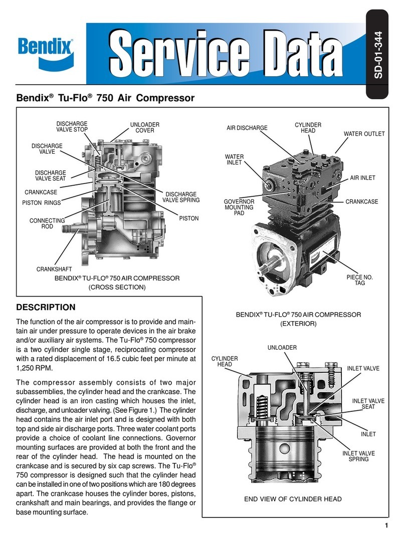
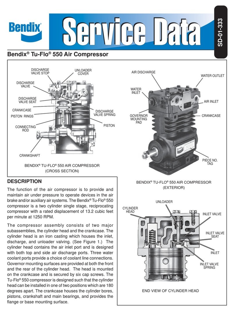
Cylinder Head
Removethe six cylinderhead capscrews andtap the head
withasoft mallettobreak thegasket seal. Removethe inlet
valvespringsfromtheheadandinletvalvesfromtheirguides
in the crankcase. Remove inlet valve guides from around
the inlet valve seats on the crankcase taking care not to
damage seats. Scrape off any gasket material from the
cylinderheadand crankcase.Unscrew the dischargevalve
seats from the head and remove the discharge valves and
springs.Inspectthe discharge valveseats for nicks,cracks,
and excessive wear and replace if necessary.
The discharge valve stops should be inspected for wear
and replaced if excessive peening has occurred. To
determineif excessivepeening has occurred, measure the
dischargevalvetravel.Dischargevalvetravelmustnotexceed
.057inches.Toremove thedischarge valve stops, support
themachinedsurfaceofthecylinderhead on anarborpress
bedandgently pressthestops fromthe top ofthe head and
outthe bottom.Be sureto allow sufficient clearance for the
stopsbetween the pressbed andthe bottom ofthe cylinder
head. The valve stop bores in the cylinder head must be
inspectedfor excessivescoring.Anewhead body must be
used if scoring is excessive. Discard the inlet valves and
springs,thedischargevalvesandspringsandthe discharge
valveseatsifdefective.
Crankcase Base Plate or Adapter
Remove the cap screws securing the base plate or base
adapter.Tapwithsoftmallettobreak the gasket seal. Scrape
offany gasket materialfromcrankcaseandplateor adapter.
Connecting Rod Assemblies
(Note: Before removing the connecting rods, mark each
connectingrod andits cap. Each connecting rod is
matched to its own cap for proper bearing fit, and
these parts must not be interchanged.)
Straighten the prongs of the connecting rod bolt lock strap
and remove the bolts and bearing caps. Push the piston
withtheconnectingrodsattachedoutthetopofthecylinders
of the crankcase. Replace the bearing caps on their
respective connecting rods. Remove the piston rings from
the pistons. If the pistons are to be removed from the
connecting rods, remove the wrist pin lock wires or teflon
plugs and press the wrist pins from the pistons and
connectingrods.
Ifthe pistonsare removed from the rod,inspect the bronze
wrist pin bushing. Press out and replace the bushing if it is
excessively worn. (See inspection of Parts) Discard the
piston rings and the connecting rod journal bearings.
Discard the wrist pin bushings if they were removed.
Crankcase
Removethe keyor keys from the crankshaftand any burrs
fromthe crankshaftwhere the key or keys were removed.
(Note: ThroughDriveCompressorsmayhaveacrankshaft
key at both ends.)
Removethefourcapscrewssecuring front ordrive-endend
coverorflange adapter.Removethe endcover,takingcare
notto damagethe crankshaft oil seal or front mainbearing,
if any. Remove both of the small seal rings from the
crankcase,and the o-ring from around the frontend cover.
Remove the four cap screws securing the rear end cover
and remove the rear end cover taking care not to damage
therearmain bearing,if any.Removeboth of thesmall seal
ringsfromthecrankcaseandtheo-ring from aroundtheend
cover.Ifthe compressorhas ball typemain bearings,press
the crankshaft and ball bearings from the crankcase, then
press the ball bearings from the crankshaft. Remove the
unloader spring, spring saddle, and spring seat from the
inletcavityofthecrankcase,usinglongnosepliers.Remove
theunloaderplungersandguides.Covertheinletcavitywith
ashoprag andapply air pressureto the governormounting
pad unloader port to blow the unloader pistons out of their
bores and into the inlet cavity.
CLEANING OF PARTS
General
All parts should be cleaned in a good commercial grade
solvent and dried prior to inspection.
Cylinder Head
Removeallthe carbondepositsfrom thedischarge cavities
and all the rust and scale from the cooling cavities of the
cylinder head body. Scrape all the foreign matter from the
body surfaces and use shop air pressure to blow the dirt
particles from all the cavities.
Crankcase
Clean the carbon and dirt from the inlet and unloader
passages. Use shop air pressure to blow the carbon and
dirtdeposits from theunloader passages.
Oil Passages
Thoroughly clean all oil passages through the crankshaft,
crankcase, end covers, and base plate or base adapter.
Inspect the passages with a wire to be sure. Blow the
loosenedforeign matterout withair pressure.
