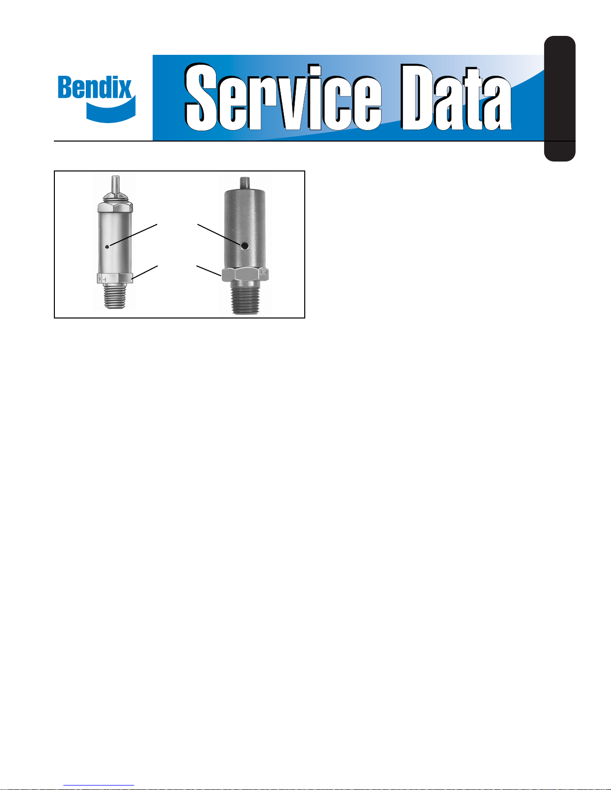
BENDIX ST-1 ST-3 SAFETY VALVE User manual
Other BENDIX Control Unit manuals

BENDIX
BENDIX R-6 RELAY VALVE User manual

BENDIX
BENDIX QR-N QUICK RELEASE VALVE User manual

BENDIX
BENDIX AR-2 ANTILOCK RELAY VALVE User manual

BENDIX
BENDIX TC-2 TRAILER CONTROL BRAKE VALVE User manual

BENDIX
BENDIX MV-1 MODUTROL Service manual

BENDIX
BENDIX RV-4 PRESSURE REDUCING VALVE Operating and maintenance instructions

BENDIX
BENDIX R-12V User manual

BENDIX
BENDIX RE-4 RELAY EMERGENCY VALVE User manual

BENDIX
BENDIX BP-R1 BOBTAIL PROP RELAY VALVE User manual

BENDIX
BENDIX TP-3DC TRACTOR PROTECTION VALVE User manual

BENDIX
BENDIX QRN-2 QUICK RELEASE VALVE User manual

BENDIX
BENDIX DUAL RELAY VALVE User manual

BENDIX
BENDIX PP-DC PARK CONTROL VALVE User manual

BENDIX
BENDIX R-8R ELAY VALVE User manual

BENDIX
BENDIX MV-2 CONTROL MODULE User manual

BENDIX
BENDIX SS-1 SHUT OFF VALVE User manual

BENDIX
BENDIX RV-3 PRESSURE REDUCING VALVE Operating and maintenance instructions

BENDIX
BENDIX E-7 DUAL BRAKE VALVE User manual

BENDIX
BENDIX SR-5 TRAILER SPRING BRK VALVE User manual

BENDIX
BENDIX TW-2 User manual


Popular Control Unit manuals by other brands

Festo
Festo Compact Performance CP-FB6-E Brief description

Elo TouchSystems
Elo TouchSystems DMS-SA19P-EXTME Quick installation guide

JS Automation
JS Automation MPC3034A user manual

JAUDT
JAUDT SW GII 6406 Series Translation of the original operating instructions

Spektrum
Spektrum Air Module System manual

BOC Edwards
BOC Edwards Q Series instruction manual

KHADAS
KHADAS BT Magic quick start

Etherma
Etherma eNEXHO-IL Assembly and operating instructions

PMFoundations
PMFoundations Attenuverter Assembly guide

GEA
GEA VARIVENT Operating instruction

Walther Systemtechnik
Walther Systemtechnik VMS-05 Assembly instructions

Altronix
Altronix LINQ8PD Installation and programming manual