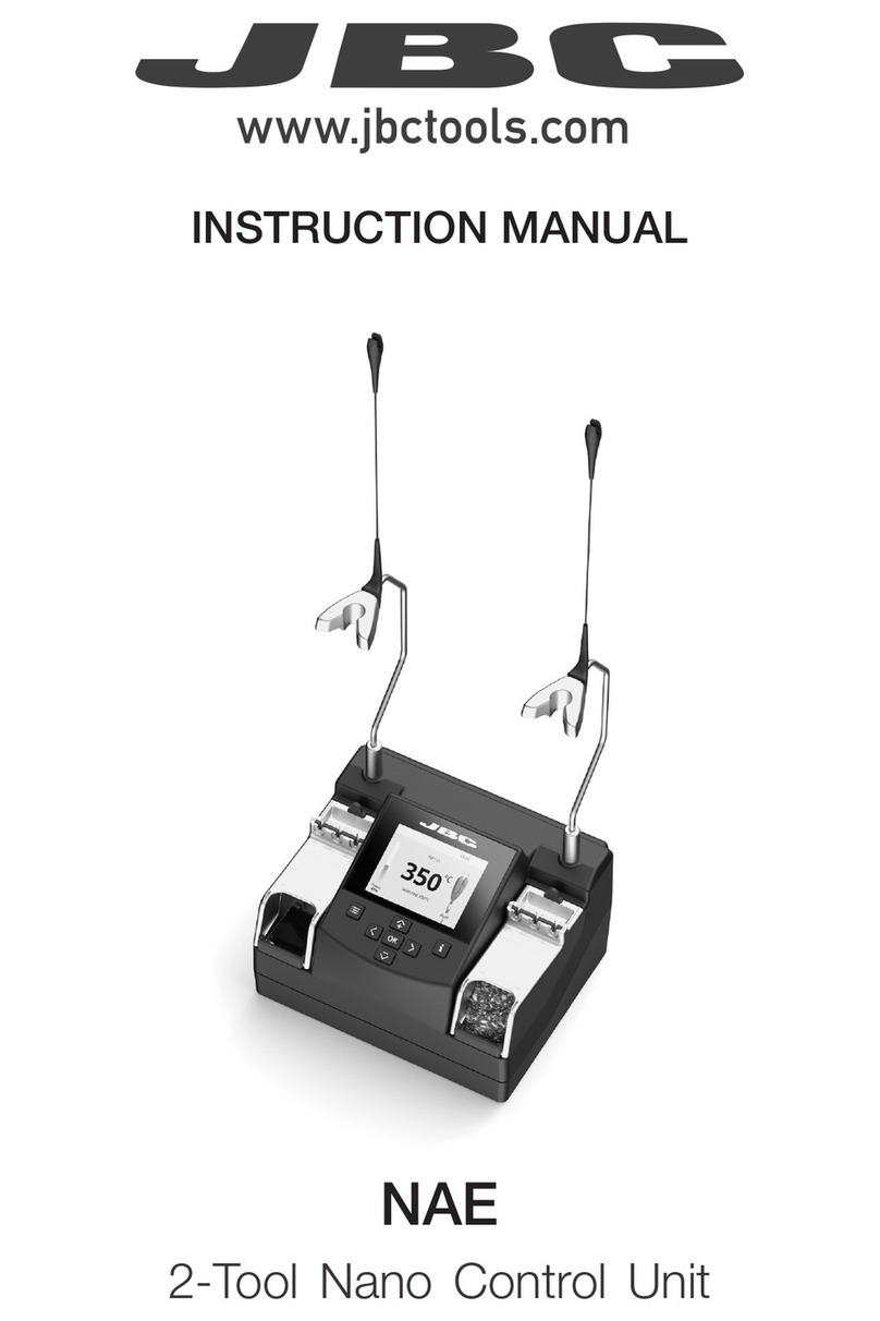
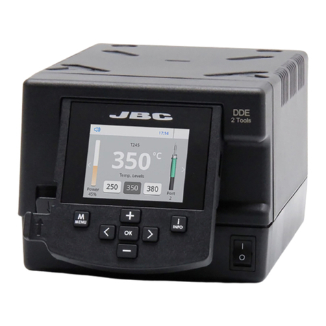
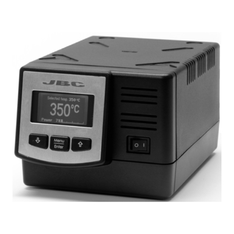
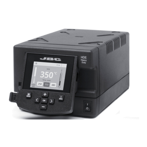
jbc DDE-1B User manual

English 2
Page
Two-Tool Control Unit
Ref. DDE-B
Español 12
Deutsch 22
中文 32
www.jbctools.com

2
Packing List
The following items should be included:
Features
Two-Tool
Control Unit .................... 1 unit
Ref. DDE-1B (120V)
DDE-2B (230V)
DDE-9B (100V)
Power Cord ..................... 1 unit
Ref. 0010569 (230V)
0013671 (100/120V)
Manual ...............................1 unit
Ref. 0016160
USB-A connector
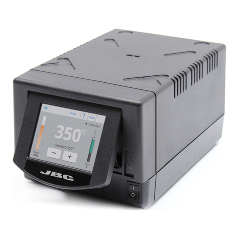
2,8” Color TFT screen
Tilt the display
for easy reading
Two-Tool Control Unit
Ref. DDE-B
www.jbctools.com

3
Connections
Work simultaneously with
up to 2 tools and 1 module
+ 1 pedal for each tool
(Peripherals).
Peripherals
Stand
DDE Control Unit
RJ12 connector
for Robot system
USB-B
connector
Equipotential
connection
Power Socket
Compatibility
* The MNE Nitrogen Flow Regulator is required.
**If you need to connect the MS, MV, MN or FS modules, an adapter is required (Ref. IM2496).
Select the equipment that best suit your soldering or desoldering needs.
Basic working system Peripherals**
Control
Unit Stand Tool Cartridge
Range
MSE-A /
MVE-A MNE-A FSE-A P-005
DDE-B
AD-SD
T210-A C210
T245-A C245
T470-A C245
DN-SE
T210-NA* C210
T245-NA* C245
T470-NA*
AP-SD AP250-A C250
PA-SD PA120-A C120
HT-SD HT420-A C420
DS-SD DS360-A C360
DR-SD DR560-A C560
www.jbctools.com

350ºC
Port
2
Power
45%
T245
17:14
Selected 350ºC
Port
2
T245
17:14
Sleep
Tool in the stand
Actual Temp. 180ºC
Delay to hibernation: 29:30 Port
2
T245
17:14
Hibernation
Actual Temp. 25ºC
4
3. Hibernation
Operation
The JBC Exclusive Heating System
Our revolutionary technology is able to recover tip temperature extremely quickly. It means the user
can work at a lower temperature and improve the quality of soldering. The tip temperature is further
reduced thanks to the Sleep and Hibernation modes which increase the tip life by 5.
1. Work 2. Sleep
When the tool is lifted from the
stand the tip will heat up to the
selected temperature.
When the tool is in the stand,
the temperature falls to the
preset sleep temperature.
After longer periods of
inactivity, the power is cut off
and the tool cools down to
room temperature.
Tools Menu:
· Set temperature limits
· Select temperature levels
Tools Menu:
· Set Sleep temperature
· Set Sleep delay
(from 0 to 9 min or no Sleep)
Tools Menu:
· Set Hibernation delay
(from 0 to 60 min or no
hibernation)
Long time
in the stand

350ºC
Port
2
Power
45%
Temp. Levels
T245
250 350 380
17:14
5
Menu Options
Station
Information
Tool
in use
Work Screen
Status bar
Change
port
Displayed if
temperature
levels are
activated
Station Tools Counters
ResetGraphicsPeripherals
Press INFO for each parameter description. USB flash drive is connected.
Station is controlled by a PC.
Station is controlled by a robot.
Station software update.
Press INFO to start the process.
Warning.
Press INFO for failure description.
Error. Press INFO for failure description,
the type of error and how to proceed.
System notifications (Status Bar)
Power
indicator
The DDE offers an intuitive user interface which provides quick access to station parameters.
Original PIN: 0105
www.jbctools.com

Port 1 - T245
450
400
350
300
250
150
100
50
200
Power Temp
17:14
6
By pressing Graphics in the main MENU, temperature and power figures in real
time are displayed for each port. This helps you decide which tip to use to obtain
the best quality solder joints.
Process analysis
Graphics
Temperature
Power (%)
Export graphics
Insert a USB flash drive into the USB-A connector
to save your soldering process in csv format.
See other
port graphic

7
Soldering Net
Remotely manage and monitor as many stations as your PC can handle.
Functions:
- Set all the station parameters from your PC.
- Organize groups of stations and set all their parameters at the same time.
- Store specific configurations for later uses.
- Analyze the soldering graphics of the stations on your PC and export them.
1. Download the JBC Manager software and the user manual from
www.jbctools.com/manager.html
2. Connect the stations via USB-B connector and the PC will automatically detect them.
3. The notification will be displayed on the station.
any JBC
station
JBC
Manager
software
USB Hub
www.jbctools.com

8
1. Connect the tool to the station port by means of the CHB-A Converter.
2. Connect your Robot system to the Robot connector (RJ12) of the station.
DB9-RJ12 Adapater available only if necessary (Ref: 0013772).
3. Enable the Robot option in the station settings and the notification will be displayed:
4. Set your Robot’s commands according to the Robot Communication Protocol, available on the
website www.jbctools.com/jbcsoftware-menu-115.html
Manage and monitor the station using a Robotic system.
Working with Robots
Update the station software
1. Download the JBC Update File from
www.jbctools.com/software.html and save
it on a USB flash drive. Preferably one with no
other files.
2. Insert the USB flash drive to the station.
The icon is diplayed while updating.
Control
Unit
Robot
RS-232
connection
JBC
Update File
CHB-A
Converter
Ref. CHB-A

9
Maintenance
- Use a damp cloth to clean the casing and the
tool. Alcohol can only be used to clean the
metal parts.
- Periodically check that the metal parts of the
tool and stand are clean so that the station
can detect the tool status.
- Maintain tip surface clean and tinned prior to
storage in order to avoid tip oxidation.
Rusty and dirty surfaces reduce heat transfer
to the solder joint.
- Periodically check all cables and tubes.
Fuse holder
Fuse holder
Fuse
1. Pull off the fuse holder and remove the
fuse. If necessary use a tool to lever it off.
2. Press the new fuse into the fuse holder
and replace it in the station.
- Replace a blown fuse as follows:
- Replace any defective or damaged pieces. Use original JBC spare parts only.
- Repairs should only be performed by a JBC authorized technical service.
Clean periodically
Before carrying out maintenance or storage, always allow the equipment to cool.
- Clean the station screen with a glass cleaner or a damp cloth.
www.jbctools.com

It is imperative to follow safety guidelines to prevent electric shock, injury,
fire or explosion.
10
- Do not use the units for any purpose other than soldering or rework. Incorrect use may cause fire.
- The power cord must be plugged into approved bases. Be sure that it is properly grounded
before use. When unplugging it, hold the plug, not the wire.
- Do not work on electrically live parts.
- The tool should be placed in the stand when not in use in order to activate the sleep mode.
The soldering tip, the metal part of the tool and the stand may still be hot even when the station
is turned off. Handle with care, including when adjusting the stand position.
- Do not leave the appliance unattended when it is on.
- Do not cover the ventilation grills. Heat can cause inflamable products to ignite.
- Avoid the contact of flux with skin or eyes to prevent irritation.
- Be careful with the fumes produced when soldering.
- Keep your workplace clean and tidy. Wear appropriate protection glasses and gloves when
working to avoid personal harm.
- Utmost care must be taken with liquid tin waste which can cause burns.
- This appliance can be used by children over the age of eight and also persons with reduced
physical, sensory or mental capabilities or lack of experience provided that they have been given
adequate supervision or instruction concerning use of the appliance and understand the hazards
involved. Children must not play with the appliance.
- Maintenance must not be carried out by children unless supervised.
Safety

11
Specifications
DDE-1B120V 50/60Hz. Input fuse: 4A. Output: 23,5V.
DDE-2B230V 50/60Hz. Input fuse: 2A. Output: 23,5V.
DDE-9B100V 50/60Hz. Input fuse: 5A. Output: 23,5V.
- Weight: 3,815 kg (8.41 lb)
- Dimensions: 148 x 120 x 232 mm (5.8 x 4.7 x 9.1 in)
- Output Peak Power: 150W per tool
- Temperature Range: 90 - 450 °C (190 - 840 °F) (±5%)
- Idle Temp. Stability (still air): ±1.5 ºC / ±3 ºF
- Tip to ground resistance: <2 ohms
- Tip to ground voltage: <2mV RMS
- Ambient operating temp: 10 - 40 ºC (50 - 104 ºF)
- Connections USB-A / USB-B / Peripherals connectors
RJ12 connector for Robot
Complies with CE standards.
ESD protected.
www.jbctools.com

12
Two-Tool Control Unit
Ref. DDE-B
Composición
Los siguientes artículos deben estar incluídos
Características
Two-Tool Control Unit
Unidad de control DDE..... 1 u.
Ref. DDE-1B (120V)
DDE-2B (230V)
DDE-9B (100V)
Power Cord
Cable de red ............. 1 unidad
Ref. 0010569 (230V)
0013671 (100/120V)
Manual ...............................1 unit
Ref. 0016160
Conector USB-APantalla de color TFT de 2,8”
Incline la pantalla
para una mejor lectura
www.jbctools.com

13
Conexiones
Trabaje simultáneamente con
2 herramientas y enlace cada
puerto con 1 módulo
+ 1 pedal (Peripherals).
Periférico
Soporte
Unidad de control DDE
Conector RJ12
para Robot
Connector USB-B
Conexión
equipotencial
Toma de correinte
Compatibilidades
* Se requiere el Regulador de Flujo de Nitrógeno MNE
**Si necesita conectar los módulos MS, MV, MN or FS, se requiere de un adaptador (Ref. IM2496).
Seleccione los equipos que más se adapten a sus necesidades de soldadura
Sistema de trabajo básico Periféricos / Módulos**
Unidad de
control soporte Herramienta Gama de
cartuchos
MSE-A /
MVE-A MNE-A FSE-A P-005
DDE-B
AD-SD
T210-A C210
T245-A C245
T470-A C245
DN-SE
T210-NA* C210
T245-NA* C245
T470-NA*
AP-SD AP250-A C250
PA-SD PA120-A C120
HT-SD HT420-A C420
DS-SD DS360-A C360
DR-SD DR560-A C560
www.jbctools.com

350ºC
Port
2
Power
45%
T245
17:14
Selected 350ºC
Port
2
T245
17:14
Sleep
Tool in the stand
Actual Temp. 180ºC
Delay to hibernation: 29:30 Port
2
T245
17:14
Hibernation
Actual Temp. 25ºC
14
3. Hibernación
Funcionamiento
El exclusivo sistema calefactor de JBC
Nuestra tecnología revolucionaria es capaz de recuperar la temperatura de la punta de forma
extremadamente rápida. Esto significa que el usuario puede trabajar a una temperatura más baja
y mejorar la calidad de la soldadura. Esta temperatura se reduce aún más gracias a los modos de
Sleep e Hibernation que incrementan hasta 5 veces la vida de las puntas.
1. Trabajo 2. Sleep
Cuando se levanta la
herramienta del soporte, la
punta se calentará hasta la
temperatura seleccionada.
Si la herramienta permenece
en el soporte, la temperatura
se reduce a la temperatura
predefinida.
Tras largos períodos de
inactividad (predefinido a
30min), se corta el suministro
de energía y la punta se enfría
hasta temperatura ambiente.
Tools Menu:
· Configure límites de
temperatura.
· Seleccione niveles de
temperatura.
Tools Menu:
· Configure la temperatura
de Sleep
· Configure el tiempo de
retraso de Sleep
(de 0 a 9 min o ninguno)
Tools Menu:
· Configure el retraso de
Hibernación
(de 0 a 60 min o ninguno)
Períodos
largos en el
soporte

350ºC
Port
2
Power
45%
Temp. Levels
T245
250 350 380
17:14
15
Unidad de memoria USB conectada.
Estación controlada por un PC.
Estación controlada por un robot.
Actualización del software de la esta-
ción. Pulse INFO para iniciar el proceso.
Aviso.
Pulse INFO para la descripción del fallo.
Error. Pulse INFO para la descripción del
fallo, el tipo de error y cómo proceder.
Notificaciones (Barra de estado)
Opciones de Menú
Pantalla de trabajo
La DDE-B presenta una interfaz de usuario intuitiva y ofrece un rápido acceso a los parámetros.
PIN Original: 0105
Station Tools Counters
ResetGraphicsPeripherals
Pulse INFO para la descripción de parámetros.
Ayuda de la
estación
Indicador
de potencia
Herramienta
en uso
Barra
de estado
Cambio de puerto
Se muestra si
los niveles de
temperatura
están activos
www.jbctools.com

Port 1 - T245
450
400
350
300
250
150
100
50
200
Power Temp
17:14
16
Pulsando sobre Graphics en el menú principal, se muestran las respuestas de
temperatura y potencia en tiempo real de cada puerto. Esto le ayudará a decidir
cuál es la punta más adecuada para obtener la mejor calidad en sus soldaduras.
Análisis del proceso
Exporte gráficos
Inserte una unidad de memoria USB para
guardar su proceso de trabajo en formato csv.
Graphics
Temperatura
Potencia (%)
Vea el gráfico
del otro puerto

17
Red de soldadura
Remotely manage and monitor as many stations as your PC can handle.
Funciones:
- Configure todos los parámetros de la estación desde su PC.
- Organice grupos de estaciones y configure todos sus parámetros al mismo tiempo.
- Guarde configuraciones específicas para usos posteriores.
- Analice gráficos del proceso de soldadura de las estaciones desde su PC y expórtelos.
1. Descargue el software JBC Manager y el manual de usuario de
www.jbctools.com/manager.html
2. Conecte las estaciones a través del conector USB-B y el PC las detectará automáticamente.
3. La notificación se mostrará en la estación.
cualquier
estación JBC
JBC
Manager
software
USB Hub
www.jbctools.com

JBC
Update File
Convertidor
CHB-A
Ref. CHB-A
18
1. Conecte la herramienta a la estación utilizando el convertidor CHB-A (Ref: CHB-A).
2. Conecte su sistema robotizado al conector Robot de la estación (RJ12).
Si lo necesita, el adaptador DB9-RJ12 está disponible (Ref: 0013772).
3. Active la opción de robot en la estación y se mostrará la siguiente notificación:
4. Configure su sistema robotizado según el Protocolo de Comunicación para Robots,
que encontrará en www.jbctools.com/jbcsoftware-menu-115.html.
Gestione y monitorice la estación por medio de un sistema robotizado.
Trabajar con Robots
Actualice el software de la estación
1. Descargue el archivo de actualización de
www.jbctools.com/software.html
cuando esté disponible y guárdelo en una
unidad de memoria USB (preferentemente
una sin otros archivos).
2. Inserte la unidad de memoria USB.
La notificación se muestra mientras
se actualiza el software.
Unidad de
control
Robot
Conexión
RS-232

19
Mantenga limpio
Mantenimiento
Antes de realizar tareas de mantenimiento o almacenar, desconecte el equipo y déjelo enfriar.
- Clean the station screen with a glass cleaner or a damp cloth.
- Use un paño húmedo para limpiar la
pantalla del equipo, la carcasa y la
herramienta. Puede utilizar alcohol
solamente en las partes metálicas.
- Compruebe periódicamente que las partes
metálicas de la herramienta y del soporte
están limpias. Así la estación puede
detectar el estado de la herramienta y
activar los modos de Sleep o Hibernation.
- Mantenga la punta limpia y estañada la
para evitar su oxidación. Las superfícies
sucias reducen la transferencia térmica a la
soldadura.
- Revise periódicamente los tubos y cables.
Portafusible
Portafusible
Fusilble
1. Tire del portafusible para retirar el fusible.
Si lo precisa, utilice una pequeña palanca.
2. Sustituya el fusible y coloque de nuevo el
portafusibles en su sitio.
- Cambie el fusible fundido de la siguiente manera:
- Cambie cualquier pieza defectuosa o dañada. Utilice solamente recambios originales de JBC.
- Cualquier reparación sólo se podrá realizar por un servicio técnico oficial JBC.
www.jbctools.com

Es necesario cumplir estas normas de seguridad para prevenir cualquier
choque eléctrico, heridas, fuego o explosiones.
20
- No utilice el equipo para otros fines que no sea la soldadura o reparación. El uso incorrecto
puede causar fuego.
- El cable de red debe enchufarse en bases homologadas. Asegúrese de que está conectado a
tierra correctamente antes de su uso. Al retirarlo, tire del conector, no del cable.
- No trabaje con tensión.
- La herramienta debe permanecer en el soporte mientras no está en uso con el fin de activar el modo
de Sleep o Hibernación. El cartucho y las partes metálicas de la herramienta o del soporte pueden
estar calientes incluso cuando con la estación apagada. Manipule con cuidado, incluso cuando se
ajusta la posición del soporte.
- No deje el aparato desatendido cuando está en funcionamiento.
- No cubra las rejillas de ventilación. El calor puede causar que los productos inflamables se enciendan.
- Evite el contacto del Flux con la piel o los ojos para prevenir la irritación.
- Tenga cuidado con el humo producido al trabajar.
- Mantenga su lugar de trabajo limpio y ordenado. Use gafas y guantes de protección adecuados.
Así evitará cualquier daño.
- Tenga cuidado con los restos de estaño líquido. En contacto con la piel, puede causar quemaduras.
- Este aparato puede ser utilizado por personas a partir de 8 años y también por aquellas
personas con movilidad reducida o capacidades físicas, sensoriales o mentales limitadas o
con falta de experiencia y conocimientos siempre y cuando reciban supervisión o instrucciones
relativas al uso del aparato de una manera segura y entiendan los riesgos que implica. Los niños
no deben jugar con el aparato.
- Los niños no deberán realizar tareas de mantenimiento sin supervisión.
Seguridad
This manual suits for next models
2
Table of contents
Languages:
Other jbc Control Unit manuals
Popular Control Unit manuals by other brands

Siemens
Siemens Simatic S7-300 manual

Belimo
Belimo Z2050QPT-D quick start guide

Graff
Graff IMMERSION 2150250 Instructions for assembly and use

Honeywell Home
Honeywell Home D15S installation instructions

Raspberry Pi
Raspberry Pi 52PI-RPI-UART user manual

SMC Networks
SMC Networks JSXF Series Operation manual

Siemens
Siemens QPA228.FWNC Series Operator Interface Guide

Soca
Soca ST-320 Operation and installation manual

Jetter
Jetter JX3-THI2-TC-EI user manual

Symmons
Symmons Temptrol VersaFlex S262BODY installation instructions

Bosch
Bosch Professional GCY 42 Original instructions

GuitarPCB
GuitarPCB Emerald Ring manual