Beninca BULL 10M User manual

L8542351
12/2008 rev2
BULL5M
BULL8M
UNIONE NAZIONALE COSTRUTTORI
AUTOMATISMI PER CANCELLI, PORTE
SERRANDE ED AFFINI


3
1
2
4
140
330
326
330
260
210
B
100
325
XA
92
83
3
5
D
R
T
T2
=
=
75
300
max 20mm
24mm
60

4
6 7
98
≈1 mm
P
D
V
C
D
R
10
P
V
C
11
34 mm
BULL.P3
68 mm 103 mm
C

5
12
13
AS
1 ÷ 3 cm
G
F
CL
OK

6
8
7
4
1
2
3
3 x 1,5 min
2 x 1,5
RG 58
5
4 x 0,35
230V
4
6
5
2 x 0,35
3 x 0,35
H
14

7
изготовитель: Automatismi Benincà SpA.
Адрес: Via Capitello, 45 - 36066 Sandrigo (VI) - Italia
Декларирует, что: автоматизация для cдвижных ворот модели BULL 5M - 8M.
• изготовлена для включения в конструкцию или сборки с другим оборудованием для того чтобы составить машину, считаемую по
директиве 89/392 CE, как модифицированную;
• таким образом не соответствует по всем пунктам этой директиве;
• соответствует условиям следующих директив CE:
Директива низких напряжений 73/23/CEE, 93/68/CEE.
Директива электромагнитой совместимости 89/336/CEE, 93/68/CEE.
и кроме того объявляет что не разрешено вводить в эксплутацию оборудование до того как машина, в которой оно включено или
явлается компонентом, была определения и декларирована соответствующей условиям директивы 89/392 CE и соответствующим
местным нормати.
Benincà Luigi, Управляющий.
Sandrigo, 10/06/2008.
Привод должен быть установленный квалифицированным
персоналом по действующим нормативам.
Конечный потребитель не интересуется этими
сообщениями.
Держать инструкции для будущих использований.
Установщик должен снабжать информацией, что
касается автоматического, ручного и чрезвычайного
функционирования автоматизация и отдать инструкции по
эксплуатации пользователю оборудования.
mОд н о п оляр н ы й вк л ючатель с р а с с т о я н и ю
открывания контактов равным или выше 3 мм -
обязательно установить в питании. Проверять что
в электрооборудования находится дифференциальный
включатель и защитный включатель из-за перегрузочного
тока. Некоторые типы установок требуют подключение створки
оборудованию заземления по действующим нормативам
безопаности.
Электропроводка и логика фунционирования должны
соответствоватьдействующим нормативам.
Целесообразно прокладывать силовые кабели (двигатель,
питание) отдельно от управляющих (кнопки, фотоэлементы,
радио), или должны быть адекватно изолированы с
дополнительной изолацией по крайней мере 1 мм.
Кабели должны дополнительно крепится при входе/выходе
из монтажный коробок.
Обьязательно удалить питание перед установки,
эксплуатации и ремонта.
Вновь проверить все подключения, прежде чем давать
напряжение.
Неиспользуемые входы Н.З. (обычно замкнутый) должны
быть перемкнуты.
Оставляя без изменений основных характеристик данного
продукта, производитель оставляет за собой право вносить
любые технические, коиструктивные и коммерческие
изменения без обязаться обновить инструкции.

8
Поздравляем Вас с выбором привода BULL.
Все изделия широкого ассортимента Beninca являются
плодом двадцатилетнего опыта в области автоматических
управлений и непрерывного поиска новых материалов и
авангардных технологий.
Именно поэтому, сегодня мы способны предложить
крайнее надежные изделия, которые, благодаря их
мощности, эффективности и долговечности, способны
полностью удовлетворить потребности конечного
потребителя.
Все наши изделия изготовлены в соответствии с
действующих нормативами и покрыты гарантией.
Кроме того, полис гражданской ответственности
заключенный с первичной страховой компанией
покрывает возможные убытки предметам или лицам,
причиненные дефектами изготовления.
Автоматизация с однофазный питанием 230 В для
сдвижных ворот, два варианты:
BULL 5M для ворот с весом макс 500 кг
BULL 8M для ворот с весом макс 800 кг
BULL моноблок с утонченным дизайном и уменьшенными
размерами; состоит из алюминиевого модуля, содержащего
двигатель и систему нереверсивного редуктора,
изготовленную из высокопрочных материалов. BULL
имеет пружинный конец хода. Аварийная деблокировка
персонализированным ключом позволяет передвижение
ворот вручную при перебоях питания.
Безопасность антисдавливания гарантируется
электронным устройством (энкодер), обнаруживающим
возможные препятствия.
Для правильного функционирования сдвижной
автоматизации, автоматизируемые ворота должны
отвечать следующим требованиям:
- направляющая и соответствующие ролики должны быть
надлежащих размеров и надлежаще обслуживаться
(чтобы избегать чрезмерного трения при движении
ворот);
- в течение функционирования дверь не должна
производить чрезмерные колебания;
- ход открытия и закрытия должен быть ограничен
механическими упорами (согласно действующим
нормативам безопасности).
BULL 5M BULL 8M
Питание 230Vac 50Hz
Потребляемая мощность 235 W 280 W
Ток 1,3 A 1,5 A
Усилие 18 Nm 25 Nm
Рабочий цикл 40%
Класс защиты IP54
Класс изоляции F
Рабочая температура -20°C / +70°C
Сонденсатор 12,5 μF 16 μF
Макс. вес ворот 500kg 800kg
Зубчатая рейка M4
Скорость открытия 10,5 m/min 10,5 m/min
Щумность <70 dB
Смазка CASTROL OPTITEMP LP2
Вес 10,6 kg 11,4 kg
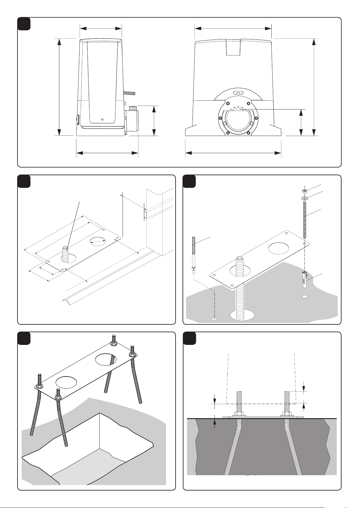
Габаритные Размеры привода в мм.
Необходимо соблюдать расстояние от зубчатой рейки
Рис. 2, два варианты:
X = 52 мм для зубчатой рейки из нейлона
X = 49 мм для зубчатой рейки из стали 12х30 мм
Предусмотреть трубку (рис. 2-А) для кабелей питания и
подключения принадлежностей.
управлять, что в конце установки базовая пластина
совершенно параллельна створке.
Используя пластину как шаблон, сверлить 4 отверстия
Ø 10 мм.
посредством 4 болтов с анкерами “T” закрепить на земле
базовую пластину использовая 4 крючки М8х150мм “В” и
гайки “D” и шайбы “R”.
Продается алтернативные системы крепления как
например расшириенные пробки (рис.3-Т2) которые
вставятся с помоьщю молоточных ударов.
В этом случае, после изготовления правильный котлован,
сагнуть брусоки с резьбой как показано в рис. 4.
Вмуровать крючки в бетон, соблюдая горизонтальность
и уровень пластины.
Ждать затвердения бетона фундамента.
В рис. 5 законченная установка базовой пластины.
.
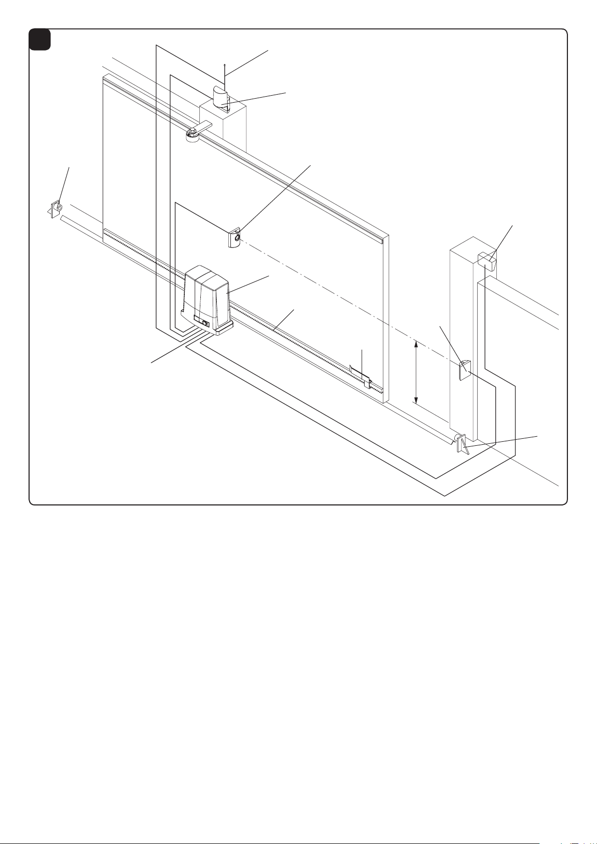
Позиционировать зубчатую рейку на высоте 68 мм от оси
втулки до плоскости установки базовой плиты; в таком
положении сверлить и нарезать резьбу M6.
Соблюдать шаг зуба Р между концами зубчатых реек; с
этой целью удобно использовать еще одну зубчатую рейку

9
как шаблон (см. Рис. С).
Позиционировать крепежные втулки D и приварить или
привернуть их на плотне ворот на высоте 103 мм от оси
втулки до плоскости установки базовой плиты.
Затем закрепить зубчатую рейку, соблюдая указания
пунктов 4.3 и 4.4.
Соблюдать шаг зуба Р между концами зубчатых реек; с
этой целью удобно использовать еще одну зубчатую рейку
как шаблон (см. Рис. С).
Закрепить зубчатую рейку с помоьшю винты V.
Внимание: между зубачтой рейкой и шестернем нужно
около 1 мм (см. Рис. 8); в этом случае помогать себя с
плетицами.
Позиционировать привод в базовой пластины шестерней
относительно зубчатой рейки.
Деблокировать автоматизацию и проверять, что вставка
правильно в польном ходе зубчатой рейки. Возможно
регулировать оложения рейки с помоьшю плиетницы.
Блокировать привод на основие и закрепить сильно 4
гайки D с шайбами R. Приложить два картеры С.
В случае зубчатая рейка уже установлена в положении
выше чем зубчатом колесе, возможно поднять пластину
(макс. 20 мм) постав гайки и шайбы под пластину (см.
рис. 10).
Если обеспечение кабелей полключения не позволяет
крепление стандартное крепление, свободна
допонительная пластина BULL.P3 (рис. 11) которая
позволяет поднять прибизытельно 34 мм расстояние
установки привода помагая переход кабелей.
Вручную сдвинуть ворота до механического упора в
открытии A и отодвинуть назад на 1 - 3 см, в зависимости
от веса ворот; затем позиционировать скобу конца хода S
на грани срабатывания концевого микровыключателя
и зафиксировать гайкой G. Повторить аналогично для
закрытия.
Прим.: скоба конца хода должна быть размещена
так, чтобы позволять остановку ворот без удара по
механическому ограничителю хода.
Чтобы использовать ворота вручную, произведите
деблокировку следующим образом:
- вставив ключ C, поверните его по часовой стрелке и
потяните рычаг L;
- привод деблокирован - возможно двигать вручную
полотно ворот;
- для возврата к нормальному функционированию,
закройте рычаг L и двигайте ворота вручную до
блокировки.
Для электромонтажа автоматизации и для регулировки
функционирования, см. инструкции к блоку управления.
.
Рис 10 указывает подключения для стандартную
установку. Перед тем как пропустить кабеля, уточнить
правильный тип подключения для использованных
принадлежностей.
Расстояние H - высота установки фотоэлементов,
советуем устоновить расстояние с 40 до 60 см.
Легенда:
1 Привод с встроенным блоком управления BULL
2 Зубчатая рейка M4 Nylon/Fe
3 Скоба конца хода
4 Фотоэлемент
5 Механический упор
6 Ключевой переключатель или цифровая
клавиатури
7 Сигнальная мигающая лампа
8 Антенна
Полис страхования от возможных убытков предметам
или лицам, вызванных дефектами изготовления, требует
соответствие установки действующим нормативам и
использование оригинальных компонентов Benincà.

10
EC Declaration of Conformity regarding machines
(Directive 89/392 CE,Annex II B) - No servicing
Manufacturer: Automatismi Benincà SpA.
Address: Via Capitello, 45 - 36066 Sandrigo (VI) - Italia
We herewith declare that: the automatic system for sliding gates, BULL 5M - 8M model.
• is intended to be incorporated into a machine or assembled together with other devices to form a machine in compliance with the
EC Directive 98/37, as amended;
• therefore, is not in every respect complying with this Directive;
• is complying with provisions set forth by the following other EC Directive:
EC Low voltage Directive (73/23/EEC, 93/68/EEC).
EC Directive of Electromagnetic Compatibility (89/336/EEC, 93/68/EEC)
Moreover, we herewith declare that the system shall not be put into service until the machine in which the same will be incorporated
or of which it will become a component, is acknowledged compliant with the EC Directive 98/73 and applicable national legislation
and a related declaration of conformity is drawn up. In other words, no servicing shall be carried out until the system under this
declaration does not form one single nal machine with other components.
Benincà Luigi, Legal responsible.
Sandrigo, 10/06/2008.
The product shall not be used for purposes or in ways
other than those for which the product is intended for and
as described in this manual. Incorrect uses can damage
the product and cause injuries and damages.
The company shall not be deemed responsible for the
non-compliance with a good manufacture technique of
gates as well as for any deformation, which might occur
during use.
Keep this manual for further use.
Qualified personnel, in compliance with regulations in force,
shall install the system.
Packaging must be kept out of reach of children, as it can
be hazardous. For disposal, packaging must be divided
the various types of waste (e.g. carton board, polystyrene)
in compliance with regulations in force.
The installer must supply all information on the automatic,
manual and emergency operation of the automatic system
and supply the end user with instructions for use.
WARNING
mAn omnipolar switch/section switch with remote
contact opening equal to, or higher than 3mm
must be provided on the power supply mains..
Make sure that before wiring an adequate differential
switch and an overcurrent protection is provided.
Pursuant to safety regulations in force, some types of in-
stallation require that the gate connection be earthed.
During installation, maintenance and repair, cut off power
supply before accessing to live parts.
Descriptions and figures in this manual are not binding.
While leaving the essential characteristics of the product
unchanged, the manufacturer reserves the right to modify
the same under the technical, design or commercial point
of view without necessarily update this manual.

11
INTRODUCTION
Congratulations on your choice of a BULL gear motor.
All items included in Benincà’s wide product range stem
from twenty year of our experience in the sector of automatic
systems, always striving to find new materials and advanced
technologies.
For this reason, nowadays we are able to offer you extremely
reliable products that, thanks to their power, efficiency and
long-lasting features, entirely meet the end user’s require-
ments.
All our products are covered by a guarantee.
Furthermore, an R.C. insurance policy signed with a primary
insurance company, covers any injuries or damages caused
by manufacturing faults.
GENERAL INFORMATION
This automatic system, with 230Vac single-phase power sup-
ply for sliding gates, is available in the following versions:
BULL 5M for gates with maximum weight equal to 500kg
BULL 8M for gates with maximum weight equal to 800kg
BULL is a monobloc system featuring a refined design and
reduced dimensions. The motor and an irreversible reduction
system, manufactured with high resistant materials, are hou-
sed in an aluminium container. BULL is equipped with spring
limit switches. The customised key emergency release allows
to open and close the gate in case of power failure.
Anti-crash safety is ensured by an electronic device (enco-
der and amperometric sensor) which detects any obstacle
present.
PRELIMINARY CHECKS
For a good operation of the automatic system for sliding
gates, the gate or door shall meet the following features:
- the track and relevant wheels must feature correct sizes
and must undergo adequate maintenance (in order to avert
excessive friction during the sliding of the gate).
- during operation, the door shall not excessively oscillate.
- a mechanical stopper (according to regulations in force)
shall limit the opening and closing movements.
SPECIFICATIONS
BULL 5M BULL 8M
Power supply 230Vac 50Hz
Power drawn 235 W 280 W
Current drawn 1,3 A 1,5 A
Torque 18 Nm 25 Nm
Work jogging 40%
Protection level IP54
Insulation Class F
Operating temperature -20°C / +70°C
Capacitor 12,5 μF 16 μF
Gate max. weight 500kg 800kg
Rack module M4
Opening speed 10,5 m/min 10,5 m/min
Noise <70 dB
Lubrication CASTROL OPTITEMP LP2
Weight 10,6 kg 11,4 kg
INSTALLATION
FIG.1
Overall dimensions of the gear motor expressed in mm.
POSITIONING OF THE FOUNDATION PLATE
FIG.2-3-4-5
It is very important to keep to dimension X shown in Fig.2.
This value depends on the type of rack used:
X = 52 mm for rack in nylon
X = 49 mm for rack in iron, 12x30mm
Preset a corrugated tube (Fig.2 -A) for the passage of power
supply cables and connection wires for the accessories.
Check that, at the end of the fitting, the foundation plate is
perfectly parallel with respect to the wing.
Fit the system with screw anchors on the bottom of the
cement (Fig.3).
Drill 4 holes, diam.10mm, by using the foundation plate as
drilling template.
Tightly anchor the foundation plate to ground through the
4 “T” steel screw anchors and the 4 “B” threaded bars,
M8x150mm and corresponding “D” nuts and “R” washers.
Alternative fitting systems are available on the market, e.g.
anchoring with retaining expansion band (Fig.3 -T2) to be
inserted in the hole with some hammer strokes.
Fitting to be cemented (Fig.4)
In this case, after providing an adequate foundation hole,
bend the threaded bars as shown in Fig.4.
Submerse the bars in cement, paying attention to the level
of the plate.
Wait that the cement hardens.
Fig. 5 shows the completed fitting plate.
Regardless of the type of fitting, check that the threaded
bars are firmly anchored to ground and that they protrude
for at least 24mm (44 mm for raised installation).
FITTING OF THE RACK
FIG.6-7-8
Rack in nylon (Fig.6).
Position the rack at a height of 68 mm from the centre line of
the fixing slot provided on the base on which the foundation
plate will be fitted. At that height, drill a hole on the gate and
provide for a M6 threading.
Keep to the P tooth pitch, even from a section of rack and
another. To this purpose, it could be useful to join another
section of rack (Part. C)
Rack in Fe 12x30mm (Fig.7).
Position the spacers D by welding them or fitting them with
screws to the gate, at 103 mm height from the centre line
of the fixing slot provided on the base on which the founda-
tion plate will be fitted. Fix the rack by following points 4.3
and 4.4.
Keep to the P tooth pitch, for all sections of the rack. To
this purpose, it could be useful to connect another section
of rack (Part. C)
Then fix the rack with V screws, taking care, once the actua-
tor is installed, that 1-mm backlash is left between the rack
and the tow wheel (seei Fig.8). To this purpose, use the slots
on the rack.
POSITIONING AND ANCHORING OF THE ACTUATOR
FIG.9-10
Position the gear motor on the foundation plate with the gear
centred with respect to the rack.
Release the automatic system and check that the gear be

12
correctly positioned along the entire stroke of the rack. If
required, adjust the alignment by using the special slots.
Fix the gear motor to the base by firmly tightening the 4 nuts
D and inserting the R.
Apply the two screw covers C.
If the rack is already installed in a position which is higher
than the pinion, the plate can be raised (20 m maximum) by
moving the nuts and the washers under the plate, as shown
in Fig.10.
If the connecting cables already present make it difficult to
fix the standard plate, the optional plate BULL P3 (Fig. 11)
can be used, thus allowing to raise the actuator installation
by about 34 mm and facilitating the passage of cables.
POSITIONING OF THE LIMIT SWITCH BRACKETS
FIG.12
Manually open the gate and leave a clearance from 1 to
3cm according to the weight of the gate between the main
door and the mechanical stopper A. Fix the bracket to the
limit switch S by using the grains G, so that the limit switch
microswitch F is pressed. The same operation should be
repeated with gate in the closing phase.
N.B.: The limit switch bracket should be positioned so that
the gate can be stopped without hitting the mechanical
stopper.
MANUAL OPERATION
FIG.13
Should a power failure or malfunction occurs, to manually
operate the gate proceed as follows:
- After inserting the customised key C, turn it anti-clock-
wise and pull the lever L.
- The gear motor is unlocked and the gate can be
moved by hand.
- To return to the normal operating mode, close the
lever L again and manually activate the gate until it is
geared.
WIRE DIAGRAM
FIG.14
For the wire connections of the system and to adjust the
operating modes, please refer to the Instruction Manual of
the control unit.
In particular, the anti-crash device (encoder) should be
adjusted according to regulations in force.
Please remember that the device should be earthed by
means of the appropriate terminal.
Fig.10 shows wiring for a standard installation. Before
proceeding to wiring, check that the type of cables used is
consistent with those required for accessories.
Dimension H stands for the installation height of photocells.
A clearance between 40 and 60 cm is advisable.
Key of components:
1 Gear motor with incorporated BULL control unit
2 M4 rack, Nylon/Fe
3 Limit switch brackets
4 Photocells
5 Mechanical stoppers
6 Key selector or digital keyboard
7 Flashing light
8 Antenna
WARNING
The RC product insurance policy, which covers any injuries
or damages to objects caused by manufacturing defects,
requires the use of Benincà’s original accessories.

13
• Не находиться в зоне движения створок.
• Не позволять детям играть с управлением или поблизости от створок.
• В случае неисправного и/или ненормального функционирования не пытаться исправлять
самостоятельно, но вызвать технического специалиста.
Чтобы использовать ворота вручную, произведите деблокировку следующим образом:
- вставив ключ C, поверните его по часовой стрелке и потяните рычаг L;
- привод деблокирован - возможно двигать вручную полотно ворот;
- для возврата к нормальному функционированию, закройте рычаг I и двигайте ворота вручную до
блокировки.
• Периодически контролировать эффективность ручной деблокировки.
• Безусловно воздерживаться от попытки самостоятельного ремонта и/или обслуживания во избежание
травм и/или поломок; для этих операций вызовите технического специалиста.
• Привод не требует повседневного обслуживания, но все же необходимо проверять периодически
эффективность защитных устройств и других частей установки, которые могут создавать опасности
вследствие износа.
По окончании срока эксплуатации утилизуйте изделие принятым в вашей стране образом, что касается
дифференцированной переработки и рециклирования выпустил компоненты (металлы, пластмассы,
электрические провода и так далее); целесообразно консультироваться с Вашим установщиком или
специализированной и уполномоченной фирмой.
Полис страхования от возможных убытков предметам или лицам, вызванных дефектами изготовления,
требует соответствие установки действующим нормативам и использование оригинальных компонентов
Benincà.
BULL
CL

14
BULL
SAFETY MEASURES
• Donotstandwithinthegatemovementarea.
• Childrenmustnotplaywithcontrolsandnearthegate.
• Intheeventofmalfunctions,donotattempttorepairthefailurebutcontactthespecialisedpersonnel.
MANUAL AND EMERGENCY MANOEUVRE
In the event of power failure or malfunction, to manually operate the gate proceed as follows:
• AfterinsertingthecustomizedkeyC,turnitanti-clockwiseandpulltheleverL.
• Thegearedmotorisunlockedandthegatecanbemovedbyhand.
• Toreturntothenormaloperatingmode,closetheleverLagainandmanuallyactivatethegateuntilitisgeared.
MAINTENANCE
•Everymonthcheckthegoodoperationoftheemergencymanualrelease.
•Itismandatorynottocarryoutextraordinarymaintenanceorrepairsasaccidentsmaybecaused.Theseoperations
must be carried out by qualified personnel only.
•Theoperatorismaintenancefreebutitisnecessarytocheckperiodicallyifthesafetydevicesandtheothercomponents
of the automation system work properly. Wear and tear of some components could cause dangers.
WASTE DISPOSAL
If the product must be dismantled, it must be disposed according to regulations in force regarding the differentiated waste
disposal and the recycling of components (metals, plastics, electric cables, etc..). For this operation it is advisable to call
your installer or a specialised company.
WARNING
All Benincá products are covered by insurance policy for any possible damages to objects and persons caused by con-
structionfaultsunderconditionthattheentiresystembemarkedCEandonlyBenincápartsbeused.
USER’S HANDBOOK
CL

Ref. BULL 5M
Code Note
1
9686445
2
9686420
3
9686328
4
9686329
5
9686332
6
9686421
7
9686447
8
9686424
9
9686032
10
9686426
11
9686427
12
9686449
13
9686448
Ref. BULL 8M
Code Note
1
9686446
2
9686420
3
9686328
4
9686329
5
9686332
6
9686421
7
9686447
8
9686424
9
9686032
10
9686426
11
9686427
12
9686449
13
9686448
4
13
1
3
12
5
6
7
2
11
10
8
9

AUTOMATISMI BENINCÀ SpA - Via Capitello, 45 - 36066 Sandrigo (VI) - Tel. 0444 751030 r.a. - Fax 0444 759728
Other manuals for BULL 10M
7
This manual suits for next models
1
Table of contents
Languages:
Other Beninca Engine manuals

Beninca
Beninca JM.3 ESA User manual

Beninca
Beninca BEN User manual

Beninca
Beninca DU.350N User manual

Beninca
Beninca AU.96L SPAZIO Installer manual

Beninca
Beninca AU.45 Installer manual

Beninca
Beninca BISON 20 OM User manual

Beninca
Beninca AU.45L Installer manual

Beninca
Beninca BULL 1224 TURBO User manual

Beninca
Beninca BULL 424 User manual

Beninca
Beninca YAK 20 OM Series User manual