Tormach ATC User manual

TECHNICAL DOCUMENT Version 0718A
Owner's
Guide:770M®
Automatic Tool
Changer (ATC)
Page 1
Specifications subject to change without notice.
©Tormach® 2018

1.1 PURPOSE
This document gives instructions to install and use an Automatic
Tool Changer (ATC) on a 770M®.
You must install the Power Drawbar on your machine before
installing the ATC. Do not install the Power Drawbar button (the
button's functionality is replaced by the ATC).
1.2 PRODUCT INFORMATION
Product: Automatic Tool Changer (ATC)
The Automatic Tool Changer (ATC) holds up to 10 tools in a single
tray. If your program requires more tools, the ATC changes tools
automatically for all tools assigned to the tray, and pauses for a
manual tool change for all tools not assigned to the tray.
Quantity Description PN
1 ATCAssembly —
3 Fixed Standoff Assembly 37260
10 Plastic Screw 32173
1 Tilt Standoff Assembly 35911
NOTE: If any of these items are missing, we can help.
Email support@tormach.com to contact Tormach
Technical Support for guidance on how to proceed.
Page 2
©Tormach® 2018
Specifications subject to change without notice.
tormach.com
TD10427: Owner's Guide: 770M Automatic Tool Changer (0718A)
TECHNICAL DOCUMENT

2.1 SETTING UP THE AUTOMATIC TOOL CHANGER (ATC)
2.1.1 Required Tools
This procedure requires the following tools. Make sure that you
have them available before you begin.
Tools Required for Installation
l1-1/2 inch adjustable wrench
lMetric hex wrench set
lPhillips screwdriver
lSmall, flat-head screwdriver
lSnips
lSocket wrench, and a 13 mm socket
Tools Required for Validation
lMachinist's square
l8-inch rod for Tormach Tooling System® (TTS®) tool holder
lTormach Tooling System® (TTS®) tool holder
2.1.2 Air Requirements
You must make sure that the site conforms to the following air
supply requirements.
lAir Pressure. Between 90 pounds per square inch (psi) and
120 psi (620 kPa - 825 kPa).
If the air supply is more than 120 psi (825 kPa), you must
use a regulator.
lDry Air. We recommend using a compressed air dryer,
desiccator, or filter between the air compressor and the
machine.
lLubricated Air. You must lubricate the air with air tool oil.
Use the FRLFilter-Regulator-Lubricator (PN 38829) or
similar for this purpose.
2.1.3 Prepare the Machine
1. If there is already a Tormach Tooling System® (TTS®) tool
holder in the spindle, remove it.
2. From the PathPilot® interface, reference the mill: click Ref Z,
Ref X, and Ref Y.
WARNING! Electrical Shock Hazard: You must
power off the machine before making any
electrical connections. If you don't, there's a risk of
electrocution or shock.
3. Power off the machine and the PathPilot® controller.
a. Push in the Emergency Stop button on the operator box,
which disables movement of the axes and the spindle.
b. From the PathPilot® interface, click Exit.
c. Turn the Main Disconnect switch to Off on the side of the
electrical cabinet.
2.1.4 To Install the Automatic Tool Changer (ATC)
Installing the ATC involves the following steps. Complete them in
the order listed:
lStep 1: "Disassemble the Power Drawbar Button" (below)
lStep 2: "Install the Air Cylinder" (on the next page)
lStep 3: "Mount the Automatic Tool Changer (ATC) Bracket"
(on the next page)
lStep 4: "Install the Main Assembly" (page5)
lStep 5: "Level the Automatic Tool Changer (ATC)" (page5)
lStep 6: "Make Air Connections" (page7)
lStep 7: "Make Electrical Connections" (page8)
lStep 8: "Validate the Installation" (page8)
lStep 9: "Adjust the Power Drawbar" (page8)
Disassemble the Power Drawbar Button
If you previously installed the Power Drawbar button assembly,
you must first disassemble it.
If you're installing an Automatic Tool Changer (ATC) on a new
machine, go to "Mount the Automatic Tool Changer (ATC) Bracket"
(on the next page).
1. Disconnect shop air supply from the machine, and then
disconnect all air lines from the Power Drawbar button.
2. Set aside the shop air line for later installation.
3. Remove four M5 × 0.8 - 10 button head cap screws that
secure the Power Drawbar button cover.
4. Remove two M4 × 0.7 - 50 socket head cap screws that
Page 3
©Tormach® 2018
Specifications subject to change without notice.
tormach.com
TD10427: Owner's Guide: 770M Automatic Tool Changer (0718A)
TECHNICAL DOCUMENT
secure the Power Drawbar button to the spindle head.
5. Remove the Power Drawbar button from the spindle head.
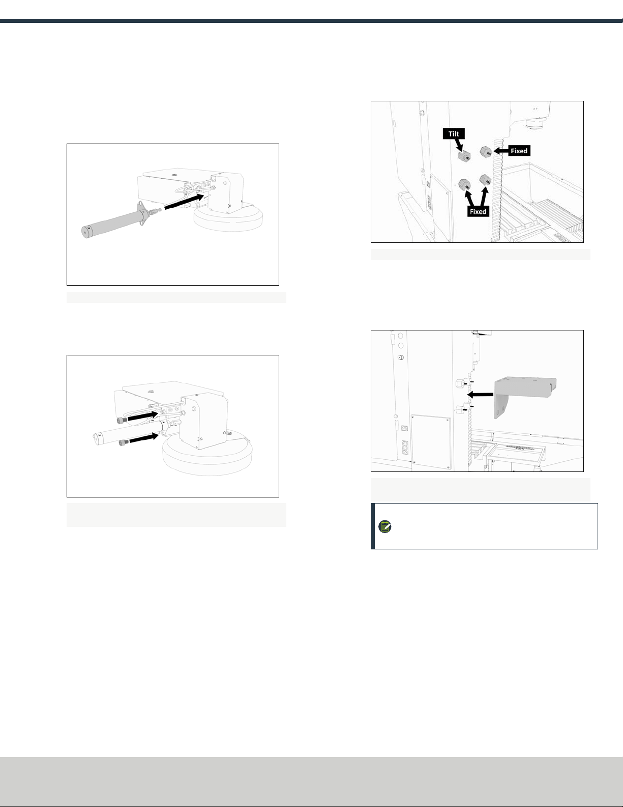
Install the Air Cylinder
1. Insert the air cylinder into the ATC main assembly.
Figure 2-1: Air cylinder aligned with the ATC main assembly.
2. Use a 12 mm hex wrench (provided) to secure the air
cylinder to the ATC main assembly with two M14 × 20 mm
socket head cap screws.
Figure 2-2: Air cylinder hardware aligned with the air
cylinder.
3. Connect the airlines from the ATC main assembly to the air
cylinder.
Mount the Automatic Tool Changer (ATC) Bracket
1. Identify four provided standoffs, used to mount the ATC to
the Z-column:
lThree fixed standoffs
lOne tilt standoff
2. Remove the flange nut and the washer from each standoff.
3. Set aside all flange nuts and washers.
4. Install the four standoffs on the Z-column in the order
shown in the following image.
Figure 2-3: Four standoffs installed on the Z-column.
5. Tighten the standoffs securely on the Z-column using an
adjustable wrench.
6. Install the ATC mounting bracket on the standoff's threaded
studs as shown in the following image.
Figure 2-4: ATC mounting bracket installed on the four
standoffs.
NOTE: Make sure that the tilt standoff's eccentric
cam fits into the large slot on the ATC mounting
bracket.
Page 4
©Tormach® 2018
Specifications subject to change without notice.
tormach.com
TD10427: Owner's Guide: 770M Automatic Tool Changer (0718A)
TECHNICAL DOCUMENT
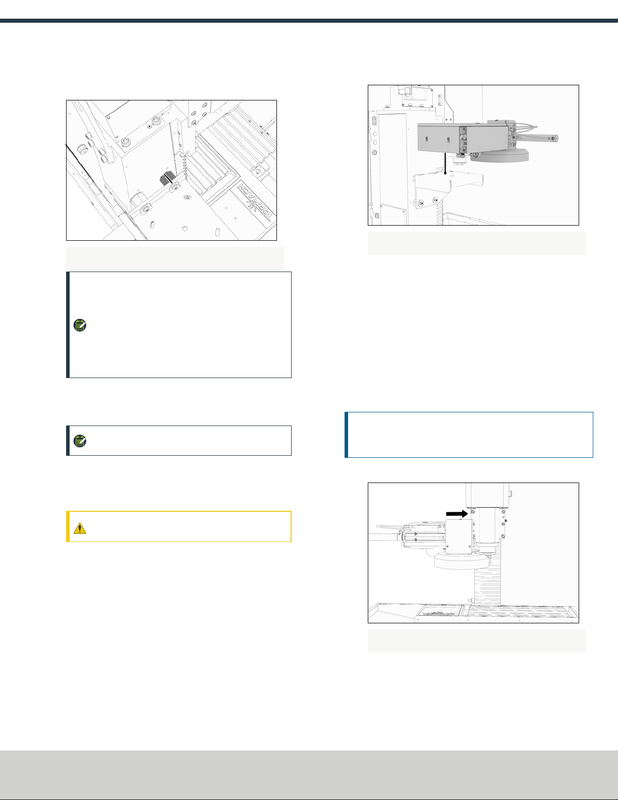
7. Make sure that the top right standoff is centered within the
slot on the ATC mounting bracket.
Figure 2-5: Example of the top right standoff centered within
the ATC mounting bracket slot.
NOTE: To make sure that the ATC mounting bracket
stays in place, you can put a piece of tape on both
the top right standoff and the slot on the ATC
mounting bracket, and draw a straight line
between them. This may help with further
adjustments made later in the installation
procedure.
8. Loosely reinstall the washers and flange nuts that you
removed in Step 3. Only tighten the washers and flange nuts
finger-tight.
NOTE: More adjustments are made later in the
installation procedure.
Install the Main Assembly
1. Identify the four provided M8 × 1.25 - 16 mm socket head
cap screws and washers, and then set them all aside.
CAUTION! Team LiftRequired: You must use two
people to lift and install the ATC on the Z-column.
2. Lift the ATC main assembly on to the mounting bracket.
Figure 2-6: ATC main assembly lifted on to the mounting
bracket.
3. Align the locating pin on the ATC main assembly with the
matching hole in the mounting bracket.
4. Use four M8 × 1.25 - 16 mm socket head cap screws that
you set aside in Step 1 to secure the ATC main assembly to
the mounting bracket.
Level the Automatic Tool Changer (ATC)
This section gives instructions to roughly align the ATC on the
machine by using a long, straight rod. More adjustments are made
later in the installation procedure.
NOTICE! After the initial installation, you must level the ATC.
If you don't, there's a risk of machine damage.
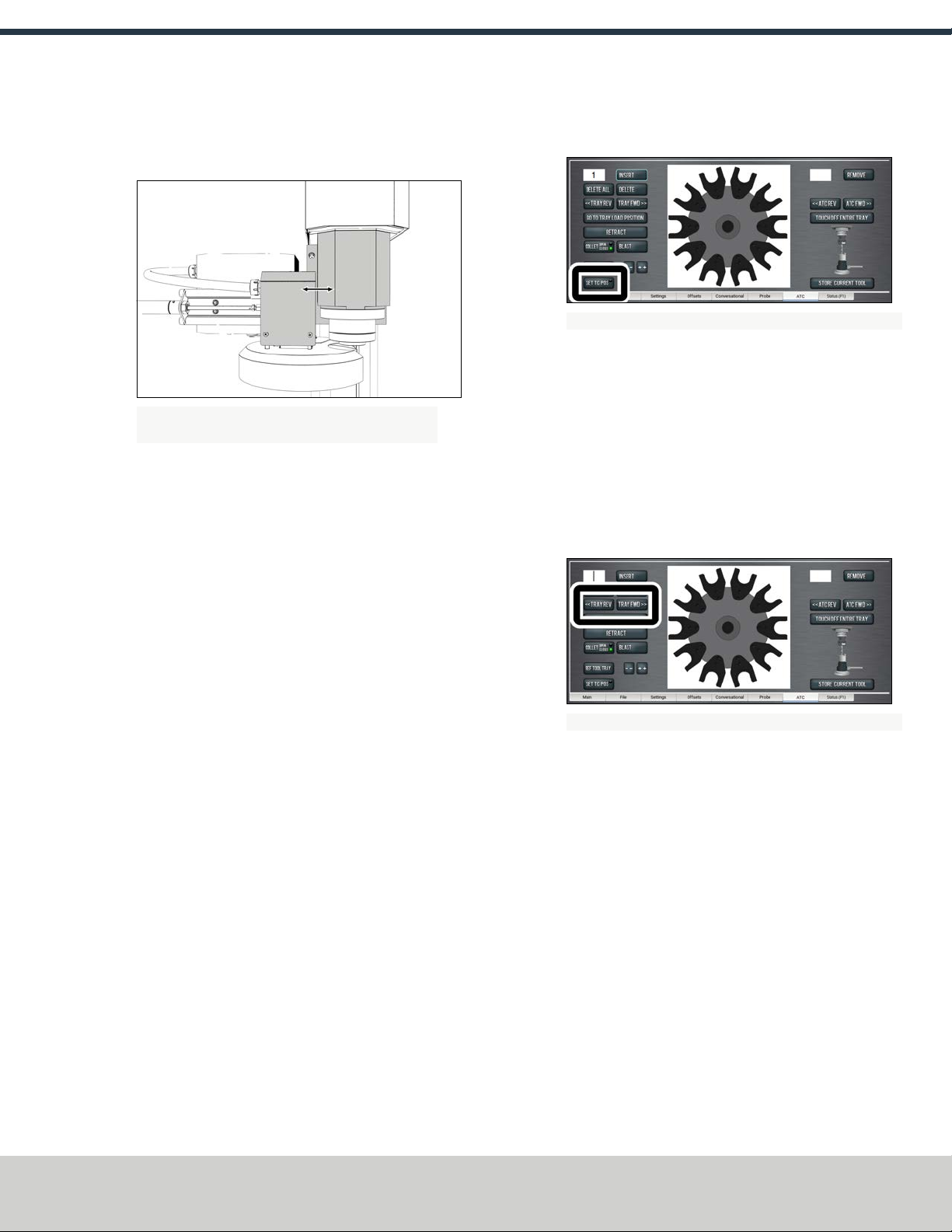
1. Move the tool tray toward the spindle.
Figure 2-7: Example of the tool tray moved in toward the
spindle.
Page 5
©Tormach® 2018
Specifications subject to change without notice.
tormach.com
TD10427: Owner's Guide: 770M Automatic Tool Changer (0718A)
TECHNICAL DOCUMENT
2. Make sure that the linear bearing on the ATC is flush with
the ATC main assembly.
Figure 2-8: Example of the linear bearing flush with the ATC
main assembly.
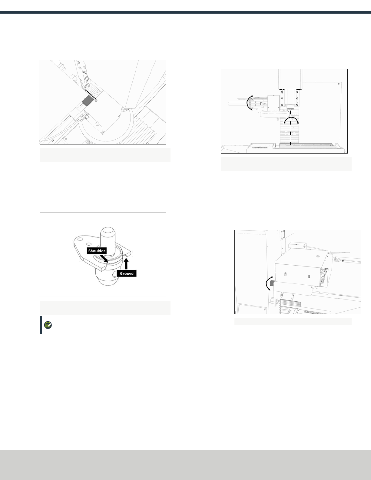
3. Insert a rod — no more than 8 inches long — into a Tormach
Tooling System® (TTS®) tool holder.
4. Insert the tool holder into the fork. Make sure that the
groove in the tool holder slides along the shoulder on the
fork.
Figure 2-9: Example of the groove on a Tormach Tooling
System® (TTS®) aligned with the shoulder of an ATC fork.
NOTE: Do not rest the tool holder on top of the
fork.
5. Put a machinist's square on the machine table. Make sure
that the rod is perpendicular to the machine table in both
the Xand the Ydirections.
Figure 2-10: Example of the directions to adjust the ATC
alignment.
If it isn't, do the following:
lAdjust the alignment of the ATC in the Ydirection:
a. Loosen the flange nuts on the standoffs.
b. Use an adjustable wrench to turn the tilt standoff, and
slowly pivot the ATC until the rod is perpendicular to
the machine table.
Figure 2-11: Tilt standoff.
c. Make sure that the top right standoff is centered
within the slot on the ATC mounting bracket.
d. Tighten the flange nuts.
e. Re-check the alignment of the ATC in the Ydirection.
Page 6
©Tormach® 2018
Specifications subject to change without notice.
tormach.com
TD10427: Owner's Guide: 770M Automatic Tool Changer (0718A)
TECHNICAL DOCUMENT

lAdjust the alignment of the ATC in the Xdirection:
a. Loosen the two socket head cap screws on the linear
rails.
Figure 2-12: Socket head cap screws on the linear
rails.
b. Slowly pivot the ATC until the rod is perpendicular to
the machine table.
c. Tighten the socket head cap screws.
d. Re-check the alignment of the ATC in the Xdirection.
Repeat this step until the rod is perpendicular to the
machine table in both the Yand the Xdirection.
6. Remove the tool holder from the fork, and then set it aside.
NOTE: You'll need this tool later in the installation
procedure to make further alignments.
7. Move the tool tray away from the spindle.
8. Power on the machine and the PathPilot® controller.
a. Turn the Main Disconnect switch to on On the right side
of the electrical cabinet.
b. Twist out the Emergency Stop button on the operator
box, which enables movement to the machine axes and
the spindle.
c. Press the Reset button on the operator box.
d. Bring the machine out of reset and reference it.
9. Slowly jog the Z-axis down (-Z) 1-1/2 inches.
10. Power off the machine and the PathPilot® controller.
a. Push in the Emergency Stop button on the operator box,
which disables movement of the axes and the spindle.
b. From the PathPilot® interface, click Exit.
c. Turn the Main Disconnect switch to Off on the side of the
electrical cabinet.
11. Move the tool tray toward the spindle.
12. Make sure that the carousel door opening is approximately
equal in distance on all sides of the spindle mounting flange.
Figure 2-13: Example of examining the distance between the
carousel door opening and the spindle mounting flange.
Figure 2-14: If it isn't, do the following:
a. Loosen the four socket head cap screws that secure the
ATC main assembly to the mounting bracket.
Figure 2-15: Socket head cap screws securing the ATC
main assembly to the mounting bracket.
b. Pivot the ATC about the locating pin in the mounting
bracket until the carousel door opening is centered with
the spindle mounting flange.
c. Tighten the socket head cap screws.
13. Move the tool tray away from the spindle.
Make Air Connections
1. Use snips to cut the zip tie securing the ATC cables and
plastic tubes together.
2. Route the loose ends of the two 1/4-inch plastic tubes
connected to the ATC main assembly through the energy
chain and toward the Power Drawbar.
Page 7
©Tormach® 2018
Specifications subject to change without notice.
tormach.com
TD10427: Owner's Guide: 770M Automatic Tool Changer (0718A)
TECHNICAL DOCUMENT
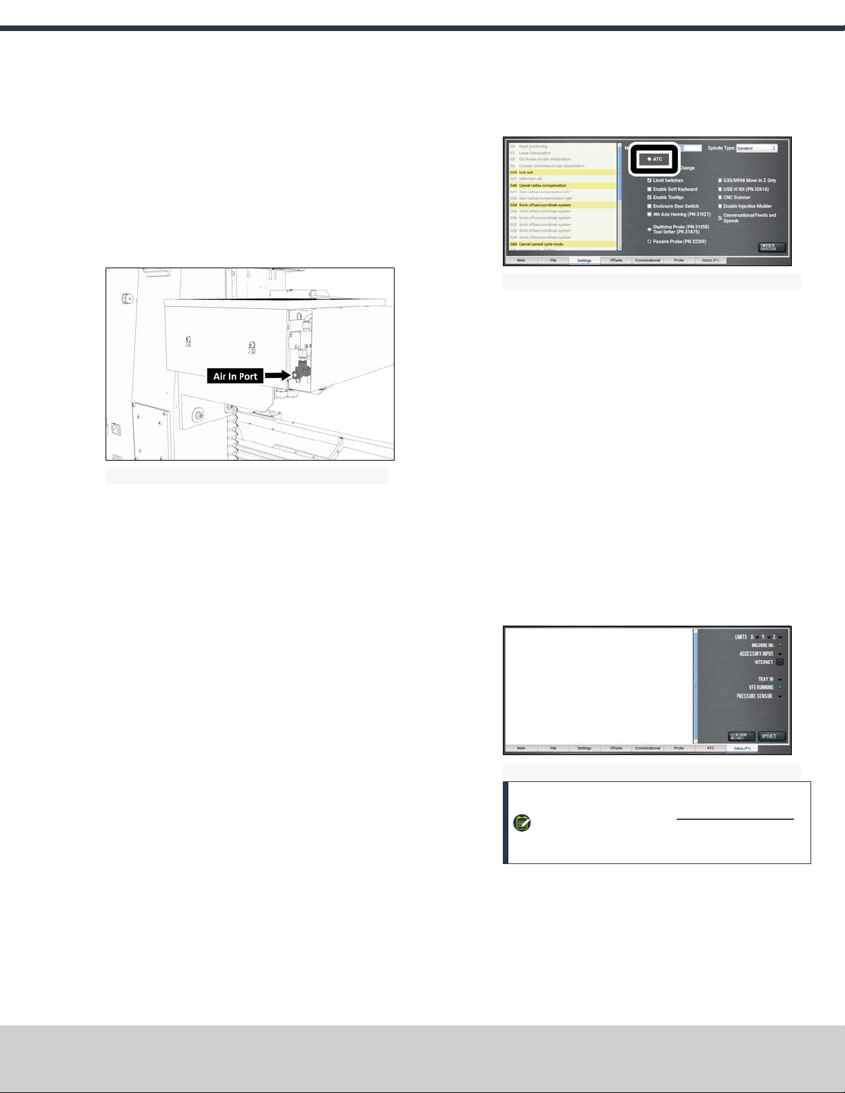
3. Connect the loose ends of the 1/4-inch plastic tubes in the
following order:
a. Connect the Retract (PDBBottom) airline to the bottom
push-to-connect elbow on the Power Drawbar.
b. Connect the Advance (PDBTop) airline to the top push-
to-connect elbow on the Power Drawbar.
c. Connect your shop's air supply to the Air In port in the
ATC main assembly.
Figure 2-16: Air In port in the ATC main assembly.
Make Electrical Connections
1. Route the ATC power cable and the USB cable toward the
back of the machine.
2. Put the USB cable in the access hole in the back of the stand
toward the controller.
3. Insert the USB cable into any open USB port on the
PathPilot® controller.
4. Connect the ATC power cable to the ATC Power connector on
the side of the electrical cabinet.
Validate the Installation
1. Power on the machine and the PathPilot® controller.
a. Turn the Main Disconnect switch to on On the right side
of the electrical cabinet.
b. Twist out the Emergency Stop button on the operator
box, which enables movement to the machine axes and
the spindle.
c. Press the Reset button on the operator box.
d. Bring the machine out of reset and reference it.
2. From the PathPilot® interface, on the Settings tab, select the
ATC radio button.
Figure 2-17: ATC radio button on the Settings tab.
The ATC tab appears in the PathPilot® interface.
3. From the Main tab, reference the machine by clicking Ref Z,
Ref X, and Ref Y.
4. Insert a tool into the spindle as follows:
a. Push and hold the button on the ATC.
The collet opens.
b. Insert a tool into the spindle.
c. Release the button.
The collet closes.
5. From the PathPilot® interface, on the Main tab, type 1000
into the RPM DRO field.
6. Click FWD.
The spindle starts.
7. From the Status tab, make sure that the VFD Running green
light comes on.
Figure 2-18: VFDRunning light on the Status tab.
NOTE: If the VFDRunning light did not come on in
Step 7, we can help. Email support@tormach.com
to contact Tormach Technical Support for guidance
on how to proceed.
8. Click Stop.
The spindle stops.
Adjust the Power Drawbar
If you have not yet done so, you must adjust the Power Drawbar.
Complete the following steps in the order listed:
Page 8
©Tormach® 2018
Specifications subject to change without notice.
tormach.com
TD10427: Owner's Guide: 770M Automatic Tool Changer (0718A)
TECHNICAL DOCUMENT
lStep 1: "Adjust the Drawbar Tension" (below)
lStep 2: "Adjust the Initial Setup" (below)
Adjust the Drawbar Tension
The purpose of this adjustment is to set the highest possible
drawbar tension while still allowing the Power Drawbar cylinder to
release the tool. For more information, go to "About Drawbar
Tension" (below).
NOTICE! After the initial installation, you must examine the
drawbar tension weekly. During periods of heavy use,
examine the drawbar tension more frequently. If you don't,
there's a risk of tool pull-out.
To adjust the drawbar tension:
1. Install an empty Tormach Tooling System® (TTS®) tool
holder in the collet.
2. Use one hand to support the tool holder, and then push the
Release Tool button. Do one of the following:
lIf the tool holder releases: Use two adjustable wrenches
to tighten the Power Drawbar in quarter-turn increments
while pushing the Release Tool button after each turn.
Stop when the tool holder does not release.
lIf the tool holder does not release: Use two adjustable
wrenches to loosen the Power Drawbar in quarter-turn
increments while pushing the Release Tool button. Stop
when the tool holder releases.
3. Make a visual reference to help you set or adjust the
drawbar tension in the future: Use a paint pen to make a
witness mark on both the head of the drawbar and the end
of the spindle.
About Drawbar Tension
While machining, the Tormach Tooling System® (TTS®) collet
holds a Tormach Tooling System® (TTS®) tool holder in the spindle
by applying a clamping force to both the shank and the shoulder of
the tool. The tension force that is applied to the drawbar pulls the
Tormach Tooling System® (TTS®) collet into the spindle taper,
which then applies the clamping force to the Tormach Tooling
System® (TTS®) tool.
The force on the drawbar, known as the drawbar tension, is
applied differently depending on the tool changing method:
lWhen you change tools manually, the tension is applied
when you tighten the drawbar into the collet using a
wrench.
lWhen you change tools with the Power Drawbar, the tension
is applied by the compressed spring washers.
Adjust the Initial Setup
The purpose of this adjustment is to make sure that there is
enough clearance between the end of the drawbar and the Power
Drawbar cylinder.
NOTICE! If you don't do this adjustment, there's a risk that
the drawbar can loosen, or that operations can be louder than
normal.
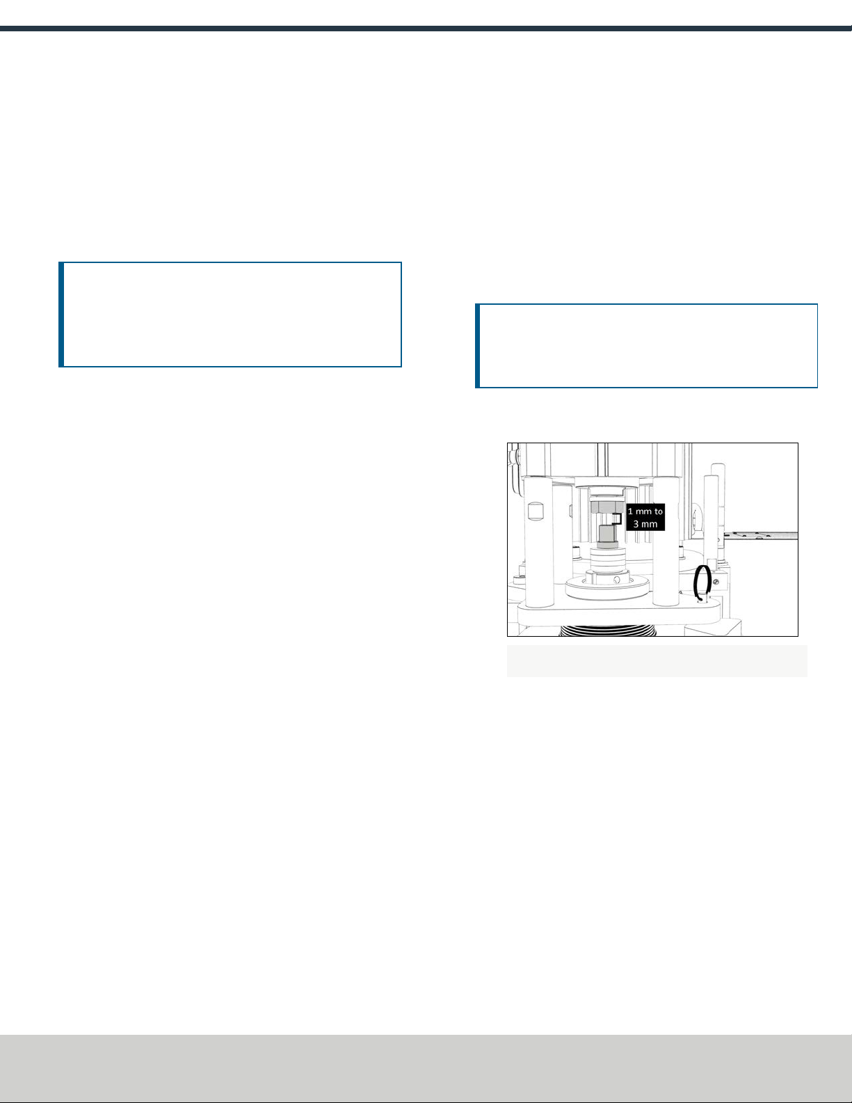
1. Examine the space between the hex head screw on the
Power Drawbar cylinder's rod and the top of the drawbar.
Figure 2-19: Example of a correctly spaced drawbar and
Power Drawbar cylinder.
2. Make sure that the gap is between 1 mm and 3 mm.
Depending on the size of the gap, do one of the following:
lIf the gap is between 1 mm and 3 mm, you have
completed adjusting the initial setup.
lIf the gap is less than 1 mm or greater than 3 mm, go to
Step 3.
3. Disconnect the shop's air supply from the Power Drawbar
button.
4. Pull out the quick-release pin.
Page 9
©Tormach® 2018
Specifications subject to change without notice.
tormach.com
TD10427: Owner's Guide: 770M Automatic Tool Changer (0718A)
TECHNICAL DOCUMENT

5. Pivot the Power Drawbar cylinder assembly to the left so
that you can access the Power Drawbar cylinder's rod.
Figure 2-20: Power Drawbar cylinder pivoted to the left.
6. Use an adjustable wrench to remove the hex head screw on
the Power Drawbar cylinder’s rod.
Figure 2-21: Hex head screw on the Power Drawbar
cylinder's rod.
7. Remove the M16 washer from the Power Drawbar cylinder’s
rod, and set it aside.
Figure 2-22: M16 washer removed from the Power Drawbar
cylinder's rod.
8. Use an adjustable wrench to reinstall the hex head screw,
and then tighten it completely.
9. Pivot the Power Drawbar cylinder to the original location.
10. Push in the quick-release pin.
11. Reconnect the shop's air supply to the Power Drawbar
button.
12. Examine the space between the hex head screw on the
Power Drawbar cylinder’s rod and the top of the drawbar.
13. Makesure that the gap is between 1 mm and 3 mm.
Depending on the size of the gap, do one of the following:
lIf the gap is between 1 mm and 3 mm, you have
completed adjusting the initial setup.
lIf the gap is less than 1 mm, go to Step 14.
14. Identify the three extra M16 flat washers provided.
15. Put one M16 flat washer under each mounting post on the
Power Drawbar cylinder.
2.1.5 To Make the Final Alignments to the Automatic
Tool Changer (ATC)
Making the final alignments the ATC involves the following steps.
Complete them in the order listed:
lStep 1: "Adjust the Tool Tray Load Position" (below)
lStep 2: "Validate the Alignment" (page12)
lStep 3: "Set the Tool Change Height" (page14)
lStep 4: "Adjust for Rotational Play" (page12)
Adjust the Tool Tray Load Position
1. Make sure that there is no tool in the spindle.
2. From the PathPilot® interface, on the ATC tab, click Ref Tool
Tray.
Figure 2-23: Ref Tool Tray button on the ATCtab.
The tool tray spins.
NOTE: You're only required to reference the tool
tray once — unlike the mill axes’ referencing
procedure.
Page 10
©Tormach® 2018
Specifications subject to change without notice.
tormach.com
TD10427: Owner's Guide: 770M Automatic Tool Changer (0718A)
TECHNICAL DOCUMENT

3. Click Go to Tray Load Position.
Figure 2-24: Go to Tray Load Position button on the ATC
tab.
4. When prompted, click OK.
The tool tray moves forward.
5. Insert the tool holder with the rod into the fork.
6. From the PathPilot® interface, slowly jog the Z-axis down (-
Z) to bring the spindle nose toward the tool in the tool tray.
7. Make sure that the tool’s shank is aligned concentrically
with the collet in the spindle. If it isn't, do the following:
lAdjust the alignment of the tool in the Ydirection
(toward or away from the Z column):
a. Determine if the tray must move clockwise or
counterclockwise.
Figure 2-25: Example of the directions to move the
tool tray.
b. From the PathPilot® interface, in the ATC tab, do one
of the following:
oClick -- to step the tool tray counterclockwise.
oClick ++ to step the tool tray clockwise.
Figure 2-26: Tool tray step buttons on the ATC tab.
Page 11
©Tormach® 2018
Specifications subject to change without notice.
tormach.com
TD10427: Owner's Guide: 770M Automatic Tool Changer (0718A)
TECHNICAL DOCUMENT
lAdjust the alignment of the tool in the Xdirection (left or
right):
a. Determine if the tray must move left or right.
Figure 2-27: Example of the directions to move the
tool tray.
b. Use two wrenches to loosen the jam nut on the end of
the cylinder rod. Make sure that you don't spin the rod
end when adjusting the jam nut.
c. Do one of the following:
oTurn the rod end one-half turn further on to the
cylinder rod to move the tool tray to the left.
oTurn the rod end one-half turn off of the cylinder
rod to move the tool tray to the right.
d. Tighten the jam nut.
Repeat this step until the tool's shank is concentric with the
collet in the spindle.
8. From the PathPilot® interface, in the ATC tab, click Retract.
Validate the Alignment
1. From the PathPilot® interface, click Go to Tray Load Position.
2. Slowly jog the Z-axis down (-Z) over the tool’s shank.
3. Make sure that the tool’s shank moves freely into the collet.
Then, do one of the following:
lIf it does not move freely in the collet, this indicates that
the ATC is misaligned and you must realign it. Go to
"Adjust the Tool Tray Load Position" (page10).
lIf it does move freely in the collet, go to "Set the Tool
Change Height" (page14).
Set the Tool Change Height
1. From the PathPilot® interface, slowly jog the Z-axis down (-
Z) over the tool. Stop jogging when the spindle nose just
makes contact with the shoulder of the tool holder.
2. On the ATC tab, click Set TC POS.
Figure 2-28: Set TCPOS button on the ATC tab.
The tool change position is set.
Adjust for Rotational Play
There is a small amount of rotational play built into the Automatic
Tool Changer (ATC) carousel. This play allows for some
misalignment during tool changes, and must be adjusted for in
both directions. The taper on the tool shank also helps align the
tool during a tool change.
1. From the PathPilot® interface, on the ATC tab, click Tray
FWD to rotate the tray clockwise (forward) one full tool slot.
Figure 2-29: Tray FWDand Tray REVbuttons on the ATCtab.
2. Click Tray REV to rotate the tray counterclockwise
(backward) one full tool slot.
3. Make sure that the tool’s shank is in line with the collet in
the spindle. Then, do one of the following:
lIf it is not in line with the collet, you must readjust the
tool tray rotation. Go to "Adjust the Tool Tray Load
Position" (page10).
lIf it is in line with the collet, you have completed the
alignment of the ATC.
Page 12
©Tormach® 2018
Specifications subject to change without notice.
tormach.com
TD10427: Owner's Guide: 770M Automatic Tool Changer (0718A)
TECHNICAL DOCUMENT
3.1 OPERATING THE AUTOMATIC TOOL CHANGER (ATC)
NOTE: Make sure that there's always a Tormach Tooling
System® (TTS®) tool holder in the collet while the
machine is not in use. Retracting the Power Drawbar to
the clamped position with no tool holder in the collet will
eventually fatigue the collet, and may shorten its service
life. For more information, refer to the Power Drawbar
documentation.
Read the following sections to understand how to operate the
ATC:
l"Assign Tool Numbers" (below)
l"Automatically Load a Tool into the Tool Tray" (below)
l"Automatically Unload a Tool From the Tool Tray" (below)
l"Insert a Tool into the Spindle" (on the next page)
l"Manually Load a Tool into the Tool Tray" (on the next page)
l"Manually Unload a Tool From the Tool Tray" (on the next
page)
l"Retrieve a Tool From the Tool Tray" (on the next page)
l"Set the Tool Change Height" (on the next page)
l"Switch to Manual Tool Changes" (page15)
3.1.1 Assign Tool Numbers
Use any tool number, from 1-256, to assign a position in the
tool tray.
3.1.2 Automatically Load a Tool into the Tool Tray
1. Load a tool into the spindle.
2. From the PathPilot® interface, on the ATC tab, type the tool
number in the Tool DRO field, and then press ENTER on the
keyboard.
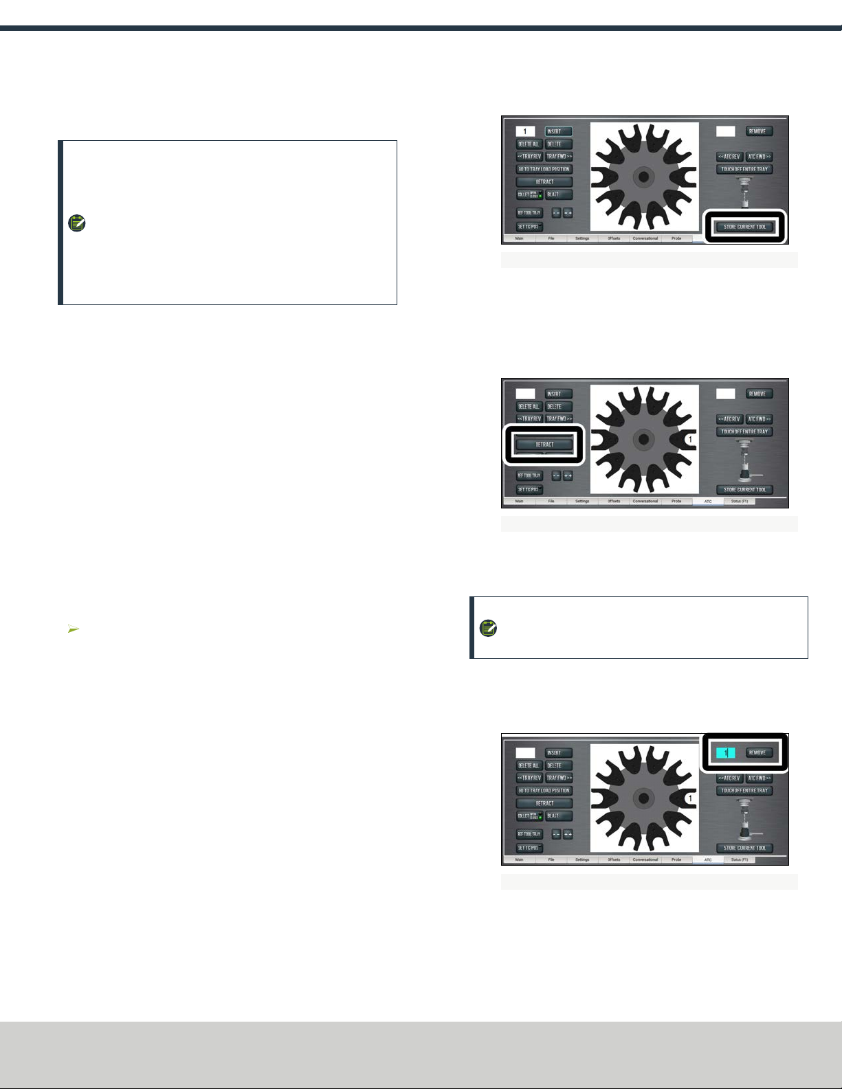
3. Click Store Current Tool.
Figure 3-1: Store Current Tool button on the ATC tab.
The tool is assigned to the nearest open slot. The ATC
fetches the tool from the spindle, and stores the tool in the
tray. The tool number is displayed on the tray image in the
center of the screen.
4. Click Retract.
Figure 3-2: Retract button on the ATC tab.
The tray returns to machining position.
3.1.3 Automatically Unload a Tool From the Tool Tray
NOTE: Typing a new tool number in the Tool DRO does
not remove the tool from its tray assignment.
1. From the PathPilot® interface, on the ATC tab, type the tool
number in the Remove DRO field, and then press ENTER on
the keyboard.
Figure 3-3: Remove DROfield on the ATC tab.
2. Click Remove.
The ATC fetches the tool from the tray.
3. Remove the tool from the spindle.
Page 13
©Tormach® 2018
Specifications subject to change without notice.
tormach.com
TD10427: Owner's Guide: 770M Automatic Tool Changer (0718A)
TECHNICAL DOCUMENT
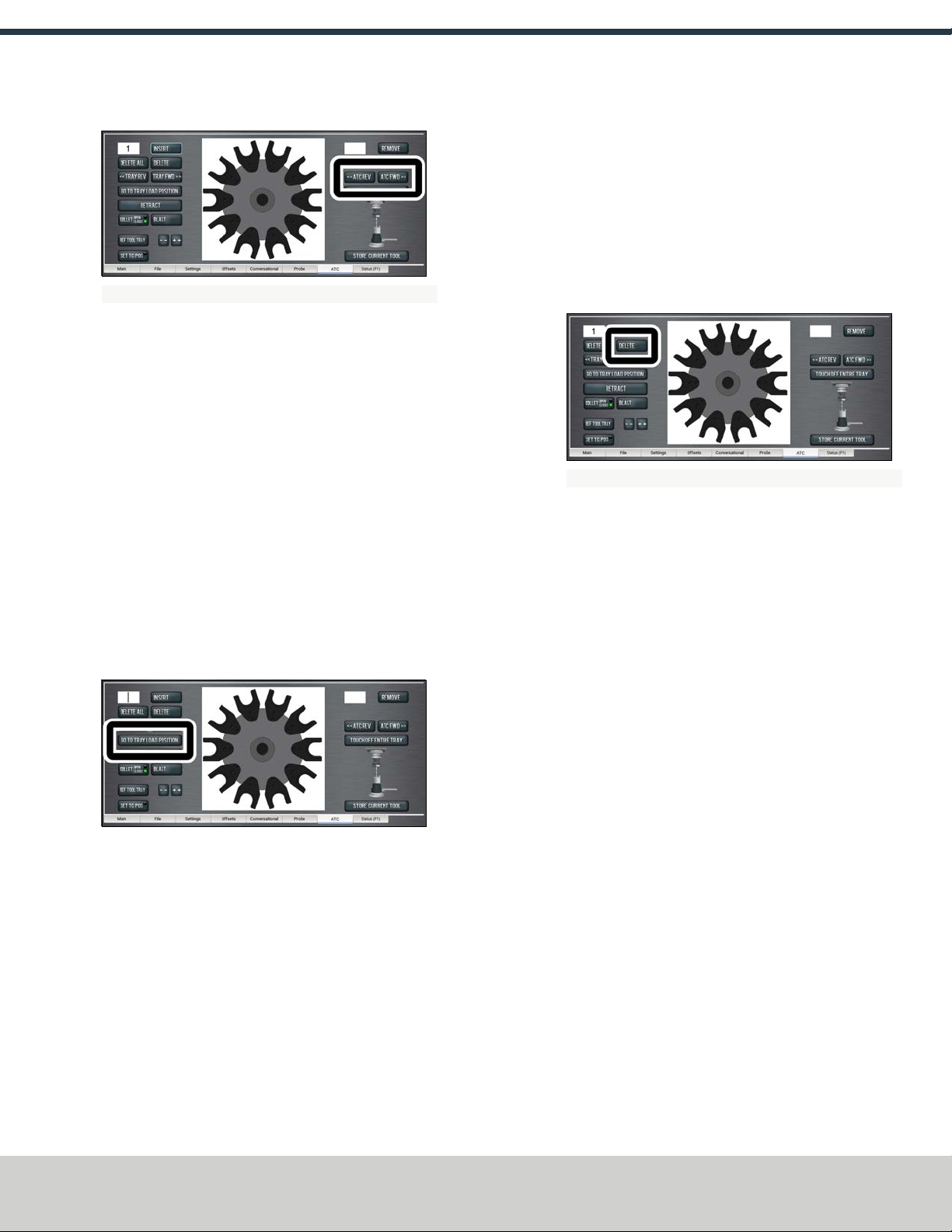
4. From the ATC tab, click ATC FWD or ATC REV.
Figure 3-4: ATCREV and ATCFWD buttons on the ATC tab.
The tray advances to the next location and fetches another
tool.
5. Click Retract.
The tray returns to machining position.
3.1.4 Insert a Tool into the Spindle
Insert a tool into the spindle as follows:
1. Push and hold the button on the ATC.
The collet opens.
2. Insert a tool into the spindle.
3. Release the button.
The collet closes.
3.1.5 Manually Load a Tool into the Tool Tray
1. From the PathPilot® interface, on the ATC tab, click Go To
Tray Load Position.
The spindle head moves up and the ATC moves into the door
open position.
2. Insert a tool into an open fork on the tray.
3. From the ATC tab, type the tool number into the Insert DRO
field, and then press ENTER on the keyboard.
4. Click Insert.
The tool is assigned to the exposed tray slot.
5. Click Tray FWD or Tray REV.
The tray advances to the next slot location.
6. Click Retract.
The tray returns to machining position.
3.1.6 Manually Unload a Tool From the Tool Tray
1. From the PathPilot® interface, on the ATC tab, type the tool
number into the Insert DRO field, and then press ENTER on
the keyboard.
2. Click Go To Tray Load Position.
The spindle head moves up and the ATC moves into the door
open position.
3. Click Delete.
Figure 3-5: Delete button on the ATCtab.
The tool is unassigned from the tray and the tray moves to
that tool.
4. Click Tray FWD or Tray REV.
The tray advances to the next slot location.
5. Click Retract.
The tray returns to machining position.
3.1.7 Retrieve a Tool From the Tool Tray
Depending on your workflow, do one of the following:
lType Txx M6 in the MDI Line field, with xx as the tool
number.
lType the tool number in the Tool DRO field, and then press
ENTER on the keyboard.
3.1.8 Set the Tool Change Height
1. From the PathPilot® interface, slowly jog the Z-axis down (-
Z) over the tool. Stop jogging when the spindle nose just
makes contact with the shoulder of the tool holder.
Page 14
©Tormach® 2018
Specifications subject to change without notice.
tormach.com
TD10427: Owner's Guide: 770M Automatic Tool Changer (0718A)
TECHNICAL DOCUMENT

2. On the ATC tab, click Set TC POS.
Figure 3-6: Set TCPOS button on the ATC tab.
The tool change position is set.
3.1.9 Switch to Manual Tool Changes
From the PathPilot® interface, on the Settings tab, click the
Manual Tool Change radio button.
The Automatic Tool Changer (ATC) is prevented from making
tool changes.
Page 15
©Tormach® 2018
Specifications subject to change without notice.
tormach.com
TD10427: Owner's Guide: 770M Automatic Tool Changer (0718A)
TECHNICAL DOCUMENT

4.1 MAINTAINING THE AUTOMATIC TOOL CHANGER
(ATC)
Read the following sections to understand how to maintain the
ATC:
l"Lubricate the Linear Rails" (below)
l"Replace the Plastic Screws on a Fork" (below)
4.1.1 Lubricate the Linear Rails
The linear rails are self-lubricating. If, after initial installation, you
hear chatter from the linear rails, apply a thin layer of way oil to
the linear rails.
4.1.2 Replace the Plastic Screws on a Fork
The plastic screws that hold the fork to the tool tray are designed
to fail under greater-than-normal loads: when a tool crashes, the
plastic screws snap to prevent damage to the Automatic Tool
Changer (ATC).
If the plastic screws that hold the fork to the tool tray break, do
the following:
1. Remove the broken screws from the fork.
2. Use two included plastic screws to secure the fork to the
tool tray. Make sure the groove on the fork faces the
machine table.
NOTICE! Do not use metal screws to replace broken
screws on an ATC fork. If you do, it could cause
machine damage.
3. Re-adjust the tool tray rotation. Go to "Adjust the Tool Tray
Load Position" (page10).
Page 16
©Tormach® 2018
Specifications subject to change without notice.
tormach.com
TD10427: Owner's Guide: 770M Automatic Tool Changer (0718A)
TECHNICAL DOCUMENT
Other manuals for ATC
2
Table of contents
Other Tormach Industrial Equipment manuals

Tormach
Tormach 51136 User manual

Tormach
Tormach Automatic Tool Changer User manual

Tormach
Tormach 770MX User manual

Tormach
Tormach 24R User manual

Tormach
Tormach 770M User manual

Tormach
Tormach 35550 Technical manual

Tormach
Tormach Slant-PRO 15L User manual

Tormach
Tormach 1100MX User manual

Tormach
Tormach MICROARC 4 User manual

Tormach
Tormach PCNC 770 User manual


